

Datasheet V62C2184096L-85BI, V62C2184096L-85T, V62C2184096L-85B, V62C2184096L-70TI, V62C2184096L-70BI Datasheet (Mosel Vitelic)
...Page 1

MOSEL VITELIC
1
V62C2184096
512K X 8, CMOS STATIC RAM
PRELIMINARY
V62C2184096 Rev. 1.5 June 2000
Features
■
High-speed: 70, 85 ns
■
Ultra low standby current of 4 µ A (max.)
■
Fully static operation
■
All inputs and outputs directly compatible
■
Three state outputs
■
Ultra low data retention current (V
CC
= 1.2V)
■
Operating voltage: 2.3V–3.0V
■
Packages
– 32-Pin TSOP (Standard)
– 36-Ball CSP BGA (8mm x 10mm)
Description
The V62C2184096 is a very low power CMOS
static RAM organized as 524,288 words by 8 bits.
Easy memory expansion is provided by an active
LOW CE1
, and active HIGH CE2, an active LOW
OE, and three static I/O’s. This device has an
automatic power-down mode feature when
deselected.
Device Usage Chart
Operating
Temperature
Range
Package Outline Access Time (ns) Power
Temperature
MarkT B 70 85 L LL
0 °
C to 70 ° C • • • • • • Blank
–40 ° C to +85 ° C•••• • I
Functional Block Diagram
Row Decoder
Sense Amp
1024
x
4096
Column Decoder
Input Buffer
Control
Circuit
A
0
A
1
A
2
A
3
A
4
A
5
A
6
A
7
A
8
A
9
A10A11A12A13A14A15A
16
I/O1
I/O
8
OE
WE
CE1
CE2
A17A
18
Page 2
2
V62C2184096 Rev. 1.5 June 2000
MOSEL VITELIC
V62C2184096
Pin Descriptions
A
0
–A
18
Address Inputs
These 19 address inputs select one of the 512K x 8
bit segments in the RAM.
CE
1
, CE
2
* Chip Enable Inputs
CE
1
is active LOW and CE
2
is active HIGH. Both
chip enables must be active to read from or write to
the device. If either chip enable is not active, the
device is deselected and is in a standby power
mode. The I/O pins will be in the high-impedance
state when deselected.
OE
Output Enable Input
The Output Enable input is active LOW. With chip
enabled, when OE is LOW and WE HIGH, data of
the selected memory location will be available on
the I/O pins. When OE is HIGH, the I/O pins will be
in the high impedance state.
WE
Write Enable Input
The write enable input is active LOW and controls
read and write operations. With the chip enabled,
when WE is HIGH and OE is LOW, output data will
be present at the I/O pins; when WE is LOW and
OE is HIGH, the data present on the I/O pins will be
written into the selected memory locations.
I/O
1
–I/O
8
Data Input and Data Output Ports
These 8 bidirectional ports are used to read data
from and write data into the RAM.
V
CC
Power Supply
GND Ground
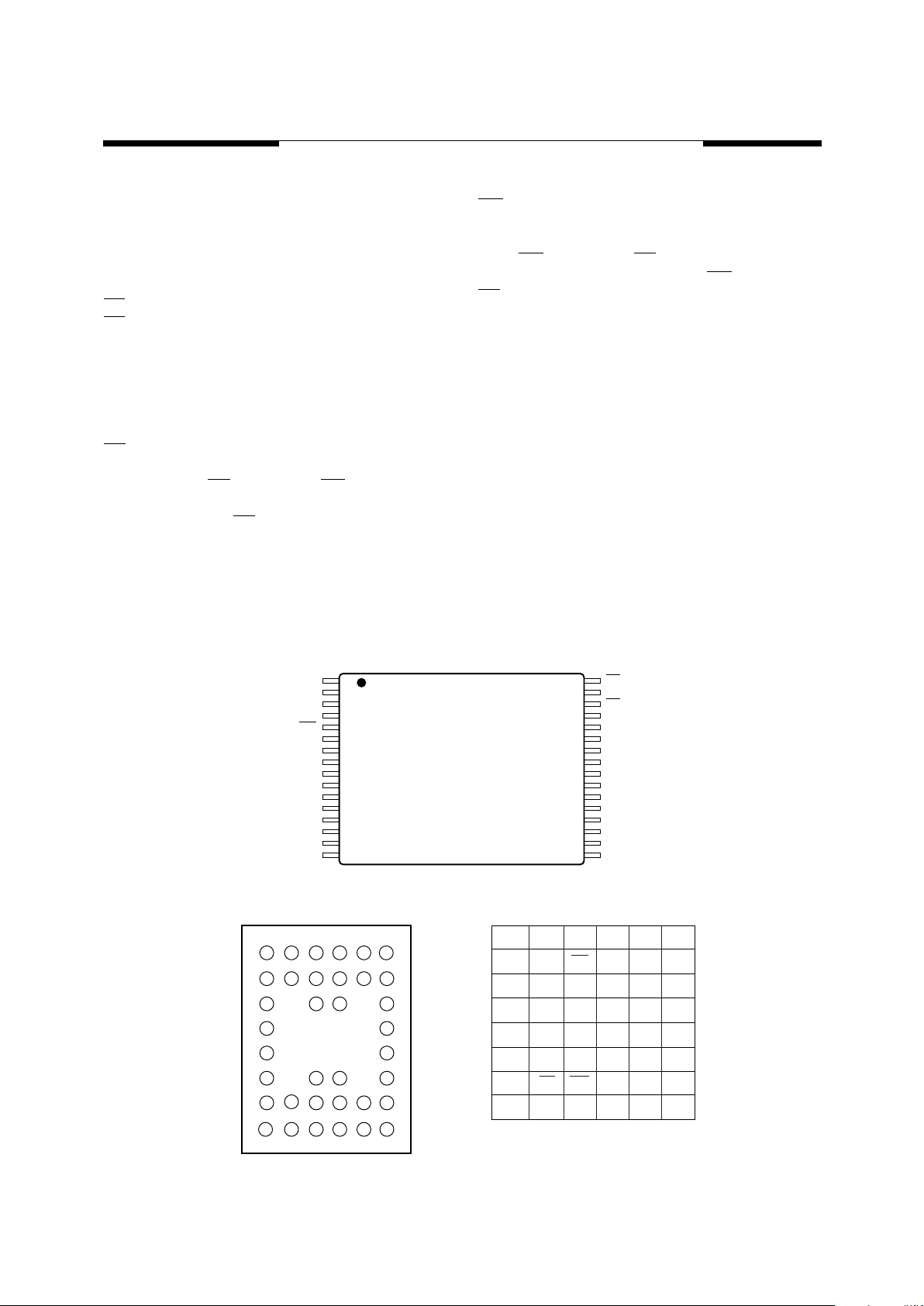
Pin Configurations (Top View)
32-Pin TSOP (Standard)
36 BGA
A11
A9
A8
A13
WE
A18
A15
VCC
A17
A16
A14
A12
A7
A6
A5
A4
OE
A10
CE1
I/O8
I/O7
I/O6
I/O5
I/O4
GND
I/O3
I/O2
I/O1
A0
A1
A2
A3
1
2
3
4
5
6
7
8
9
10
11
12
13
14
15
16
32
31
30
29
28
27
26
25
24
23
22
21
20
19
18
17
A
123456 1
Note: NC means no connect.
NB means no ball.
2
TOP VIEW
TOP VIEW
3456
B
C
D
E
F
G
H
A
A0
I/O5
I/O6
B
C
D
E
F
G
H
VSS
VCC
I/O7
I/O8
A9
A1
A2
NB
NB
NB
NB
OE
A10
CE2
WE
NC
NB
NB
A18
CE1
A11
A3
A4
A5
NB
NB
A17
A16
A12
A6
A7
NB
NB
NB
NB
A15
A13
A8
I/O1
I/O2
VCC
VSS
I/O3
I/O4
A14
*CE
2
is available on BGA package only.
Page 3
MOSEL VITELIC
V62C2184096
3
V62C2184096 Rev. 1.5 June 2000
Part Number Information
Absolute Maximum Ratings
(1)
NOTE:
1. Stresses greater than those listed under “Absolute Maximum Ratings” may cause permanent damage to the device. This is a stress
rating only and functional operation of the device at these or any other conditions above those indicated in the operational sections
of this specification is not implied. Exposure to absolute maximum rating conditions for extended periods may affect reliability.
Capacitance*
Symbol Parameter Commercial Industrial Units
V
CC
Supply Voltage -0.5 to + V
CC
+ 0.5 -0.5 to + V
CC
+ 0.5 V
V
N
Input Voltage -0.5 to + V
CC
+ 0.5 -0.5 to + V
CC
+ 0.5 V
V
DQ
Input/Output Voltage Applied V
CC
+ 0.3 V
CC
+ 0.3 V
T
BIAS
Temperature Under Bias -10 to +125 -65 to +135
°
C
T
STG
Storage Temperature -55 to +125 -65 to +150
°
C
SRAM
FAMILY
C = CMOS PROCESS
62 = STANDARD
21 = 2.3V–3.0V
OPERATING
VOLTAGE
4096K
ORGANIZATION
PKG
SPEED
62 C 821 4096 –
MOSEL-VITELIC
MANUFACTURED
V
8 = 8-bit
70 ns
85 ns
TEMP.
BLANK = 0°C to 70°C
I = -40°C to +85°C
L = LOW POWER
LL = LOW LOW POWER
T = TSOP STANDARD
B = BGA
DENSITY
PWR.
T
A
= 25 ° C, f = 1.0MHz
NOTE:
1. This parameter is guaranteed and not tested.
Truth Table
NOTE:
X = Don’t Care, L = LOW, H = HIGH
Symbol Parameter Conditions Max. Unit
C
IN
Input Capacitance V
IN
= 0V 6 pF
C
OUT
Output Capacitance V
I/O
= 0V 8 pF
Mode CE
1
CE
2
OE
WE
I/O
Operation
Standby H X X X High Z
Standby X L X X High Z
Output Disable L H H H High Z
Read LHLH D
OUT
Write L H X L D
IN
Page 4

4
V62C2184096 Rev. 1.5 June 2000
MOSEL VITELIC
V62C2184096
DC Electrical Characteristics
(over all temperature ranges, V
CC
= 2.3V–3.0V)
NOTES:
1. These are absolute values with respect to device ground and all overshoots due to system or tester noise are included.
2. V
IL
(Min.) = -3.0V for pulse width < t
RC
/2.
3. Maximum value.
Symbol Parameter Test Conditions Min. Typ. Max. Units
V
IL
Input LOW Voltage
(1,2)
-0.5 — 0.4 V
V
IH
Input HIGH Voltage
(1)
2.0 — V
CC
+0.3 V
I
IL
Input Leakage Current V
CC
= Max, V
IN
= 0V to V
CC
—— 1
µ
A
I
OL
Output Leakage Current V
CC
= Max, CE
1
= V
IH
, V
OUT
= 0V to V
CC
—— 1
µ
A
V
OL
Output LOW Voltage V
CC
= Min, I
OL
= 2mA — — 0.4 V
V
OH
Output HIGH Voltage V
CC
= Min, I
OH
= -0.5mA V
CC
–0.4 — — V
Symbol Parameter Comm.
(3)
Ind.
(3)
Units
I
CC1
Average Operating Current, CE
1
= V
IL
, CE
2
= V
CC
– 0.2, Output Open,
V
CC
= Max.
f = fmax 35 40 mA
f = 1 MHz 4 5
I
SB
TTL Standby Current
CE
1
≥
V
IH
, CE
2
≤
V
IL
, V
CC
= Max., f = 0
L 0.5 1 mA
LL 0.3 1
I
SB1
CMOS Standby Current, CE
1
≥
V
CC
– 0.2V, CE2 ≤ 0.2V,
VIN ≥ VCC – 0.2V or VIN ≤ 0.2V, VCC = Max., f = 0
L1015µA
LL 5 7
AC Test Conditions AC Test Loads and Waveforms
Input Pulse Levels 0 to 2.0V
Input Rise and Fall Times 5 ns
Timing Reference Levels 1.1V
Output Load see below
* Includes scope and jig capacitance
C
L
= 30pF + 1TTL Load
C
L
*
TTL
Page 5

MOSEL VITELIC
V62C2184096
5
V62C2184096 Rev. 1.5 June 2000
Data Retention Characteristics
NOTES:
1. tRC = Read Cycle Time
2. TA = +25°C.
Low VCC Data Retention Waveform (1) (CE1 Controlled)
Key to Switching Waveforms
Symbol Parameter Power Min. Typ.
(2)
Max. Units
V
DR
VCC for Data Retention
CE1 ≥ V
CC
– 0.2V, CE2 < 0.2V, VIN ≥ V
CC
– 0.2V,
or VIN ≤ 0.2V
1.2 — 3.0 V
I
CCDR
Data Retention Current
CE1 ≥ VDR – 0.2V, CE2 < 0.2V, VIN ≥ V
CC
– 0.2V,
or VIN ≤ 0.2V, VDR = 1.2V
Com’l L — 1 3 µA
LL — 0.5 2
Ind. L — — 5
LL — — 4
t
CDR
Chip Deselect to Data Retention Time 0 — — ns
t
R
Operation Recovery Time (see Retention Waveform) t
RC
(1)
——ns
V
CC
Data Retention Mode
CE
1
≥ VCC – 0.2V
CE
1
2.0V 2.0V
2.3V
t
CDR
t
R
VDR ≥ 1.2V
2.3V
WAVEFORM INPUTS OUTPUTS
MUST BE
STEADY
WILL BE
STEADY
MAY CHANGE
FROM H TO L
WILL BE
CHANGING
FROM H TO L
MAY CHANGE
FROM L TO H
WILL BE
CHANGING
FROM L TO H
DON'T CARE:
ANY CHANGE
PERMITTED
CHANGING:
STATE
UNKNOWN
DOES NOT
APPLY
CENTER
LINE IS HIGH
IMPEDANCE
“OFF” STATE
Page 6

6
V62C2184096 Rev. 1.5 June 2000
MOSEL VITELIC
V62C2184096
AC Electrical Characteristics
(over all temperature ranges)
Read Cycle
Write Cycle
Parameter
Name Parameter
70 85
UnitMin. Max. Min. Max.
t
RC
Read Cycle Time 70 — 85 — ns
t
AA
Address Access Time — 70 — 85 ns
t
ACS1
Chip Enable Access Time — 70 — 85 ns
t
ACS2
Chip Enable Access Time — 70 — 85 ns
t
OE
Output Enable to Output Valid — 40 — 85 ns
t
CLZ1
Chip Enable to Output in Low Z 10 — 10 — ns
t
CLZ2
Chip Enable to Output in Low Z 10 — 10 — ns
t
OLZ
Output Enable to Output in Low Z 5 — 10 — ns
t
CHZ
Chip Disable to Output in High Z — 30 — 30 ns
t
OHZ
Output Disable to Output in High Z — 25 — 30 ns
t
OH
Output Hold from Address Change 10 — 10 — ns
Parameter
Name Parameter
70 85
UnitMin. Max. Min. Max.
t
WC
Write Cycle Time 70 — 85 — ns
t
CW
Chip Enable to End of Write 60 — 70 — ns
t
AS
Address Setup Time 0—0—ns
tAWAddress Valid to End of Write 60 — 70 — ns
t
WP
Write Pulse Width 50 — 60 — ns
t
WR
Write Recovery Time 0—0—ns
t
WHZ
Write to Output High-Z — 20 — 25 ns
t
DW
Data Setup to End of Write 35 — 40 — ns
t
DH
Data Hold from End of Write 0—0—ns
Page 7

MOSEL VITELIC
V62C2184096
7
V62C2184096 Rev. 1.5 June 2000
Switching Waveforms (Read Cycle)
Read Cycle 1
(1, 2, 6)
Read Cycle 2
(1, 2, 4, 6)
Read Cycle 3
(1, 3, 4, 6)
NOTES:
1. WE
= VIH.
2. CE1 = VIL and CE2 = VIH.
3. Address valid prior to or coincident with CE1 transition LOW and/or CE2 transition HIGH.
4. OE = VIL.
5. Transition is measured ±500mV from steady state with CL = 5pF. This parameter is guaranteed and not 100% tested.
6. CE2 is offered on BGA package only.
ADDRESS
OE
I/O
t
RC
t
AA
t
OE
t
OLZ
t
OH
t
OHZ
(5)
ADDRESS
I/O
t
RC
t
AA
t
OH
t
OH
I/O
ADDRESS
CE
1
CE
2
t
ACS1
t
ACS2
t
CLZ1
(5)
t
CLZ2
(5)
t
CHZ
(5)
Page 8

8
V62C2184096 Rev. 1.5 June 2000
MOSEL VITELIC
V62C2184096
Switching Waveforms (Write Cycle)
Write Cycle 1 (WE Controlled)
(4, 7)
Write Cycle 2 (CE Controlled)
(4, 7)
NOTES:
1. The internal write time of the memory is defined by the overlap of CE
1
and CE2 active and WE low. All signals must be active to
initiate and any one signal can terminate a write by going inactive. The data input setup and hold timing should be referenced to
the second transition edge of the signal that terminates the write.
2. tWR is measured from the earlier of CE1 or WE going high, or CE2 going LOW at the end of the write cycle.
3. During this period, I/O pins are in the output state so that the input signals of opposite phase to the outputs must not be applied.
4. OE = VIL or VIH. However it is recommended to keep OE at VIH during write cycle to avoid bus contention.
5. If CE1 is LOW and CE2 is HIGH during this period, I/O pins are in the output state. Then the data input signals of opposite phase
to the outputs must not be applied to them.
6. tCW is measured from CE1 going low or CE2 going HIGH to the end of write.
7. CE2 is offered on BGA package only.
ADDRESS
OUTPUT
INPUT
CE
1
CE
2
WE
t
WC
t
CW
(6)
t
CW
(6)
t
DW
t
DH
t
AW
t
WR
(2)
t
WHZ
t
WP
(1)
t
AS
ADDRESS
OUTPUT
High-Z
INPUT
CE
1
CE
2
WE
t
WC
t
DW
t
DH
t
AW
t
CW
(6)
t
CW
(6)
t
WR
(2)
t
AS
(4)
(5)
Page 9

MOSEL VITELIC
V62C2184096
9
V62C2184096 Rev. 1.5 June 2000
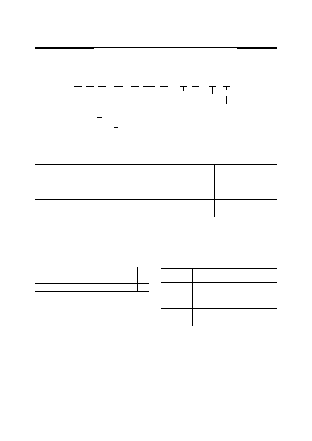
Package Diagrams
32-Pin TSOP (Standard)
36 Ball—8x10 BGA
0.032 [0.813] TYP.
0.020 [0.508] SBC
0.003 [0.076] MAX.
0.020 [0.508] MAX.
0.024 ± 0.004
[0.610 ± 0.102]
SEATING
PLANE
0.010 [.254]
See Detail “A”
Detail “A”
0.724 TYP. (0.728 MAX.)
[18.39 TYP. (18.49 MAX)]
0.787 ± 0.008
[19.99 ± 0.203]
0.009 ± 0.002
[0.229 ± 0.051]
0.315 TYP.
(0.319 MAX.)
8.00 TYP.
(8.10 MAX.)
0.035 ± 0.002
[0.889 ± 0.051]
0.047 [1.19] MAX.
0.005 MIN.
0.007 MAX.
0.127 MIN.
0.178 MAX.
Units in inches [mm]
E1
E
6
5
4
D
ABCDE
BOTTOM VIEW
SIDE VIEW
aaa
FGH
D1
b
SOLDER BALL
3
2
1
e
A
C
A1
SYMBOL
A
A1
b
c
D
D1
E
E1
e
aaa
UNIT.MM
1.05+0.15
0.25±0.05
0.35±.0.05
0.30(TYP)
10.00±0.10
5.25
8.00±0.10
3.75
0.75TYP
0.10
Page 10

MOSEL VITELIC
WORLDWIDE OFFICES V62C2184096
MOSEL VITELIC 3910 N. First Street, San Jose, CA 95134-1501 Ph: (408) 433-6000 Fax: (408) 433-0952 Tlx: 371-9461
© Copyright 2000, MOSEL VITELIC Inc.
6/00
Printed in U.S.A.
The information in this document is subject to change without
notice.
MOSEL VITELIC makes no commitment to update or keep current the information contained in this document. No part of this
document may be copied or reproduced in any form or by any
means without the prior written consent of MOSEL-VITELIC.
MOSEL VITELIC subjects its products to normal quality control
sampling techniques which are intended to provide an assurance
of high quality products suitable for usual commercial applications. MOSEL VITELIC does not do testing appropriate to provide
100% product quality assurance and does not assume any liability for consequential or incidental arising from any use of its products. If such products are to be used in applications in which
personal injury might occur from failure, purchaser must do its
own quality assurance testing appropriate to such applications.
U.S. SALES OFFICES
U.S.A.
3910 NORTH FIRST STREET
SAN JOSE, CA 95134
PHONE: 408-433-6000
FAX: 408-433-0952
HONG KONG
19 DAI FU STREET
TAIPO INDUSTRIAL ESTATE
TAIPO, NT, HONG KONG
PHONE: 852-2666-3307
FAX: 852-2770-8011
TAIWAN
7F, NO. 102
MIN-CHUAN E. ROAD, SEC. 3
TAIPEI
PHONE: 886-2-2545-1213
FAX: 886-2-2545-1209
NO 19 LI HSIN RD.
SCIENCE BASED IND. PARK
HSIN CHU, TAIWAN, R.O.C.
PHONE: 886-3-579-5888
FAX: 886-3-566-5888
SINGAPORE
10 ANSON ROAD #23-13
INTERNATIONAL PLAZA
SINGAPORE 079903
PHONE: 65-3231801
FAX: 65-3237013
JAPAN
WBG MARIVE WEST 25F
6, NAKASE 2-CHOME
MIHAMA-KU, CHIBA-SHI
CHIBA 261-7125
PHONE: 81-43-299-6000
FAX: 81-43-299-6555
UK & IRELAND
SUITE 50, GROVEWOOD
BUSINESS CENTRE
STRATHCLYDE BUSINESS
PARK
BELLSHILL, LANARKSHIRE,
SCOTLAND, ML4 3NQ
PHONE: 01698-748515
FAX: 01698-748516
GERMANY
(CONTINENTAL
EUROPE & ISRAEL)
71083 HERRENBERG
BENZSTR. 32
GERMANY
PHONE: +49 7032 2796-0
FAX: +49 7032 2796 22
NORTHWESTERN
3910 NORTH FIRST STREET
SAN JOSE, CA 95134
PHONE: 408-433-6000
FAX: 408-433-0952
SOUTHWESTERN
302 N. EL CAMINO REAL #200
SAN CLEMENTE, CA 92672
PHONE: 949-361-7873
FAX: 949-361-7807
CENTRAL,
NORTHEASTERN &
SOUTHEASTERN
604 FIELDWOOD CIRCLE
RICHARDSON, TX 75081
PHONE: 972-690-1402
FAX: 972-690-0341
 Loading...