

Page 1
UTV200
20 Watts, 26.5 Volts, Class A
UHF Television - Band IV & V
GENERAL DESCRIPTION
The UTV 200 is a COMMON EMITTER transistor capable of providing 20
Watt Peak, Class A, RF Output Power over the band 470 - 860 MHz. The
transistor includes double input prematching for full broadband capability.
Gold Metalization and Diffused Ballasting are used to provide high reliability
and supreme ruggedness.
ABSOLUTE MAXIMUM RATINGS
Maximum Power Dissipation @ 25 C 80 Watts
Maximum Voltage and Current
BVces Collector to Emitter Voltage 50 Volts
BVceo Collector to Emitter Voltage 28 Volts
BVebo Emitter to Base Voltage 4.0 Volts
Ic Collector Current 4.5 Amps
Ma ximum Temperatures
Storage Temperature - 65 to + 200 C
Operating Junction Temperature + 200 C
ELECTRICAL CHARACTERISTICS @ 25 C
o
o
o
O
CASE OUTLINE
55JV, STYLE 2
SYMBOL CHARACTERISTICS TEST CONDITIONS MIN TYP MAX UNITS
Pout
Pin
Pg
1
IMD
VSWR
Power Out - Pk Sync
Power Input
Power Gain
Intermodulation Distortion
1
Load Mismatch Tolerance
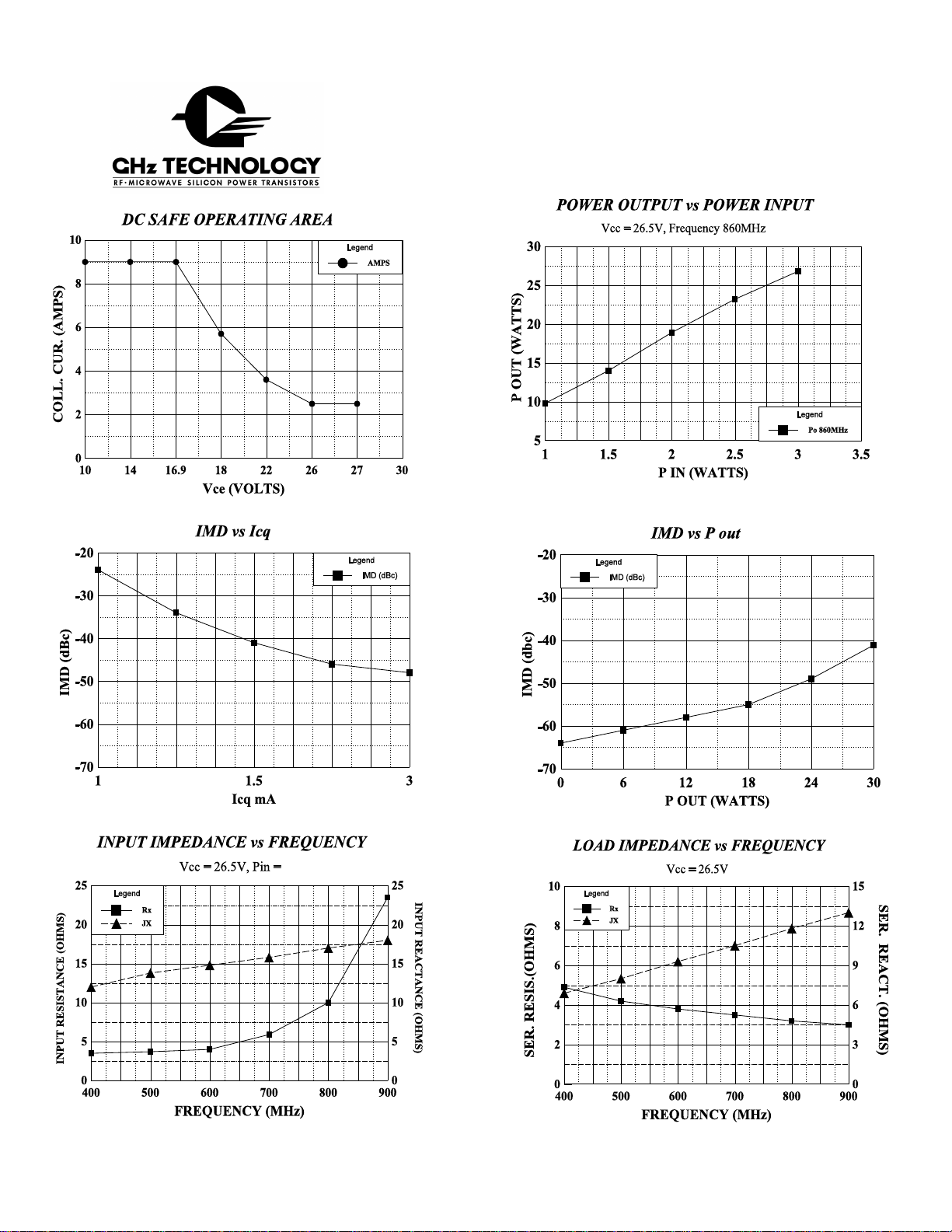
F = 470 - 860 MHz
Vcc = 26.5 Volts
Ic = 2.7 Amps
Pref = 20Watts
F = 860 MHz
20
8.5 9.5
-48
2.8
Watts
Watts
-46
3:1
dB
dB
2
LVceo
BVces
BVebo
2
h
FE
2
Cob
θ
jc
Collector to Emitter Breakdown
2
Collector to Base Breakdown
2
Emitter to Base Breakdown
Current Gain
Output Capacitance
Thermal Resistance
Ic = 40 mA
Ic = 20mA
Ie = 10 mA
Vce = 5 V, 1 A
Vcb = 26 V, F = 1 MHz
Tc = 25 C
o
28
50
4
10 150
36
1.2
Volts
Volts
Volts
pF
o
C/W
Note 1: F1=860 MHz, F2=863.5 MHz, F3=864.5 Mhz
European test method, Vision = - 8dB, Sideband= - 16dB, Sound = -7 dB
Note 2: Per side
Initial Issue June, 1994
GHz TECHNOLOGY INC. RESERVES THE RIGHT TO MAKE CHANGES WITHOUT FURTHER NOTICE. GHz RECOMMENDS THAT
BEFORE THE PRODUCT(S) DESCRIBED HEREIN ARE WRITTEN INTO SPECIFICATIONS, OR USED IN CRITICAL APPLICATIONS,
THAT THE PERFORMANCE CHARACTERISTICS BE VERIFIED BY CONTACTING THE FACTORY.
GHz Technology Inc. 3000 Oakmead Village Drive, Santa Clara, CA 95051-0808 Tel. 408 / 986-8031 Fax 408 / 986-8120
Page 2
UTV200
Page 3

UTV-200
Vbe 2
C5
C24
+
+
C16
C8
L1
C2
T1
C4
L5
L2
C7
++
C25 C26
50 OHM
RF IN
C1
T2
C3
CAPACITORS
C1,C6=4.7 pF ATC series A
Vbe 1
C2,C3,C20,C21=33 pF ATC series A
C4,C9=1.2-3.5 pF film diel. trimmer
C5,C7,C11,C12=0.01 mF, 50V Tantalum
C8,C15,C17,C25=1 mF, 50 V Tantalum
C10,C16,C27,C12=0.1 mF 50 V disc ceramic
C13=0.6-6 pF piston trimmer
C19=0.35-3.5 pF piston trimmer
C18,C24,C14,C26=10 mF, 50 V
C28,C30=0.001 mF, 50 V disc ceramic
INDUCTORS
L1,L2=0.46 microHenry molded
L3,L4=1 turn #18 magnet wire on a 0.325" form
C31=100 mF, 50 V electrolytic
RESISTORS
R1=10 Ohm, 1/2 W Carbon
R2,R6=500 Ohm potentiometer
R3,R7=4.7K Ohm, 3W, 1% Carbon
R4,R8=1 Ohm, 3W, 1% Carbon film
R5,R9=47 Ohm, 1/4W Carbon film
August 1996
TRANSFORMERS
T1,T2,T3,T4=50 Ohm semi-rigid coax cable
(0.056" X 1.1") soldered to 0.035" X 1.1" microstrip
L3
L5
C9
C6
L6
C10
TRANSISTORS
Q1=GHz UTV-200
Q2,Q3=MJE172
Q1
Vce 1
C5
C28
+
C8 C14
+
C15
L3
L7
C19
C13
L8
L4
C12
+
C30
C29
Vce 2
MICROSTRIPLINES
L3,L4=0.075" X 0.65"
L5,L6=0.120" X 0.31"
L7,L8=0.120" X 1.33"
C18
CR1
R2
C20
C21
+
C17
BIAS CIRCUIT
+
R3
R4 R6 R8
C31
Vce 1
Q2
R5
Vbe 1
DIODES
CR1,CR2=IN4148
T3
C22
C23
T4
CR2
R7
R1
50 OHM
RF OUT
Vce 2
Q3
R9
Vbe 2
 Loading...