

Datasheet UT06MRA500, UT06MRA450, UT06MRA600, UT06MRA550, UT06MRA400 Datasheet (Aeroflex UTMC)
...Page 1

Semicustom Products
UT0.6µCRΗ/SRH Commercial RadHardTM and Strategic
RadHard
TM
Gate Array Family
Data Sheet May 2002
FEATURES
q Multiple gate array sizes up to 600,000 usable equivalent
gates
q Toggle rates up to 150 MHz
q Advanced 0.6µ (0.5µL
eff
) radiation-tolerant silicon gate
CMOS processed in a commercial fab
q Operating voltage of 5V and/or 3.3V
q QML Class Q & V compliant
q Designed specifically for high reliability applications
q Commercial RadHardTM for radiation-tolerant to 300K
rads to meet space requirements and SEU-immune to less
than 2.0E-10 errors/bit-day
q Strategic RadHardTM for radiation environments to 1
Mega rads to meet space requirements and SEU-immune
to less than 2.0E-10 errors/bit-day
q JTAG (IEEE 1149.1) boundary-scan supported
q Low noise package technology for high speed circuits
q Design support using Mentor Graphics® and SynopsysTM
in VHDL or Verilog design languages on Sun® and Linux
workstations
q Supports cold sparing fo r power down applications
q Supports voltage translation
- 5V bus to 3.3V bus
- 3.3V bus to 5V bus
PRODUCT DESCRIPTION
The high-performance UT0.6 µCRH/SRH gate array family
features densities up to 600,000 equivalent gates and is available in MIL-PRF-38535 QML Q and V product assurance
levels and is radiation-tolerant.
The Commercial RadHardTM and Strategic RadHardTMsilicon is fabricated at American Microsystems Incorporated
(AMI) using a minimally invasive processing module, developed by UTMC, that enhances the total dose radiation
hardness of the field and gate oxides while maintaining circuit
density and reliability. In addition, for both greater transient
radiation-hardness and latchup immunity, the UTMC 0.6µ
process is built on epitaxial substrate wafers.
Developed using UTMC’s patented architectures, the
UT0.6µCRH/SRH gate array family uses a highly efficient
continuous column transistor architecture for the internal cell
construction. Combined with state-of-the-art placement and
routing tools, the utilization of available transistors is maximized using three levels of metal interconnect.
The UT0.6 µCRH/SRH family of gate arrays is supported by
an extensive cell library that includes SSI, MSI, and 54XX
equivalent functions, as well as configurable RAM and cores.
UTMC’s core library includes the following functions:
• Intel 80C31® equivalent
• Intel 80C196® equivalent
• MIL-STD-1553 functions (BRCTM, RTI, RTMP)
• MIL-STD-1750 microprocessor
• RISC microcontroller
• Configurable RAM (SRAM, DPSRAM)
• USART (8 2C51)
• EDAC
Page 2
2
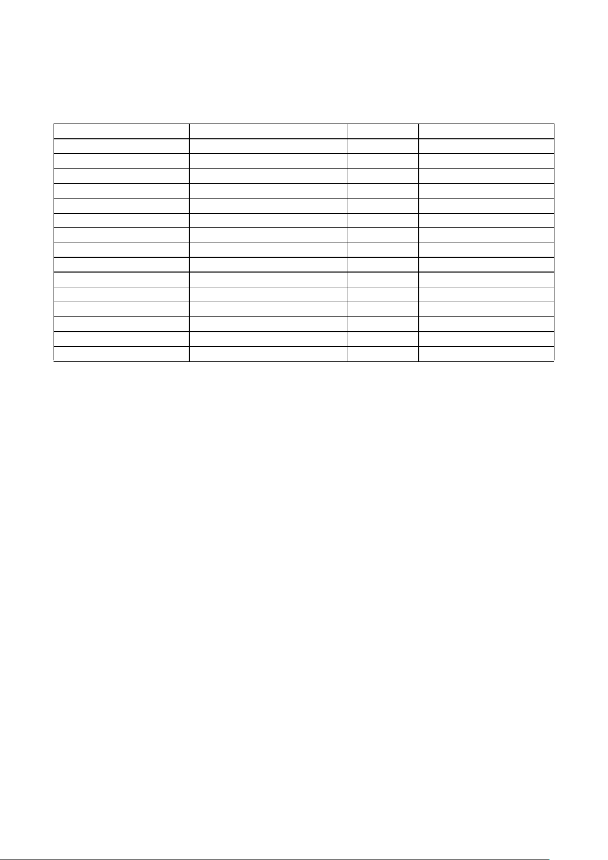
Table 1. Gate Densities
Notes:
1.Based on NAND2 equivalents. Actual usable gate count is design-dependent. Estimates reflect a mix of functions including RAM.
2.Includes five pins that may or may not be reserved for JTAG boundary-scan, depending on user requirements.
3.Reserved for dedicated VDD/VSS and V
DDQ/VSSQ
.
Low-noise Device and Package Solutions
The UT0.6µCRH/SRH array family’s output drivers feature pro-
grammable slew rate control for minimizing noise and switching
transients. This feature allows the user to optimize edge characteristics to match system requirements. Separate on-chip power
and ground buses are provided for internal cells and output drivers which further isolate internal design circuitry from switching
noise.
In addition, Aeroflex UTMC offers advanced low-noise package
technology with multi-layer, co-fired ceramic construction featuring built-in isolated power and ground planes (see Table 2).
These planes provide lower overall resistance/inductance
through power and ground paths which minimize voltage drops
during periods of heavy switching. These isolated planes also
help sustain supply voltage during dose rate events, thus preventing rail span collapse.
Flatpacks are available with up to 352 leads; PGAs are available
with up to 299 pins and LGAs to 472 pins. Aeroflex UTMC’s
flatpacks feature a non-conductive tie bar that helps maintain
lead integrity through test and handling operations. In addition
to the packages listed in Table 2, Aeroflex UTMC offers custom
package development and package tooling modification services
for individual requirements.
DEVICE PART NUMBERS EQUIVALENT USABLE GATES1SIGNAL I/O2POWER & GROUND PADS
3
UT06MRA010 10,000 58 6
UT06MRA025 25,000 192 48
UT06MRA050 50,000 192 48
UT06MRA075 75,000 308 76
UT06MRA100 100,000 308 76
UT06MRA150 150,000 308 76
UT06MRA200 200,000 432 96
UT06MRA250 250,000 432 96
UT06MRA300 300,000 432 96
UT06MRA350 350,000 432 96
UT06MRA400 400,000 544 144
UT06MRA450 450,000 544 144
UT06MRA500 500,000 544 144
UT06MRA550 550,000 544 144
UT06MRA600 600,000 544 144
Page 3
3
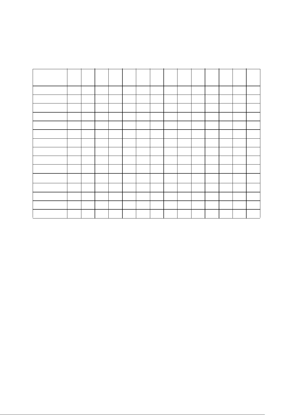
Table 2. Packages
Notes:
1. The number of device I/O pads available may be restricted by the selected package.
2. PGA packages have one additional non-connected index pin (i.e., 84 + 1 index pin = 85 total package pins for the 85 PGA).
Contact Aeroflex UTMC for specific package drawings.
PACKAGE
TYPE/
LEADCOUNT
1
025 050 075 100 150 200 250 300 350 400 450 500 550 600
Flatpack
68 X X X
84 X X
132 X X
172 X X X X X
196 X X X X X
256 X X X X X X X X X
304 X X X X X X X X X
340 X X X X X X X X X
352 X X X X X
PGA
2
281 X X X X
299 X X X X
LGA
472 X X X X
Page 4
4
Extensive Cell Library
The UT0.6µCRH/SRH family of gate arrays is supported by an
extensive cell library that includes SSI, MSI, and 54XX-equivalent functions, as well as RAM and other library functions. Userselectable options for cell configurations include scan for all register elements, as well as output drive strength. Aeroflex
UTMC’s core library includes the following functions:
• Intel® 80C31 equivalent
• Intel® 80C196 equivalent
• MIL-STD-1553 functions (BCRTM, RTI, RTMP)
• MIL-STD-1750 microprocessor
• Standard microprocessor peripheral functions
• Configurable RAM (SRAM, DPsRAM)
• RISC Microcontroller
• USART (82C51)
• EDAC
Refer to Aeroflex UTMC’s UT0.6µCRH/SRH Design Manual
for complete cell listing and details.
I/O Buffers
The UT0.6 µCRH/SRH gate array family offers up to 544 signal
I/O locations (note: device signal I/O availability is affected by
package selection and pinout.) The I/O cells can be configured
by the user to serve as input, output, bidirectional, three-state, or
additional power and ground pads. Output drive options range
from 2 to 12mA. To drive larger off-chip loads, output drivers
may be combined in parallel to provide additional drive up to
24mA.
Other I/O buffer features and options include:
• Slew rate control
• Pull-up and pull-down resistors
• TTL, CMOS, and Schmitt levels
• Cold sparing
• Voltage translation
- 5V bus to 3.3V bus
- 3.3V bus to 5V bus
JTAG Boundary-Scan
The UT0.6 µCRH/SRH arrays provide for a test access port and
boundary-scan that conforms to the IEEE Standard 1149.1
(JTAG). Some of the benefits of this capability are:
• Easy test of complex assembled printed circuit
boards
• Gain access to and control of internal scan paths
• Initiation of Built-In Self Test
Clock Driver Distribution
Aeroflex UTMC design tools provide methods for balanced
clock distribution that maximize drive capability and minimize
relative clock skew between clocked devices.
Speed and Performance
Aeroflex UTMC specializes in high-performance circuits designed to operate in harsh military and radiation environments.
Table 3 presents a sampling of typical cell delays.
Note that the propagation delay for a CMOS device is a function
of its fanout loading, input slew, supply voltage, operating temperature, and processing radiation tolerance. In a radiation
environment, additional performance variances must be considered. The UT0.6µCRH/SRH array family simulation models
account for all of these effects to accurately determine circuit
performance for its particular set of use conditions.
Power Dissipation
Each internal gate or I/O driver has an average power consumption based on its switching frequency and capacitive loading.
Radiation-tolerant processes exhibit power dissipation that is
typical of CMOS processes. For a rigorous power estimating
methodology, refer to the Aeroflex UTMC UT0.6µCRH/SRH
Design Manual or consult with a Aeroflex UTMC Applications
Engineer.
Typical Power Dissipation
1.1µW/Gate-MHz@5.0V 0.4µW/Gate-MHz@3.3V
Page 5
5
Table 3. Typical Cell Delays
Note:
1. All specifications in ns (typical). Output load capacitance is 50pF. Fanout loading for input buffers and gates is the equivalent of two gate input loads.
CELL OUTPUT
TRANSITION
PROPAGATION
DELAY
1
Internal Gates V
DD
= 5.0V V
DD
= 3.3V
INV1, Inverter HL .15 .16
LH .23 .29
INV4, Inverter 4X HL .06 .07
LH .10 .16
NAND2, 2-Input NAND HL .19 .25
LH .22 .33
NOR2, 2-Input NOR HL .16 .22
LH .32 .45
DFF - CLK to Q HL .81 1.12
LH .76 1.06
HL .75 1.05
LH .61 .85
Output Buffers
OC5050N4, CMOS HL 3.85 2.15
LH 4.66 3.76
OT5050N4, TTL, 4mA HL 5.58 5.49
LH 2.52 2.93
OT5050N12, TTL, 12mA HL 2.42
LH 1.29
Input Buffers
IC5050, CMOS HL .81 1.07
LH 1.16 1.18
IT5050, TTL HL 1.39 1.12
LH 1.16 1.30
Page 6

6
ASIC DESIGN SOFTWARE
Using a combination of state-of-the-art third-party and
proprietary design tools, Aeroflex UTMC delivers the CAE
support and capability to handle complex, high-performance
ASIC designs from design concept through design verification
and test.
Aeroflex UTMC’s flexible circuit creation methodology
supports high level design by providing UT0.6 µCRH/SRH
libraries for Mentor Graphics and Synopsys synthesis tools.
Design verification is performed in any VHDL or Verilog
simulator or the Mentor Graphics environment, using Aeroflex
UTMC’s robust libraries. Aeroflex UTMC also supports
Automatic Test Program Generation to improve design testing.
Aeroflex UTMC HDL DESIGN SYSTEMS
Aeroflex UTMC offers a Hardware Description Language
(HDL) design system supporting VHDL and Verilog. Both the
VHDL and Verilog libraries provide sign-off quality models
and robust tools.
The VHDL libraries are VITAL 3.0 compliant, and the Verilog
libraries are OVI 1.0 compliant.With the library capabilities
Aeroflex UTMC provides, you can use High Level Design
methods to synthesize your design for simulation. Aeroflex
UTMC also provides tools to verify that your HDL design will
result in working ASIC devices.
Either of Aeroflex UTMC’s HDL design system lets you easily
access Aeroflex UTMC’s RadHard capabilities.
ADVANTAGES OF THE AEROFLEX UTMC HDL
DESIGN SYSTEMS
• The Aeroflex UTMC HDL Design System gives you the
freedom to use tools from Synopsys, Mentor Graphics,
Cadence, Viewlogic, and other vendors to help you
synthesize and verify a design.
• Aeroflex UTMC’s Logic Rules Checker and Tester Rules
Checker allow you to verify partial or complete designs for
compliance with Aeroflex UTMC design rules.
• Aeroflex UTMC HDL Design System accepts backannotation of timing information through SDF.
• Your design stays entirely within the language in which
you started (VHDL or Verilog) preventing conversion
headaches.
XDTsm (eXternal Design Translation)
Through Aeroflex UTMC’s XDT services, customers can
convert an existing non-Aeroflex UTMC design to Aeroflex
UTMC’s processes. The XDT tool is particularly useful for
converting an FPGA to a Aeroflex UTMC radiation-tolerant
gate array. The XDT translation tools convert industry standard
netlist formats and vendor libraries to Aeroflex UTMC formats
and libraries. Industry standard netlist formats supported by
Aeroflex UTMC include:
• VHDL
• Verilog HDL
TM
• FPGA source files (Actel, Altera, Xilinx)
• EDIF
• Third-party netlists supported by Synopsys
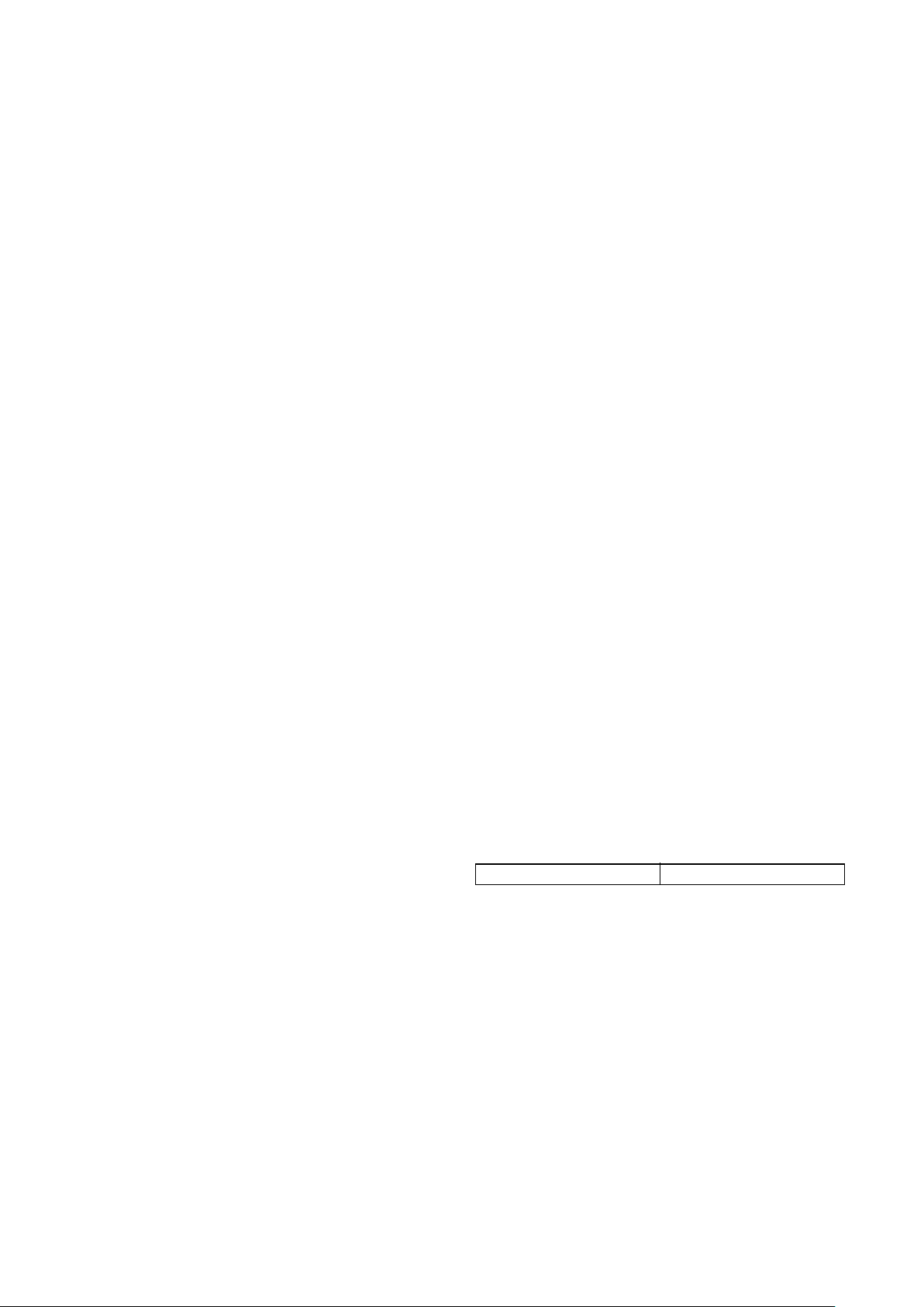
Mentor
ModelSim
HDL Tool
Supplier
Completed
ASIC Design
Cadence
Leapfrog/
Verilog XL
Viewlogic
SpeedWave/
VCS
Synopsys
VSS/VCS
High Level Design Activities
UTMC HDL
Design System
Aeroflex UTMC HDL Design Flow
Page 7

7
AEROFLEX UTMC MENTOR GRAPHICS DESIGN
SYSTEM
The Aeroflex UTMC Mentor Graphics Design System software
is fully integrated into the Mentor Graphics design
environment, making it familiar and easy to use. Aeroflex
UTMC tools support Mentor functions such as crosshighlighting, graphical menus, and design navigation.
After creating a design in the Mentor Graphics environment,
you can easily verify the design for electrical rules compliance
with the Aeroflex UTMC Logic Rules Checker. Testability can
be verified with the Aeroflex UTMC Tester Rules Checker.
Both of these tools are fully integrated into the Mentor
Graphics Environment.
When you have completed all design activities, Aeroflex
UTMC’s Design Transfer tool captures all the required files
and prepares them for easy transfer to Aeroflex UTMC.
Aeroflex UTMC uses this data to convert your design into a
packaged and tested device.
ADVANTAGES OF THE AEROFLEX UTMC MENTOR
DESIGN SYSTEM
• Aeroflex UTMC customers have successfully used the
Aeroflex UTMC Mentor Graphics Design System for over
a decade.
• Aeroflex UTMC’s Logic and Tester Rules Checker tools
allow you to verify partial or complete designs for
compliance with Aeroflex UTMC manufacturing practices
and procedures.
• The Design System accepts pre-and post-layout timing
information to ensure your design results in devices that
meet your specifications.
• The Design System supports Leonardo, and database
transfer between Synopsys and Mentor.
• The Design System supports powerful Mentor Graphics
ATPG capabilities .
TOOLS SUPPORTED BY AEROFLEX UTMC
Aeroflex UTMC supports libraries for:
• Mentor Graphics
• ModelSim
• Synopsys
• Design Compiler
• PrimeTime
• Formality
• TetraMax
• VITAL-compliant VHDL Tools
• OVI-compliant Verilog Tools
TRAINING AND SUPPORT
Aeroflex UTMC personnel conduct training classes tailored to
meet individual needs. These classes can address a wide mix of
engineering backgrounds and specific customer concerns.
Applications assistance is also available through all phases of
ASIC Design.
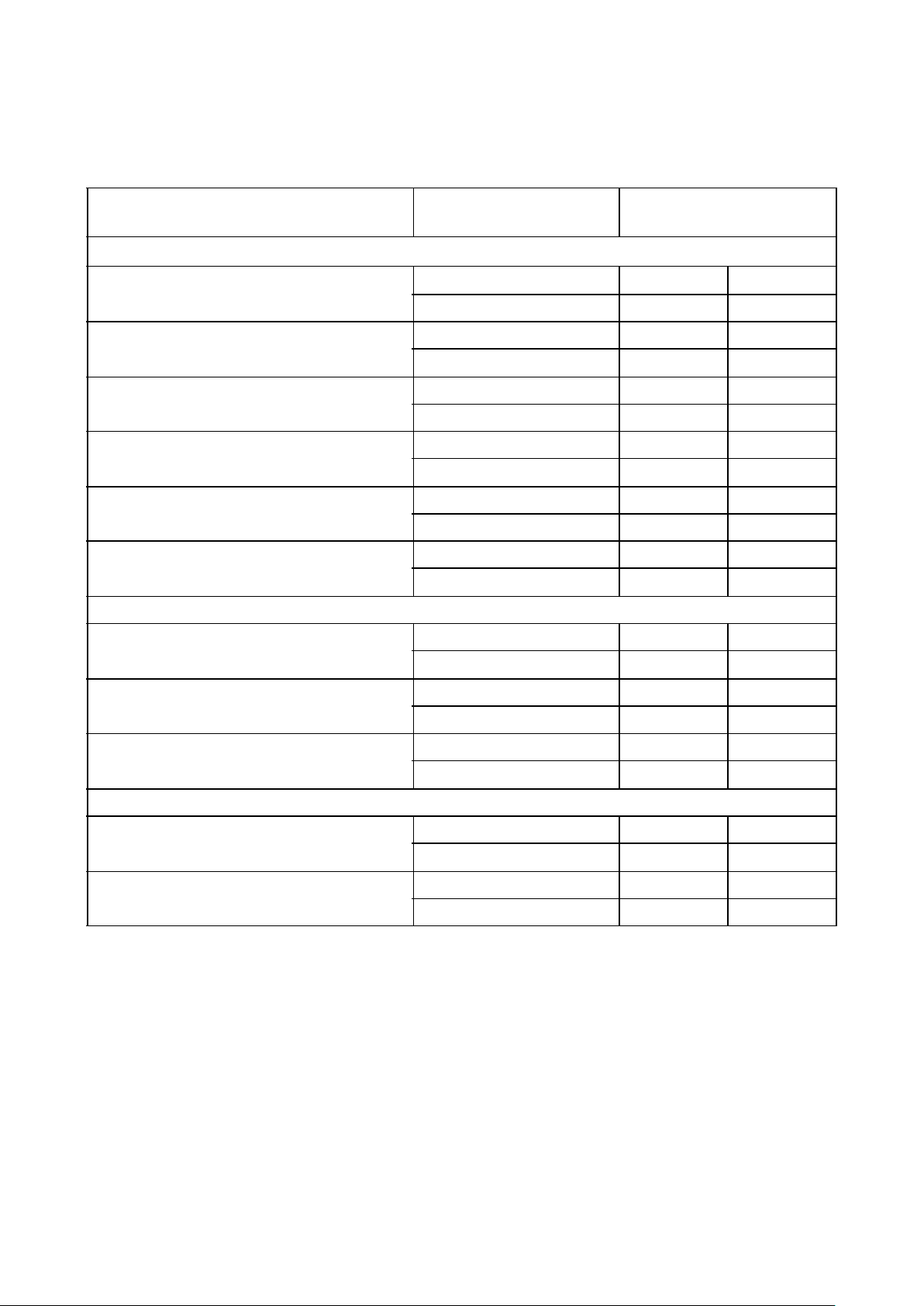
Design
Manufacturing
UTMC Mentor
Design System
Translate an
External
Design
Convert an
FPGA
Schematic
Entry
Synthesis
Design Idea
Aeroflex UTMC Mentor Graphics Design
Page 8

8
PHYSICAL DESIGN
Using three layers of metal interconnect, Aeroflex UTMC
achieves optimized layouts that maximize speed of critical nets,
overall chip performance, and design density up to 600,000
equivalent gates.
Test Capability
Aeroflex UTMC supports all phases of test development from
test stimulus generation through high-speed production test. This
support includes ATPG, fault simulation, and fault grading. Scan
design options are available on all UT0.6µCRH/SRH storage
elements. Automatic test program development capabilities handle large vector sets for use with Aeroflex UTMC’s LTX/
Trillium MicroMasters, supporting high-speed testing (up to
80MHz with pin multiplexing).
Unparalleled Quality and Reliability
Aeroflex UTMC is dedicated to meeting the stringent performance requirements of aerospace and defense systems suppliers.
Aeroflex UTMC maintains the highest level of quality and reliability through our Quality Management Program under MILPRF-38535 and ISO-9001. In 1988, we were the first gate array
manufacturer to achieve QPL certification and qualification of
our technology families. Our product assurance program has kept
pace with the demands of certification and qualification.
Our quality management plan includes the following activities
and initiatives.
• Quality improvement plan
• Failure analysis program
• SPC plan
• Corrective action plan
• Change control program
• Standard Evaluation Circuit (SEC) and Technology Charac-
terization Vehicle (TCV) assessment program
• Certification and qualification program
Because of numerous product variations permitted with customer
specific designs, much of the reliability testing is performed using a Standard Evaluation Circuit (SEC) and Technology
Characterization Vehicle (TCV). The TCV utilizes test structures
to evaluate hot carrier aging, electromigration, and time dependent test samples for reliability testing. Data from the wafer-level
testing can provide rapid feedback to the fabrication process, as
well as establish the reliability performance of the product before
it is packaged and shipped.
Radiation Tolerance
Aeroflex UTMC incorporates radiation-tolerance techniques in
process design, design rules, array design, power distribution,
and library element design. All key radiation-tolerance process
parameters are controlled and monitored using statistical methods and in-line testing.
Notes:
1. Total dose Co-60 testing is in accordance with MIL-STD-883,
Method 1019. Data sheet electrical characteristics guaranteed to 1.0E5
rads(Si O2). All post-radiation values measured at 25°C.
2. Total dose Co-60 testing is in accordance with MIL-STD-883,
Method 1019 at dose rates <1 rad(SiO2)/s.
3. Short pulse 20ns FWHM (full width, half maximum).
4. Is design dependent; SEU limit based on standard evaluation circuit at 4.5V
worst case condition.
5. SEU-hard flip-flop cell. Non-hard flip-flop typical is 4E-8.
PARAMETER RADIATION
TOLERANCE
NOTES
Total dose 1.0E5 rad(SiO2)
3.0E5 rad(SiO2)
1
2
Dose rate upset 1.0E8 rad(Si)/sec 3
Dose rate
survivability
1.0E11 rad(Si)/sec 4
SEU <2.0E-10 errors per cell-day 4, 5
Projected
neutron fluence
1.0E14 n/sq cm
Latchup Latchup-immune over speci-
fied use conditions
Page 9

9
ABSOLUTE MAXIMUM RATINGS
1
(Referenced to VSS)
Note:
1. Stresses outside the listed absolute maximum ratings may cause permanent damage to the device. This is a stress rating only, and functional operation
of the device at these or any other conditions beyond limits indicated in the operational sections of this specification is not recommended. Exposure to
absolute maximum rating conditions for extended periods may affect device reliability.
RECOMMENDED OPERATING CONDITIONS
SYMBOL PARAMETER LIMITS
V
DD
DC supply voltage -0.3 to 6.0V
V
I/O
Voltage on any pin -0.3V to V
DD
+ 0.3
T
STG
Storage temperature -65 to +150°C
T
J
Maximum junction temperature +175°C
I
LU
Latchup immunity
+150mA
I
I
DC input current
+10mA
T
LS
Lead temperature (soldering 5 sec) +300°C
SYMBOL PARAMETER LIMITS
V
DD
Positive supply voltage 3.0 to 5.5V
T
C
Case temperature range -55 to +125C
V
IN
DC input voltage 0V to V
DD
Page 10

10
DC ELECTRICAL CHARACTERISTICS
(V
DD
= 5.0V +10%; -55 °C < TC < +125 °C)
SYMBOL PARAMETER CONDITION MIN TYP MAX UNIT
V
IL Low-level input voltage
1
TTL inputs
CMOS
VDD = 4.5V and 5.5V
0.8
.3V
DD
V
V
IH High-level input voltage
1
TTL inputs
CMOS
VDD = 4.5V and 5.5V
2.2
.7V
DD
V
VT+
Schmitt Trigger, positive going 1 threshold
VDD = 4.5V and 5.5V .7V
DD
V
VT-
Schmitt Trigger, negative going 1 threshold
VDD = 4.5V and 5.5V .3V
DD
V
V
H
Schmitt Trigger, typical range of hysteresis
2
0.6 V
I
IN
Input leakage current
TTL, CMOS, and Schmitt inputs
Inputs with pull-down resistors
Inputs with pull-down resistors
Inputs with pull-up resistors
Inputs with pull-up resistors
Cold Spare Inputs - Normal Mode
Cold Spare Inputs - Cold Spare Mode
VDD = 5.5V
VIN = V
DD
and V
SS
VIN = V
DD
VIN = V
SS
VIN = V
SS
VIN = V
DD
VIN = 0 to 5.5V
VDD = V
SS
= 0V
VIN = V and 5.5V
-1
+20
-5
-225
-5
-5
-5
1
+225
+5
-20
+5
+5
+5
µA
V
OL Low-level output voltage
3
TTL 2.0mA buffer
TTL 4.0mA buffer
TTL 8.0mA buffer
TTL 12.0mA buffer *
CMOS outputs
CMOS outputs (optional)
CMOS outputs (cold spare)
VDD = 4.5V
I
OL
= 2.0mA
I
OL
= 4.0mA
I
OL
= 8.0mA
I
OL =
12.0mA
I
OL
= 1.0µA
I
OL
= 100µA
I
OL
= 100µA
0.4
0.4
0.4
0.4
0.05
0.25
0.25
V
V
OH High-level output voltage
3
TTL 2.0mA buffer
TTL 4.0mA buffer
TTL 8.0mA buffer
TTL 12.0mA buffer *
CMOS outputs
CMOS outputs (optional)
CMOS outputs (cold spare)
VDD = 4.5V
I
OH
= -2.0mA
I
OH
= -4.0mA
I
OH
= -8.0mA
I
OH
= -12.0mA
I
OH
= -1.0 µA
I
OH
= -100µA
I
OH
= -100µA
2.4
2.4
2.4
2.4
VDD-0.05
VDD-0.35
VDD-0.35
V
Page 11

11
SYMBOL PARAMETER CONDITION MIN TYP MAX UNIT
I
OZ
Three-state output leakage current
TTL 2.0mA buffer
TTL 4.0mA buffer, CMOS
TTL 8.0mA buffer
TTL 12.0mA buffer *
Cold Spare Inputs - normal mode
Cold Spare Inputs - cold spare mode
VDD = 5.5V
VO = 0V and 5.5V
V
DD
= V
SS
= 0
VDD = 0 to 5.5V
-5
-10
-20
-30
-5
-5
5
10
20
30
-5
-5
µA
I
OS Short-circuit output current
2 ,4
TTL 2.0mA buffer
TTL 4.0mA buffer, CMOS
TTL 8.0mA buffer
TTL 12.0mA buffer *
VO = 0V and 5.5V
-50
-100
-200
-300
50
100
200
300
mA
I
DDQ
Quiescent Supply Current
6
Group A subgroups 1,3
VDD = 5.5V
200K gates
400K gates
600K gates
50
100
180
µA
Group A subgroup 2 VDD = 5.5V
200K gates
400K gates
600K gates
1
2
3
mA
Group A, subgroup 1
RHA Designator: M, D, P, L, R
VDD = 5.5V
200K gates
400K gates
600K gates
4
8
12
mA
C
IN Input capacitance
5
17 pF
C
OUT
Output capacitance
5
TTL 2.0mA buffer
TTL 4.0mA buffer
TTL 8.0mA buffer, CMOS
TTL 12.0mA buffer *
17
17
18
23
pF
C
IO Bidirect I/O capacitance
5
TTL 4.0mA buffer
TTL 8.0mA buffer, CMOS
TTL 12.0mA buffer *
16
19
23
pF
Page 12

12
Notes:
* Contact Aeroflex UTMC prior to usage.
1. Functional tests are conducted in accordance with MIL-STD-883 with the following input test conditions: VIH = VIH(min) + 20%, - 0%;
VIL = VIL(max) + 0%, - 50%, as specified herein, for TTL, CMOS, or Schmitt compatible inputs. Devices may be tested using any input voltage
within the above specified range, but are guaranteed to VIH(min) and VIL(max).
2. Supplied as a design limit but not guaranteed or tested.
3. Per MIL-PRF-38535, for current density < 5.0E5 amps/cm2, the maximum product of load capacitance (per output buffer) times frequency should not
exceed 3,765pF*MHz.
4. Not more than one output may be shorted at a time for maximum duration of one second.
5. Capacitance measured for initial qualification and when design changes may affect the value. Capacitance is measured between the designated terminal and VSS
at frequency of 1MHz @0V and a signal amplitude of <50mV RMS.
6. All inputs with internal pull-ups should be left floating. All other inputs should be tied high or low.
Page 13

13
DC ELECTRICAL CHARACTERISTICS
(V
DD
= 3.3V +.3V; -55 °C < TC < +125°C)
SYMBOL PARAMETER CONDITION MIN TYP MAX UNIT
V
IL Low-level input voltage
1
CMOS
VDD = 3.0V and 3.6V
.3V
DD
V
V
IH
High-level input voltage
1
CMOS
VDD = 3.0V and 3.6V
.7V
DD
V
VT+
Schmitt Trigger, positive going 1 threshold
VDD = 3.0V and 3.6V .7V
DD
V
VT-
Schmitt Trigger, negative going 1 threshold
VDD = 3.0V and 3.6V .3V
DD
V
V
H Schmitt Trigger, typical range of hysteresis
2
.6 V
I
IN
Input leakage current
TTL, CMOS, and Schmitt inputs
Inputs with pull-down resistors
Inputs with pull-down resistors
Inputs with pull-up resistors
Inputs with pull-up resistors
Cold Spare Inputs - normal mode
Cold Spare Inputs - cold spare mode
VDD = 3.6V
VIN = V
DD
and V
SS
VIN = V
DD
VIN = V
SS
VIN = V
SS
VIN = V
DD
VIN = 0 to 3.6V
VDD = V
SS
= 0V
VIN = V and 3.6V
-1
+10
-5
-225
-5
-5
-5
1
+225
+5
-10
+5
+5
+5
µA
V
OL Low-level output voltage
CMOS outputs
CMOS outputs (optional)
CMOS outputs (cold spare)
I
OL
= 1.0µA
I
OL
= 100 µA
I
OL
= 100 µA
0.05
0.25
0.25
V
V
OH High-level output voltage
CMOS outputs
CMOS outputs (optional)
CMOS outputs (cold spare)
I
OH
= -1.0µA
I
OH
= -100µA
I
OH
= -100µA
VDD-0.05
VDD-0.35
VDD-0.35
V
Page 14

14
Notes:
* Contact Aeroflex UTMC prior to usage.
1. Functional tests are conducted in accordance with MIL-STD-883 with the following input test conditions: VIH = VIH(min) + 20%, - 0%;
VIL = VIL(max) + 0%, - 50%, as specified herein, for TTL, CMOS, or Schmitt compatible inputs. Devices may be tested using any input voltage
within the above specified range, but are guaranteed to VIH(min) and VIL(max).
2. Supplied as a design limit but not guaranteed or tested.
3. Per MIL-PRF-38535, for current density < 5.0E5 amps/cm2, the maximum product of load capacitance (per output buffer) times frequency should not
exceed 3,765pF*MHz.
4. Not more than one output may be shorted at a time for maximum duration of one second.
5. Capacitance measured for initial qualification and when design changes may affect the value. Capacitance is measured between the designated terminal and VSS
at frequency of 1MHz @0V and a signal amplitude of <50mV RMS.
6. All inputs with internal pull-ups should be left floating. All other inputs should be tied high or low.
SYMBOL PARAMETER CONDITION MIN TYP MAX UNIT
I
OZ
Three-state output leakage current
CMOS
Cold Spare Inputs - normal mode
Cold Spare Inputs - cold spare mode
VDD = 3.6V
VO = VDD and V
SS
V
DD
= VSS = 0V
VO = 0V and 3.6V
-20
-5
-5
20
5
5
µA
I
OS Short-circuit output current
2 ,4
CMOS
VO = VDD and V
SS
-200 200
mA
I
DDQ
Quiescent Supply Current
6
Group A subgroups 1,3
VDD = 5.5V
200K gates
400K gates
600K gates
50
100
180
µA
Group A subgroup 2 VDD = 5.5V
200K gates
400K gates
600K gates
1
2
3
mA
Group A, subgroup 1
RHA designator: M, D, P, L, R
VDD = 5.5V
200K gates
400K gates
600K gates
4
8
12
mA
C
IN
Input capacitance
5
17 pF
C
OUT Output capacitance
5
CMOS
18
pF
C
IO Bidirect I/O capacitance
5
CMOS
19
pF
Page 15

15
HP/Apollo and HP-UX are registered trademarks of Hewlett-Packard, Inc.
Intel is a registered trademark of Intel Corporation
Mentor, Mentor Graphics, AutoLogic II, QuickSim II, QuickFault II, QuickHDL, QuickGrade II, FastScan, FlexTest and DFT Advisor are registered
trademarks of Mentor Graphics Corporation
Sun is a registered trademark of Sun Microsystems, Inc.
Verilog and Leapfrog are registered trademarks of Cadence Design Systems, Inc.
Synopsys, Design Compiler, Test Compiler Plus, VHDL Compiler, Verilog HDL Compiler, TestSim and VSS are trademarks of Synopsys, Inc.
Vantage is a trademark of Viewlogic
Page 16

16
Notes
 Loading...