

Page 1

1
8
9
32
25
24
16
17
SYB
SXR
XPWRS
RSVD1
VREF
RESET
VSS2
VDD
LB
XR2
YB2
YT2
XL2
HDAT
XDAT
XCLK
OCSIN
OSCOUT
VSS
XR1
YB1
YT1
XL1
HCLK
RB
RSVD2
RSVD3
RSVD4
RSVD5
POWER_DOWN
SXL
SYT
• Portable systems
• Notebooks and Laptops
• Interactive Kiosks
• Touch-enabled monitors
The ScreenCoderTMPS2 is a highperformance IC that interfaces any
4 or 8-wire resistive touch screen
to the standard PS/2 mouse port.
Low-power and tiny, the single IC
is ideal for portable systems, web
phones and interactive kiosks. It
offers an advanced algorithm for
enhanced motion control as well as
an extra port for hot-plug
connection of an external PS/2
pointing device. Both the touch
screen and the external device can
be operated concurrently without
any penalty.
The UR7HCTS2-P840 is equipped
with a special command protocol
that enables the touch screen to
operate in either relative (mouselike) or absolute positioning mode.
Because the IC interfaces via the
PS/2 mouse port, it can utilize any
standard mouse driver when
operating in relative mode. For
absolute positioning, offers a highfunctionality driver which includes
inking capabilities.
Mice connected to the
ScreenCoder
TM
PS2 external mouse
port will always act in relative
mode, even if the touch screen is
operating in the absolute mode.
The PS/2 communication channel
is bi-directional at 10 kbps.
The ScreenCoderTMPS2 offers builtin A/D. Touch detection and
motion are handled in firmware,
and no digitizer is required. The
cost-effective solution requires few
external components, allowing for
a simple and real estate saving
implementation.
• Embedded touch screen and
external pointing device can
operate concurrently with no
performance penalty
• Supports both absolute and
relative (mouse-like) modes of
operation
• For relative mode, no special
drivers are needed; highfunctionality driver available for
absolute mode
• Supports all commands defined
in the IBM PS/2 Mouse
Communication Protocol, as
well as Semtech’s extended PS/2
communication protocol with
absolute positioning support
• Available in a low-profile 32-pin
LQFP package
• Few external components required
• Controller & digitizer in a single IC;
no need for external A/D
• Interfaces ANY 4- or 8-wire
resistive touch screen to standard
PS/2 mouse port; regardless of
size, material or vendor
• High-performance IC offers
accurate cursor control due to
advanced algorithms
• Low-power consumption, due to
sophisticated power management
states, ideal for battery-operated
systems
• Highly resistant to RF & other
noise sources
• Enables hot-plug connection of
an external pointing device
• Wheelmouse functionality is
supported in the external pointing
device
• Other interfaces available
APPLICATIONS
PIN ASSIGNMENTS
DESCRIPTION FEATURES
ScreenCoderTMUR7HCTS2-P840
High-Performance, Low Power PS/2
Touch Screen Controller/Digitizer
ScreenCoder and MouseCoder are trademarks of
Semtech Corporation. All other trademarks belong
to their respective companies.
Copyright ©1999-2001 Semtech Corporation
DOC7-TS2-P840-DS-106
www.semtech.com
1
HID & SYSTEM MANAGEMENT PRODUCTS, MOUSECODERTMFAMILY
Page 2
Package Options Pitch in mm’s TA=-20° C to +85° C
32-pin, Plastic LQFP 0.5 UR7HCTS2-P840-FG
Other Materials Type Order number
ScreenCoderTMPS2 Eval. Kit Evaluation Kit EVK7-TS2-P840-XXX
Note 1: XXX= Denotes Revision number
ORDERING CODE
Copyright ©1999-2001 Semtech Corporation
DOC7-TS2-P840-DS-106
www.semtech.com
2
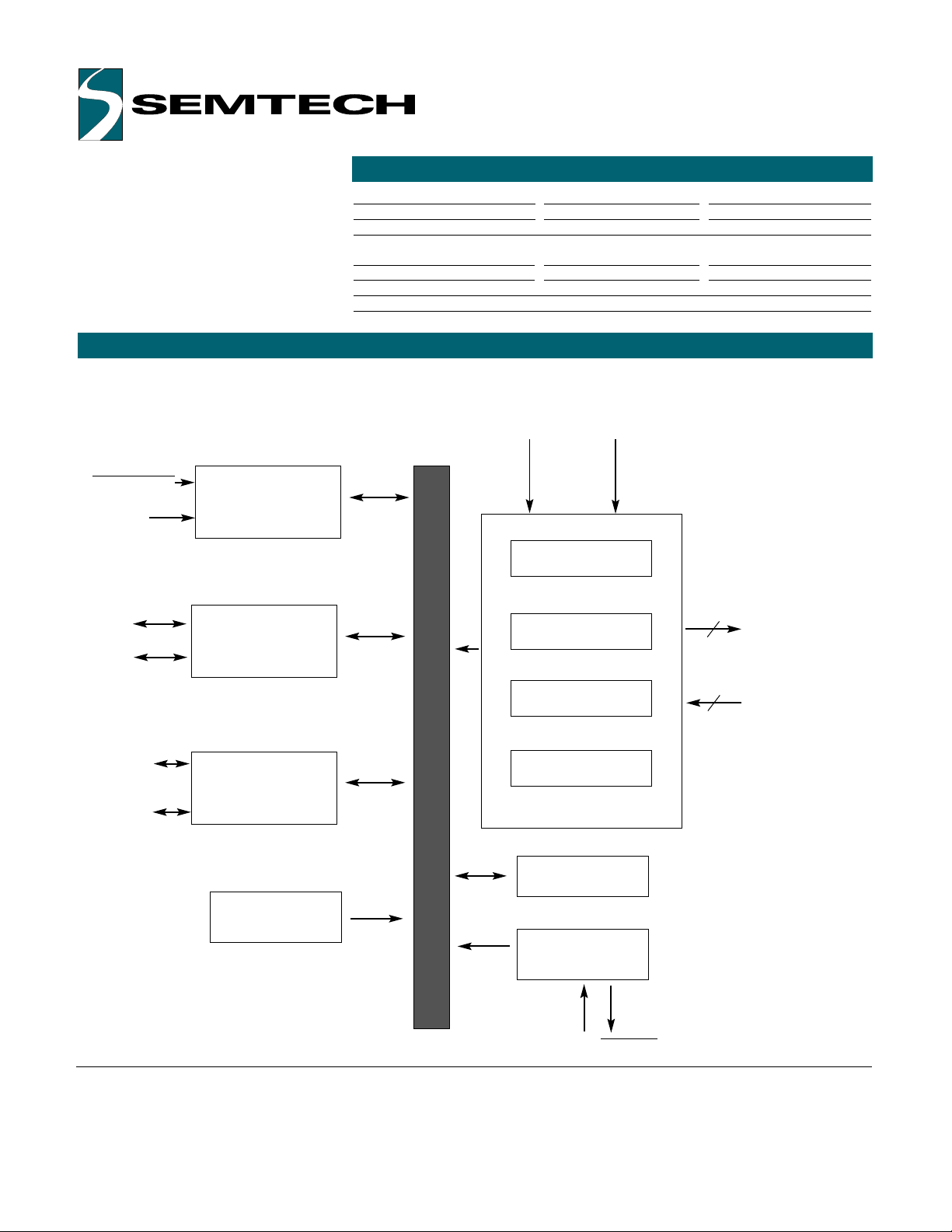
Power Management
PS/2 Communication Port
8042 Emulation Port
PWR_DOWN
XPWRS
HCLK
HDAT
XCLK
XDAT
Sensor Interface
Oscillator Circuit
Power-On Reset
Switch Interface
X Input
Y Input
Control
OSCOUT
16 bit Timer
Drivers for
Touch Screen
Sensor
Sense Lines
4
Left
Button
Right
Button
4
OSCIN
BLOCK DIAGRAM
Page 3

PIN DEFINITIONS
Copyright ©1999-2001 Semtech Corporation
DOC7-TS2-P840-DS-106
www.semtech.com
3
Mnemonic Pin # Type Name and Function
VDD 8 P Power Supply
VSS 11 P Ground
VSS2 7 P Ground
OSCIN 9 I Oscillator Input: external clock input or one
side of the Ceramic Resonator with built-in Load
Capacitors
_OSCOUT 10 O Oscillator Output: open for external clock
input or other side of the Ceramic Resonator with
built-in Load Capacitors
_RESET 6 I Reset: apply 0V to provide orderly start-up
HDAT 19 I/O (nd) Mouse Data: connects to Host’s data line
HCLK 16 I/O (nd) Mouse Clock: connects to Host’s clock line
XCLK 17 I/O (nd) External Mouse Clock: PS/2 clock signal from
external mouse; keep open if unused
XDAT 18 I/O (nd) External Mouse Data: PS/2 data signal from
external mouse; keep open if unused
_LB 24 I/O (nd) Left Button: active low, strobed sampling
_RB 25 I/O (nd) Right Button: active low, strobed sampling
XR1 12 I/O Sensor’s Excitation Driver: connect to X Right
YB1 13 I/O Sensor’s Excitation Driver: connect to Y Bottom
YT1 14 I/O Sensor’s Excitation Driver: connect to Y Top
XL1 15 I/O Sensor’s Excitation Driver: connect to X Left
XL2 20 I/O Sensor’s Excitation Driver: connect to X Left
YT2 21 I/O Sensor’s Excitation Driver: connect to Y Top
YB2 22 I/O Sensor’s Excitation Driver: connect to Y Bottom
XR2 23 I/O Sensor’s Excitation Driver: connect to X Right
VREF 5 AI Reference Voltage for built-in A/D
SXL 31 AI Sense line: for X Left
SYT 32 AI Sense line: for Y Top
SYB 1 AI Sense line: for Y Bottom
SXR 2 AI Sense line: for X Right
_POWER_ Hardware Power Down: tie high if unused
DOWN 30 I
XPWRS 3 AI External Mouse Power Sense: tie high if unused
and external mouse port is used; tie low if external
mouse port is unused
RSVD1-5 4, 26 I/O Reserved
27-29
Note: An underscore before a pin mnemonic denotes an active low signal.
Pin Types Legend: AI=Analog Input; I=Input; O=Output; I/O=Input or Output;
I/O (nd)=Input or Output with N-channel Open Drain driver
Page 4

FUNCTIONAL DESCRIPTION
Copyright ©1999-2001 Semtech Corporation
DOC7-TS2-P840-DS-106
www.semtech.com
4
The ScreenCoderTMUR7HCTS2-P840 consists functionally of six major sections (see the Functional Diagram on
page 2). These are the Sensor Interface, Power Management section, the 16-Bit Timer, the Oscillator Circuit, the
PS/2 Communication Port and the 8042 Emulation Port. All sections communicate with each other and
operate concurrently.
To obtain position information from
the Resistive Touch Screen Sensor,
the ScreenCoderTMPS2 uses four
internal drivers (two pins for each
driver) and four sensing lines.
During sampling, first the drivers
and sensing lines for X axis are
activated, by setting one X driver
high and the other X driver low;
the drivers for Y axis are set
floating. This action produces a
voltage gradient across the touch
screen's surface in the X direction.
The internal A/D measures both the
voltage across the activated X
plane and the voltage potential
between the planes. Next, the
drivers for the Y axis are activated,
while the drivers for the X axis are
set floating. Again, the internal A/D
measures both voltage across the
activated plane and potential
between the planes. The X and Y
absolute position information is
calculated from these four A/D
measurements.
Before the measurement of X
and Y positions, the ScreenCoder
TM
PS2 checks if there is any touch
pressure applied to the sensor.
Proprietary touch detection
algorithm performs this test very
quickly, accommodating sensors
with various plate-to-plate
capacitances. Actual
measurements are somewhat more
complex and are covered by a US
and international patent currently
pending.
This IC has a built-in Oscillator circuit capable of operations with an
external 4.00 MHz Clock source, or a Ceramic Resonator (preferably with
built-in Load Capacitors). Note that the Crystals can NOT be used. The
ScreenCoder
TM
PS2 frequently switches its Oscillator OFF and ON in order
to operate with the least amount of power consumption. Due to their very
high Q, the Crystal-based oscillators have exceedingly long Start-up times
and can NOT be used with the ScreenCoder
TM
PS2.
SENSOR INTERFACE OSCILLATOR
At start-up, or upon receiving a reset command, the UR7HCTS2-P840 will
wait between 300 and 500 milliseconds before sending an AAh to the Host
followed by a device ID of 00h. The IC will then set itself to its default
values (i.e., Incremental Stream Mode with 1:1 scaling, and a report
rate of 100 Hz). The device will then disable itself until an Enable (F4h)
command is sent from the Host.
PS/2 COMMUNICATION
For every correct command or parameter received from the Host, the
UR7HCTS2-P840 sends an Acknowledge (FAh). If an invalid command or
parameter is received, the UR7HCTS2-P840 issues a Resend Request
(FEh). If an invalid input is again received, the device transmits an Error
Code (FCh) to the Host.
Both Error and Resend Request responses are sent by the device within 25
milliseconds. Host may not issue any new commands until either the
ScreenCoderTMPS2 has responded or until 25 milliseconds have elapsed.
ERROR HANDLING
POWER MANAGEMENT
The ScreenCoderTMPS2 implements two power management methods:
Self-Power Management
TM
and System-coordinated Power Management.
Self-Power Management
Self-Power ManagementTMof the ScreenCoderTMPS2 permits,
independently of any system intervention, the lowest power consumption
possible within the present parameters and conditions of operation.
Through Self-Power ManagementTM, the ScreenCoderTMPS2 is capable of
operating - most of the time - at only 1uA, independently of the state of the
system.
Page 5

POWER MANAGEMENT (CON’T)
POWER MANAGEMENT (CON’T)
Copyright ©1999-2001 Semtech Corporation
DOC7-TS2-P840-DS-106
www.semtech.com
5
During the "Critical suspend", the ScreenCoderTMwill shut down all of the
pointing activities. However, the communications with the Host are still
enabled.
External PS/2 power down
The ScreenCoderTMPS2 monitors the power state of the external PS/2
pointing device through the XPWRS pin. If the IC senses that the external
PS/2 device has been powered-down by the host, it will actively eliminate
shot-through current in the input buffers for the clock and data lines by
driving both low.
The ScreenCoder
TM
UR7HCTS2-P840 will re-initialize the external PS/2
pointing device when the power to the external PS/2 port is restored.
Figure 1: Semtech’s Self-Power ManagementTMState
RUN
STOP
System Request To Send,
Mouse hot plug or Data Packet,
Touch Screen activity,
Button press
1s of inactivity
Critical Suspend
Ext Mouse
power down
Normal State
_PWR_DOWN=0
_PWR_DOWN=1
and XPWRS=1
_PWR_DOWN=0
_PWR_DOWN=1
and XPWRS=1
_PWR_DOWN=1
and XPWRS=0
_PWR_DOWN=1
and XPWRS=0
Figure 2: Semtech’s System-coordinated Power Management
The "Stop" mode is the lowest
power consumption mode. In this
mode, the oscillator is stopped and
the IC consumes only the leakage
current. This is the default mode to
which the IC will revert when it is
idle. An event or signal conditions
wake-up the IC. The
ScreenCoderTMPS2 can still
operate most of the time at only
1uA, even when the host is in the
active state, and with active
external PS/2 device attached to
the ScreenCoderTMPS2. If an
external PS/2 device sends a data
packet, the ScreenCoderTMPS2 will
exit the "Stop" mode for as long as
it takes to process the message
and relay the information to the
system. This operation is done
transparently to the host, without
any data loss or any response
delay from the input device.
System-coordinated Power
Management
Normal Operation State
In normal operation state, both
_PWR_DOWN and XPWRS pins are
in high state. ScreenCoderTMPS2
operations are controlled by SelfPower ManagementTM.
Critical Suspend
At any time, the Host may negate
the _PWR_DOWN pin in order to
force the ScreenCoderTMPS2 into a
"Critical suspend" mode. This
signal can be activated (driven
low) due to specific conditions of
the Host's operations (for example,
a discharged battery), or due to
actions of the Operating System or
BIOS.
Page 6

Copyright ©1999-2001 Semtech Corporation
DOC7-TS2-P840-DS-106
www.semtech.com
6
PS/2 DATA FORMAT DATA REPORT FORMAT TABLE
The following table shows the data
report format. X and Y values are
expressed as 9-bit Two’s
Complement signed integers, with
the sign bit / most significant bit
separate. If there is an overflow of
the accumulator, the maximum
positive or negative count is
reported and the corresponding
overflow bit is set.
Byte 1
b0 Left Button status 1 = depressed
b1 Right Button Status 1 = depressed
b2 Middle Button Status 1 = depressed
b3 Reserved Always = 1
b4 X8: MSb of X data, sign bit 1 = negative
b5 Y8: MSb of Y data, sign bit 1 = negative
b6 X data overflow 1 = overflow
b7 Y data overflow 1 = overflow
Byte 2
b0 X0: LSb of X data
b1 X1
b2 X2
b3 X3
b4 X4
b5 X5
b6 X6
b7 X7:
Byte 3
b0 Y0: LSb of Y data
b1 Y1
b2 Y2
b3 Y3
b4 Y4
b5 Y5
b6 Y6
b7 Y7:
Byte 4 (only for Wheelmouse-type devices)
b0 Z0: LSb of Z data
b1 Z1
b2 Z2
b3 Z3
b4 Z4
b5 Z5
b6 Z6
b7 Z7: MSb of Z data
Byte 1
b0 Right Button 1 = depressed
b1 Middle Button 1 = depressed
b2 Left Button 1 = depressed
b3 Reserved Always = 0
b4 Scaling - 1:1 (0) / 2:1 (1)
b5 Disable - (0) / enable (1)
b6 Stream - (0) / prompt (1) mode
b7 Always = 0
Byte 2
b0 - 1 Current resolution setting
b2 - 7 Always = 0
Byte 3
b0-7 Current sampling rate
Semtech offers a high-performance
driver for Windows 95, Windows 98,
Windows Me, and Windows NT.
Please check with Semtech for other
driver availability.
Those that wish to undertake their
own driver development will need to
request from Semtech the document
covering the extended PS/2 protocol
used by the UR7HCTS2-P840.
EXTENDED PS/2 PROTOCOL
STATUS REPORT FORMAT TABLE
Page 7

Copyright ©1999-2001 Semtech Corporation
DOC7-TS2-P840-DS-106
www.semtech.com
7
PS/2 MODE COMMANDS
The Read Report Command
(EBh)
prompts the ScreenCoder
TM
PS2 for a report. The report occurs
even if the device has not moved
or if the status of the switches did
not change.
The Set Incremental Stream
Mode Command (EAh)
sets the
ScreenCoderTMPS2 to Stream
Mode and disables the device.
The Status Request Command
(E9h)
returns a 3-byte status
report.
The Set Resolution Command
(E8h)
controls resolution, the Set
2:1 Scaling Command (E7h)
enables a coarse/fine tracking
response, and the Set 1:1 Scaling
Command (E6h)
enables the
values of movements to be
transmitted to the Host without any
scaling. Due to Semtech’s
Advanced Motion Algorithm, Set
Resolution and Scaling Commands
are acknowledged and reported as
activated, but their status is
ignored.
When the Reset Command (FFh)
is received, the UR7HCTS2-P840
sets the following default
parameters: Incremental Stream
Mode, 1:1 scaling, report rate of
100 Hz, and disabled. It then
sends AAh to the host followed by
a device ID of 00h.
The Host sends the Resend Last
Data Stream Command (FEh)
when the host detects an error in
any UR7HCTS2-P840 transmission.
The device then resends the last
output data packet to the Host.
This transmission occurs after a
ScreenCoderTMPS2 transmission
and before the Host enables the
interface allowing the next
ScreenCoderTMPS2 output.
The Set Default Status
Command (F6h)
re-initializes the
device to its condition at power-up.
The Disable Command (F5h)
stops the device from transmitting
all reports. However, the mode
does not change; the
ScreenCoderTMPS2 is still able to
respond to commands. If the
Disable Command is issued while
the device is transmitting a report,
the UR7HCTS2-P840 immediately
stops the transmission and
disables itself.
The Reset Echo Mode Command
(ECh)
returns the device to its
previous mode, and disabled.
The Set Prompt (Remote) Mode
Command (F0h)
sets the device
to Prompt Mode. Data values are
then only reported in response to a
Read Report Command (EBh).
If the Set Echo Mode Command
(EEh)
is received, the
ScreenCoderTMPS2 will
immediately return any data bytes
except FFh or ECh.
If the ScreenCoderTMPS2 is in
Incremental Stream Mode, the
Enable Command (F4h) will allow
it to begin data transmission. If the
device is in Prompt Mode, the
Enable Command will only update
the internal status of the
ScreenCoderTMPS2.
The ScreenCoderTMPS2 will
respond to the Set Sampling
Rate Command (F3h)
in both
Stream and Prompt Modes but will
only update its internal status if this
command is enacted while the
device is in the Stream Mode.
The UR7HCTS2-P840 responds to
the Read Device Type Command
(F2h)
with the device ID of 00h.
Page 8

Copyright ©1999-2001 Semtech Corporation
DOC7-TS2-P840-DS-106
www.semtech.com
8
SEQUENTIAL COMMANDS
Unlike normal commands, sequential commands must be enacted with a
sequence of commands. If the sequence is not consecutive or is incorrect,
the ScreenCoderTMPS2 aborts the detection and responds the way it would
normally respond to a command.
The individual commands that comprise a sequential command have been
designed so that the elements of a sequential command can be sent to the
ScreenCoderTMPS2 via the standard IBM PS/2 BIOS calls and the device
returns a valid response to the Status Request. This ensures that, if the
sequential command is sent via the BIOS, the status response will be
accurately returned even if the BIOS performs error detection. Thus, a
programmer can have complete control of the mouse without having to
access the device hardware port directly.
The UR7HCTS2-P840 implements a special sequential command that can
be used to determine its ability to report three buttons. The sequential
command is a series of commands to the ScreenCoderTMPS2 that cause
the device to respond to the last command (Read Status) with alternate
information.
The sequence of commands is as follows.
1. Set Resolution = one count/ mm (E8H)
2. Set Scaling = 1:1 (E6H)
3. Set Scaling = 1:1 (E6H)
4. Set Scaling = 1:1 (E6H)
5. Read Status (E9H)
The response to the Read Status Command is in the following format.
Byte 1: Standard Status Information (buttons, scaling, etc.)
Byte 2: Number of mouse buttons (3)
Byte 3: Firmware Revision Number (encoded) or current sampling rate
Page 9

Copyright ©1999-2001 Semtech Corporation
DOC7-TS2-P840-DS-106
www.semtech.com
9
SCREENCODERTMPS2 ABSOLUTE AND RELATIVE POSITIONING MODES OF OPERATION
The ScreenCoderTMPS2 supports both absolute and relative positioning modes. Details on how to use the IC in
each mode are specified below.cri
In relative positioning mode, the ScreenCoderTMPS2 operates like a normal
mouse, using a standard system mouse driver.
Button functionality can be achieved as follows: actual switches will act as
left and right buttons, or a tap on the screen will act as a left-button click.
By tapping on the touchscreen, the user can invoke click, double-click, and
click-and-drag functions.
To click, lightly and quickly tap the surface of the touchscreen once.
To double click, rapidly tap on the touchscreen twice.
To click and drag, double-tap rapidly and hold your finger down on the
second tap, then glide to move.
To enable the ScreenCoderTMPS2
to operate in an absolute
positioning mode, a ScreenCoder
TM
PS2 driver, or a driver compliant to
the Semtech’s Extended PS/2
protocol, must be installed.
ScreenCoderTMPS2 drivers are
available for use under Windows
95, Windows 98, Windows Me, and
Windows NT. Other operating
systems are also supported;
please call Semtech for details.
For Commands and Data Report
organization, please refer to the
Semtech Extended PS/2 Protocol
with Absolute Positioning Mode
Support
document.
ABSOLUTE POSITIONING MODE RELATIVE POSITIONING MODE
Page 10

Copyright ©1999-2001 Semtech Corporation
DOC7-TS2-P840-DS-106
www.semtech.com
10
SUGGESTED INTERFACING FOR THE SCREENCODER
TM
PS2 UR7HCTS2-P840-FG
UR7HCTS2P840 Rev 0.8
ScreenCoder II UR7HCTS2-P840-FG
Ph 212.226.2042 Fax 212.226.3215
NEW YORK, NY 10012
568 BROADWAY
(C)2000 USAR Systems, A Semtech Company
6
4
2
5
3
1
78
JP3
MDIN6_SH
L1
12uH
C7
47pF
EXT_PS2_VDD
M_DATA
EXT_M_CLOCK
EXT_M_DATA
XL
YB
YT
XR
GND
SW2
RIGHT BUTTON
GND
SW1
LEFT BUTTON
DRV_XL
DRV_YB
DRV_YT
DRV_XR
SENSE_XL
See Notes
SENSE_YB
SENSE_YT
SENSE_XR
PWR_ON
S
Y
B
1
S
X
R
2
X
P
W
R
S
3
R
S
V
D
1
4
V
R
E
F
5
R
E
S
E
T
6
V
S
S
2
7
V
D
D
8
OSCIN
9
OSCOUT
10
VSS
11
XR1
12
YB1
13
YT1
14
XL1
15
HCLK
16
X
C
L
K
1
7
X
D
A
T
1
8
H
D
A
T
1
9
X
L
2
2
0
Y
T
2
2
1
Y
B
2
2
2
X
R
2
2
3
L
B
2
4
RB
25
RSVD2
26
RSVD3
27
RSVD4
28
RSVD5
29
PWR_DOWN
30
SXL
31
SYT
32
U1
UR7HCTS2_P840
32-pin LQFP
Y1
4.00MHz
M_CLOCK
Mounting
holes
GND
C8
47pF
PS/2 DATA
SHIELD
GND
+5V
PS/2CLOCK
1
2
3
4
5
JP2
S5B_PH_K
M_DATA
M_CLOCK
VDD
GND
1
2
3
U2
TC54VC4502ECB
C2
10uF
VDD
VDD
GND
GND
C3-C6 10nF +/-10% CERAMIC X7R
C1 .1uF ANY CERAMIC ANY
REF VALUE TOLERANCE OTHER DATA
C1
.1uF
GND GND
SXL
SYT
1357
8642
RN1
10k
C3
10nF
+/-10% X7R
C4
10nF
+/-10% X7R
SYB
SXR
NOTES:
GND
Connect Drive and Sense lines together for the 4-wire Sensor.
Y1 == 4.00 MHz Ceramic Resonator with Built-in Load Capacitors.
P840 == PS/2 In/Out, 4.00 MHz, 8/4-wire, Model 0.
Crystals can NOT be used.
C5
10nF
+/-10% X7R
C6
10nF
+/-10% X7R
NOT_RESET
EXT_POWER_SENSE
GND
EXT_PS2_VDD
RN1 10K +/-5% ANY
Y1 4.00 MHz PBRC-4.00BR, AVX
REF VALUE PART#, MFG
Page 11

Copyright ©1999-2001 Semtech Corporation
DOC7-TS2-P840-DS-106
www.semtech.com
11
SCREENCODERTMPS2 EVALUATION BOARD MECHANICAL
Page 12

Copyright ©1999-2001 Semtech Corporation
DOC7-TS2-P840-DS-106
www.semtech.com
12
SUGGESTED EVALUATION BOARD INTERFACING FOR THE SCREENCODERTMPS2 UR7HCTS2-P840-FG
UR7HCTS2EVB.sch Rev 0.8
EVB for ScreenCoder II UR7HCTS2-P840-FG
Ph 212.226.2042 Fax 212.226.3215
NEW YORK, NY 10012
568 BROADWAY
(C)2000 USAR Systems, A Semtech Company
6
4
2
531
78
JP3
MDIN6_SH
L1
12uH
C7
47pF
GND
VDD
1
2
3
JP5
CON_SIP3
M_DATA
EXT_M_CLOCK
EXT_M_DATA
X_PS2_PWR
123
JP6
CON_SIP3
GND
SW2
RIGHT BUTTON
GND
SW1
LEFT BUTTON
Y_T
SYT
X_L
SXL
Y_B
SYB
123456789
10
JP1
CON_2X5
SEE NOTES
X_R
SXR
GND
GND
VDD
123
JP4
CON_SIP3
GND
VDD
1234567
8
JP7
CON_SIP8
SYB
1
SXR
2
XPWRS
3
RSVD1
4
VRE
F
5
RESET
6
VSS
2
7
VDD
8
OSCIN
9
OSCOUT
10
VSS11XR112YB1
13
YT114XL1
15
HCLK
16
XCL
K
1
7
XDA
T
1
8
HDA
T
1
9
XL2
2
0
YT2
2
1
YB2
2
2
XR2
2
3
L
B
2
4
RB
25
RSVD2
26
RSVD3
27
RSVD4
28
RSVD5
29
PWR_DOWN
30
SXL
31
SYT
32
U1
UR7HCTS2_P840
32-pin LQFP
Y1
4.00MHz
M_CLOCK
GND
Mounting
holes
GND
C8
47pF
PS/2 DATA
SHIELD
GND
+5V
PS/2CLOCK
1
2
3
4
5
JP2
S5B_PH_K
M_DATA
M_CLOCK
VDD
GND
C1
.1uF
C2
10uF
VDD
VDD
GND
GND GND
1
2
3
U2
TC54VC4502ECB
C3-C6 10nF +/-10% CERAMIC X7R
C1 .1uF ANY CERAMIC ANY
REF VALUE TOLERANCE OTHER DATA
NOT_RESET
GND
FXL
FYT
C3
10nFC410nF
1357
8642
RN1
10k
FYB
FXR
NOTES:
GND
C5
10nFC610nF
The PCB is pre-configured for the 4-wire Sensor. For the 8-wire Sensor
cut the jumpers beteen the Drive and the Sense lines, change JP1.
P840 == PS/2 In/Out, 8/4-wire, 4.00 MHz, Model 0.
Traces of the jumpers are located on the Bottom (Solder) side of the PCB,
between the pins of JP1.
GND
RN1 10K +/-5% ANY
Y1 4.00 MHz PBRC-4.00BR/AVX
REF VALUE PART NUMBER/MFG
Page 13
Copyright ©1999-2001 Semtech Corporation
DOC7-TS2-P840-DS-106
www.semtech.com
13
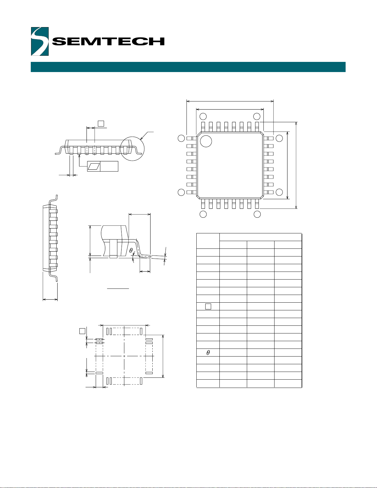
MECHANICAL INFORMATION FOR THE FG PACKAGE
e
F
y
b
HD
D
32 25
1
24
E
E
H
8
L1
c
A1 A2
L
9
Symbol
A
A1
2
A
16
Dimension in Millimeters
Min Nom Max
–
0
––
0.1
1.4
b
M
M
c
D
E
e
D
H
E
H
–
0.8
L
1
L
y
b
2
I
2
D
E
––
–
1.0
1.0
0.5
7.4
7.4
Detail F
A
M
D
e
ME
b2
I2
17
–
1.7
0.2
0.450.350.3
0.1750.1250.105
7.17.06.9
7.17.06.9
–
9.29.08.8
9.29.08.8
0.70.50.3
–
–
0.1
10ϒ0ϒ
––
––
––
––
Recommended PCB Footprint
Page 14
Copyright ©1999-2001 Semtech Corporation
DOC7-TS2-P840-DS-106
www.semtech.com
14
ELECTRICAL SPECIFICATIONS
Absolute Maximum Ratings
Ratings Symbol Value Unit
Supply Voltage Vdd -0.3 to 7.0 V
Input Voltage Vin Vss -0.3 to Vdd +0.3 V
Current Drain per Pin I 20 mA
(not including Vss or Vdd)
Operating Temperature Ta T low to T high ° C
UR7HCTS2-P840 -20 to +85 ° C
Storage Temperature Range Tstg -40 to +125 ° C
DC Electrical Characteristics, Temperature range=T low to T high unless otherwise noted)
Characteristic Symbol Min Typ Max Unit
Supply Voltage 3.0 5.0 5.5 V
Output Voltage (10 µA load) Voh Vdd–0.1 V
Vol 0.1
Input High Voltage Vih 0.8 x Vdd Vdd V
Input Low Voltage Vil Vss 0.2xVdd V
Input Current Iin +/- 10 µA
Supply Current
(Vdd=5.0 Vdc+/-10%, Vss=0) Idd 3.0 TBD mA
Control Timing (Vdd=5.0 Vdc +/-10%, Vss=0 Vdc, Temperature range=T low to T high unless otherwise noted)
Characteristic Symbol Min Typ Max Unit
Frequency of Operation fosc MHz
Crystal Option 4.0
External Clock Option 4.0
Page 15

Copyright ©1999-2001 Semtech Corporation
DOC7-TS2-P840-DS-106
www.semtech.com
15
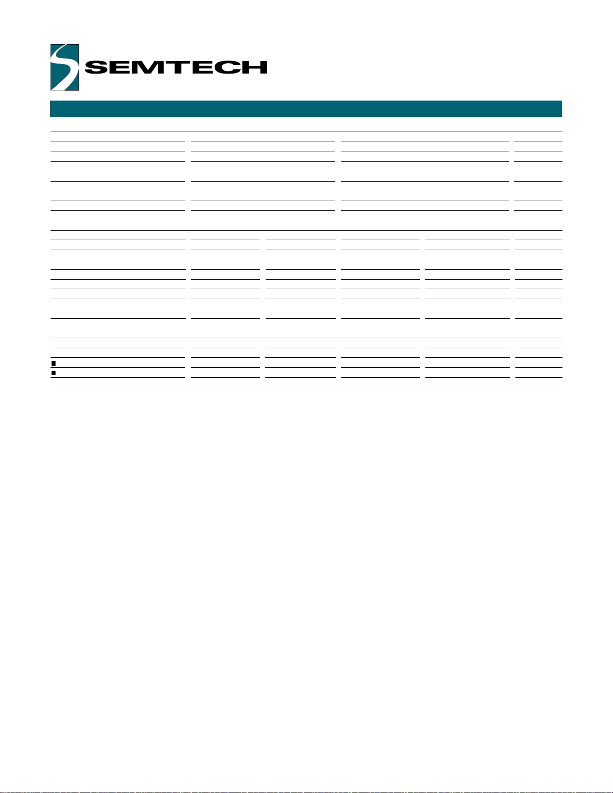
SCREENCODERTMPS2 BILL OF MATERIALS FOR PAGE 10 SCHEMATIC
UR7HCTS2-P840-FG BOM
Description Quantity Manufacturer Part# Description
Capacitors:
C1 1 Generic Any .1uF, 10%, Ceramic, X7R or Z5U
C2 1 Generic Any 10uF, 10V, +80%/-20%, Tantalum
C3, C4, C5, C6 4 Generic Any 10nF, 10%, Ceramic, X7R
C7, C8 2 Generic Any 47pF, 10%, Ceramic, X7R
ICs:
U1 1 Semtech UR7HCTS2-P840-FG ScreenCoderTMPS/2 Controller
U2 1 Telcom TC54VC4502ECB Reset IC
Resistor
Network
RN1 1 Generic Any 10K, 4 independent resistors
Resonator:
Y1 1 AVX PBRC-4.00BR 4.00MHz Ceramic Resonator w/ Caps, SMT
Inductor
L1 1 Generic Any 12uH Inductor
NNoottee::
Auxillary components are not shown.
Page 16

Copyright ©1999-2001 Semtech Corporation
DOC7-TS2-P840-DS-106
www.semtech.com
16
For sales information
and product literature,
contact:
HID & System Mgmt Division
Semtech Corporation
568 Broadway
New York, NY 10012
hidinfo@semtech.com
http://www.semtech.com
212 226 2042 Telephone
212 226 3215 Telefax
Semtech Western Regional Sales
805-498-2111 Telephone
805-498-3804 Telefax
Semtech Central Regional Sales
972-437-0380 Telephone
972-437-0381 Telefax
Semtech Eastern Regional Sales
203-964-1766 Telephone
203-964-1755 Telefax
Semtech Asia-Pacific Sales Office
+886-2-2748-3380 Telephone
+886-2-2748-3390 Telefax
Semtech Japan Sales Office
+81-45-948-5925 Telephone
+81-45-948-5930 Telefax
Semtech Korea Sales Sales
+82-2-527-4377 Telephone
+82-2-527-4376 Telefax
Northern European Sales Office
+44 (0)2380-769008 Telephone
+44 (0)2380-768612 Telefax
Southern European Sales Office
+33 (0)1 69-28-22-00 Telephone
+33 (0)1 69-28-12-98 Telefax
Central European Sales Office
+49 (0)8161 140 123 Telephone
+49 (0)8161 140 124 Telefax
Copyright ©1999-2001 Semtech Corporation. All rights reserved.
MouseCoder, ScreenCoder and Self-Power Management are
trademarks of Semtech Corporation. Semtech is a registered
trademark of Semtech Corporation. All other trademarks belong to
their respective companies.
INTELLECTUAL PROPERTY DISCLAIMER
This specification is provided "as is" with no warranties whatsoever
including any warranty of merchantability, fitness for any particular
purpose, or any warranty otherwise arising out of any proposal,
specification or sample. A license is hereby granted to reproduce
and distribute this specification for internal use only. No other
license, expressed or implied to any other intellectual property
rights is granted or intended hereby. Authors of this specification
disclaim any liability, including liability for infringement of proprietary
rights, relating to the implementation of information in this
specification. Authors of this specification also do not warrant or
represent that such implementation(s) will not infringe such rights.
 Loading...