

Datasheet ULQ2004D1, ULQ2004A, ULQ2003D1, ULQ2003A, ULQ2002D1 Datasheet (SGS Thomson Microelectronics)
...Page 1
ULQ2 002A - ULQ2 004A
ULQ200 1A - ULQ 200 3A
April1993
SEVEN DARLINGTON ARRAYS
.SEVENDARLINGTONS PER PACKAGE
.EXTENDEDTEMPERATURE RANGE
(–40to 105°C)
.OUTPUT CURRENT 500 mA PER DRIVER
(600mA PEAK)
.OUTPUTVOLTAGE50 V
.INTEGRAL SUPPRESSION DIODES FOR IN-
DUCTIVELOADS
.OUTPUTS CAN BE PARALLELED FOR
HIGHER CURRENT
.TTL/CMOS/PMOS/DTLCOMPATIBLE INPUTS
.INPUTS PINNED OPPOSITE OUTPUTS TO
SIMPLIFYLAYOUT
DESCRIP TION
The ULQ2001A, ULQ2002A, ULQ2003 and
ULQ2004Aare highvoltage,highcurrentdarlington
arrays each containing seven open collector darlingtonpairswithcommonemitters.Eachchannelis
ratedat500mA and canwithstandpeakcurrentsof
600mA.Suppressiondiodesareincludedfor inductiveloaddrivingand the inputsare pinnedopposite
the outputstosimplify boardlayout.
Thefourversionsinterfacetoallcommonlogicfamilies :
ULQ2001A General Purpose, DTL, TTL, PMOS,
CMOS
ULQ2002A 14-25V PMOS
ULQ2003A 5V TTL, CMOS
ULQ2004A 6-15V CMOS, PMOS
Theseversatiledevicesareusefulfor drivingawide
range of loads including solenoids, relaysDC motors, LED displays filament lamps, thermal printheadsand high power buffers.
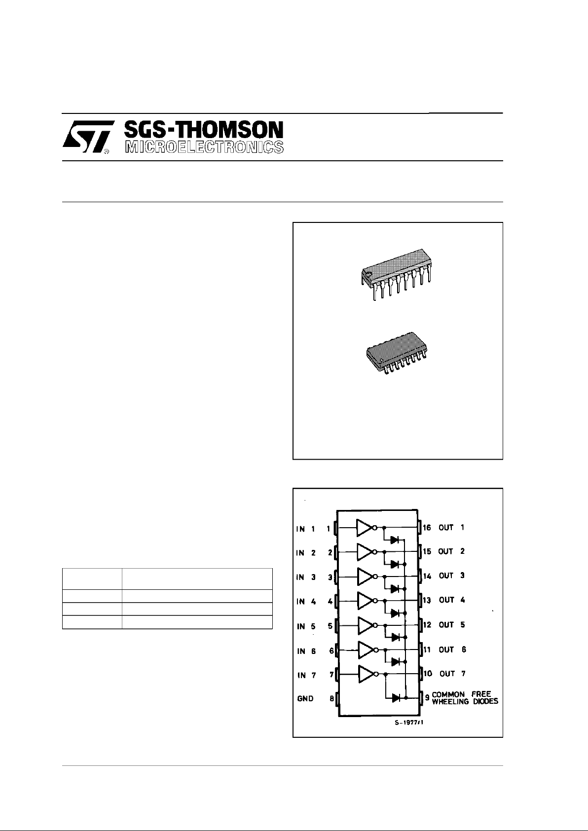
TheULQ2001A/2002A/2003Aand 2004A are suppliedin 16 pin plastic DIP packageswith a copper
leadframe to reduce thermal resistance. They are
availablealso in small outline package (SO-16)as
ULQ2001D1/2002D1/2003D1/2004D1.
DIP 16
SO16
ORDERINGNUMBERS:
ULQ2001A/2A/3A/4A (DIP16)
ULQ2001D1/2D1/3D1/4D1 (SO16)
PIN CONNECTION
1/7
Page 2
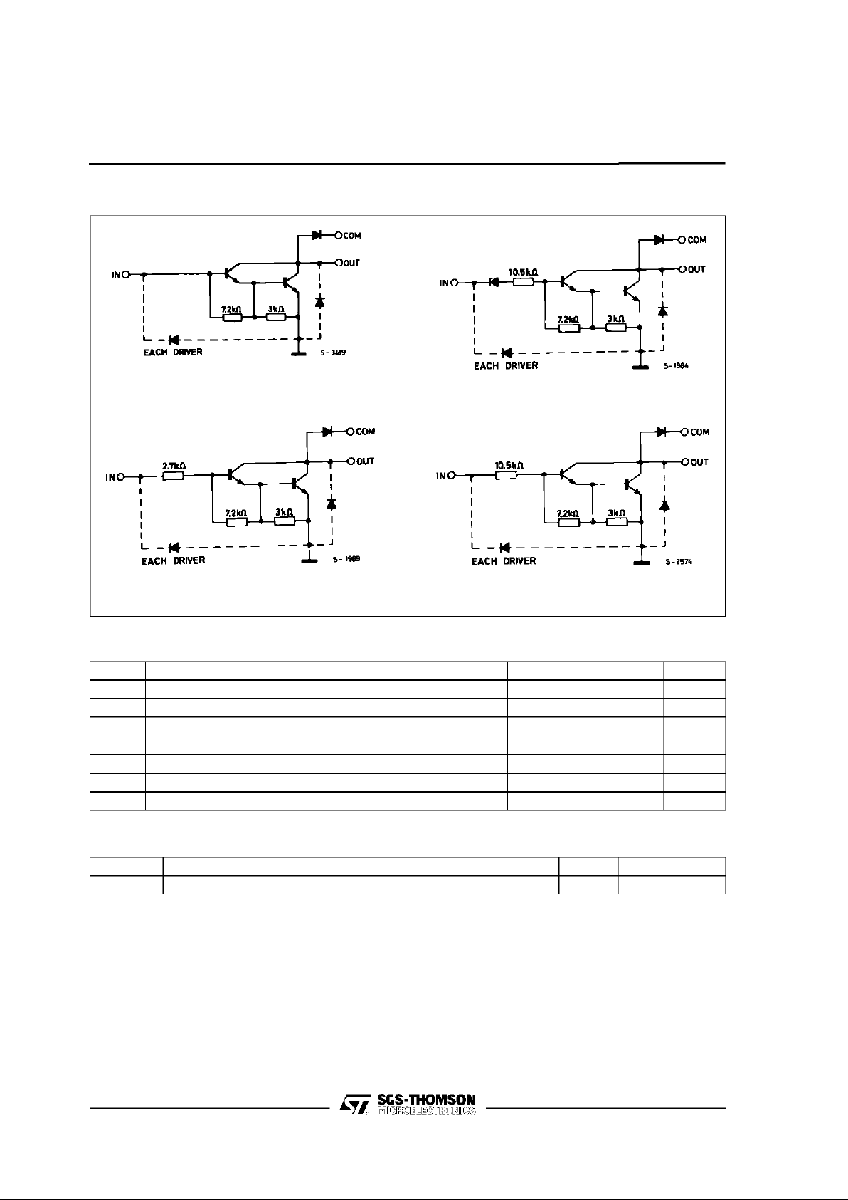
SCHEMATIC DIAGRAM
SeriesULQ-2001A
(each driver)
SeriesULQ-2002A
(each driver)
SeriesULQ-2003A
(each driver)
SeriesULQ-2004A
(each driver)
ABSOLUTE MAXIMUM RATINGS
Symbol Parameter Value Unit
V
o
Output Voltage 50 V
V
in
Input Voltage (for ULQ2002A/D1 - 2003A/D1 - 2004A/D1) 30 V
I
c
Continuous Colletor Current 500 mA
I
b
Continuous Base Current 25 mA
Tamb
Operating Ambient Temperature Range –40 to 105 °C
T
stg
Storage Temperature Range –55 to 150 °C
T
j
Junction Temperature 150 °C
THERMAL DATA
Symbol Parameter DIP16 SO16 Unit
R
th j-amb
Thermal Resistance Junction-ambient Max. 70 165 °C/W
ULQ2001A - ULQ2002A - ULQ2003A - ULQ2004A
2/7
Page 3
ELECTRICAL CHARACTERISTICS (TJ= –40 to 105oC for DIP16 unless otherwise specified)
(T
J
= 25 to 105oC for SO16 unless otherwise specified)
Symbol Parameter Test Conditions Min. Typ. Max. Unit Fig.
I
CEX
Output Leakage Current VCE= 50V
T
J
= 105°C, VCE= 50V
T
J
= 105°C
for ULQ2002A V
CE
= 50V, Vi=6V
for ULQ2004A V
CE
= 50V, Vi=1V
50
100
500
500
µA
µA
µA
µA
1a
1a
1b
1b
V
CE(sat)
Collector-emitter
Saturation Voltage
IC= 100mA, IB= 250µA
I
C
= 200mA, IB= 350µA
I
C
= 350mA, IB= 500µA
0.9
1.1
1.3
1.1
1.3
1.6
V
V
V
2
2
2
I
i(on)
Input Current for ULQ2002A Vi= 17V
for ULQ2003A V
i
= 3.85V
for ULQ2004A V
i
=5V
V
i
= 12V
0.82
0.93
0.35
1
1.25
1.35
0.5
1.45
mA
mA
mA
mA
3
3
3
3
I
i(off)
Input Current TJ= 105°C, IC= 500µA5065µA4
V
i(on)
Input Voltage for ULQ2002A VCE= 2V, IC= 300mA
for ULQ2003A V
CE
= 2V, IC= 200mA
V
CE
= 2V, IC= 250mA
V
CE
= 2V, IC= 300mA
for ULQ2004A V
CE
= 2V, IC= 125mA
V
CE
= 2V, IC= 200mA
V
CE
= 2V, IC= 275mA
V
CE
= 2V, IC= 350mA
13
2.4
2.7
3
5
6
7
8
V
V
V
V
V
V
V
V
5
5
5
5
5
5
5
5
h
FE
DC Forward Current Gain for ULQ2001A VCE= 2V, IC= 350mA 1000 – 2
C
i
Input Capacitance 15 25 (*) pF –
t
PLH
Turn-on Delay Time 0.5 Vito 0.5 V
o
0.25 1 (*) µs–
t
PHL
Turn-off Delay Time 0.5 Vito 0.5 V
o
0.25 1 (*) µs–
I
R
Clamp Diode Leakage
Current
VR= 50V
T
J
= 105°C, VR= 50V
50
100µAµA66
V
F
Clamp Diode Forward
Voltage
IF= 350mA 1.7 2 V 7
(*) Guaranteed by design
ULQ2001A - ULQ2002A - ULQ2003A - ULQ2004A
3/7
Page 4

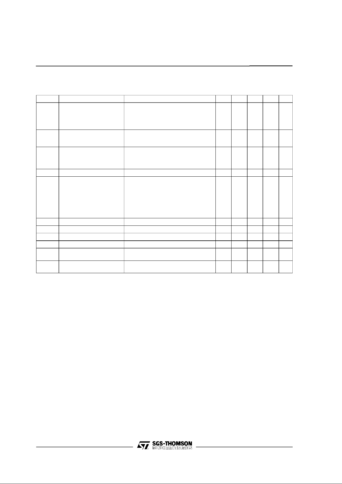
TEST CIRCUITS
Figure 1a. Figure 1b.
Figure 2. Figure 3.
Figure 4. Figure 5.
Figure 6. Figure 7.
ULQ2001A - ULQ2002A - ULQ2003A - ULQ2004A
4/7
Page 5

SO16 PACKAGE MECHANICAL DATA
DIM.
mm inch
MIN. TYP. MAX. MIN. TYP. MAX.
A 1.75 0.069
a1 0.1 0.25 0.004 0.009
a2 1.6 0.063
b 0.35 0.46 0.014 0.018
b1 0.19 0.25 0.007 0.010
C 0.5 0.020
c1 45 (typ.)
D 9.8 10 0.386 0.394
E 5.8 6.2 0.228 0.244
e 1.27 0.050
e3 8.89 0.350
F 3.8 4.0 0.150 0.157
L 0.4 1.27 0.016 0.050
M 0.62 0.024
S 8 (max.)
ULQ2001A - ULQ2002A - ULQ2003A - ULQ2004A
5/7
Page 6

DIP16 PACKAGE MECHANICAL DATA
DIM.
mm inch
MIN. TYP. MAX. MIN. TYP. MAX.
a1 0.51 0.020
B 0.77 1.65 0.030 0.065
b 0.5 0.020
b1 0.25 0.010
D 20 0.787
E 8.5 0.335
e 2.54 0.100
e3 17.78 0.700
F 7.1 0.280
I 5.1 0.201
L 3.3 0.130
Z 1.27 0.050
ULQ2001A - ULQ2002A - ULQ2003A - ULQ2004A
6/7
Page 7

Information furnished is believed to be accurate and reliable. However, SGS-THOMSON Microelectronics assumes no responsibility for
the consequences of use of such information nor for any infringement of patents or other rights of third parties which may result from its
use. No license is granted by implication or otherwise under any patent or patent rights of SGS-THOMSON Microelectronics. Specifications mentioned in this publication are subject to change without notice. This publication supersedes and replaces all information previously supplied. SGS-THOMSON Microelectronics products are not authorized for use as critical components in life support devices or
systems without express written approval of SGS-THOMSON Microelectronics.
1994 SGS-THOMSON Microelectronics - All Rights Reserved
SGS-THOMSON Microelectronics GROUP OF COMPANIES
Australia - Brazil - France- Germany - Hong Kong - Italy - Japan - Korea - Malaysia - Malta - Morocco - The Netherlands - Singapore -
Spain - Sweden - Switzerland - Taiwan - Thaliand - UnitedKingdom - U.S.A.
ULQ2001A - ULQ2002A - ULQ2003A - ULQ2004A
7/7
 Loading...