

Page 1
1
2
3
4
5
611
710
89
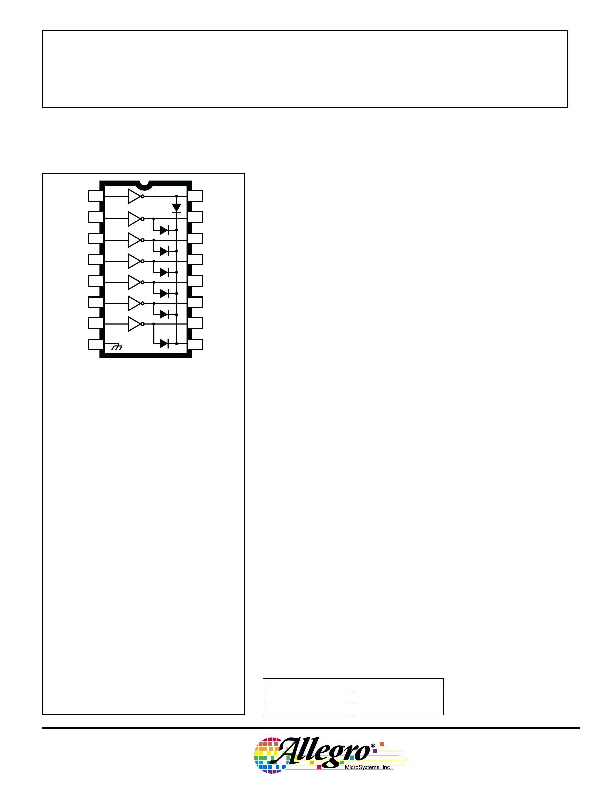
Note the ULN7003A (DIP) and the ULN7003LW
(SOIC) are electrically identical and share a
common terminal number assignment.
16
15
14
13
12
Dwg. No. A-9594
7003
HIGH-VOLTAGE, HIGH-CURRENT
DARLINGTON ARRAY
Integrating seven high-voltage, high-current npn Darlingtons into
a monolithic power array, the ULN7003A AND ULN7003LW are
designed for interfacing between TTL or CMOS logic and a variety of
peripheral loads. The seven open-collector Darlington outputs are
specified for 135 V minimum breakdown and 90 V minimum sustaining. Included are integral power diodes for switching inductive loads.
Typical applications include relays, lamps, print heads and hammers,
solenoids, and level shifting to power discretes.
The ULN7003A/LW include input current-limiting resistors
compatible with the drive capabilities of TTL and (most) CMOS
operating at a nominal logic supply of 5 V. Operation with 12 V
CMOS may require additional input current limiting.
The high sustaining voltage rating of this power array makes it
ideal for inductive load applications where Zener diode flyback techniques are used. The increased flyback voltage provides a much faster
inductive load turn-off current decay that is especially useful with
dc stepper motors, solenoids, and print heads.
Data Sheet
29304.10A
ABSOLUTE MAXIMUM RATINGS
at TA = +25°C
Output Voltage, V
Output Sustaining Voltage,
V
CE(sus)
Output Current, I
Input Current, IIN . . . . . . . . . . . . . . . . 25 mA
Package Power Dissipation,
. . . . . . . . . . . . . . . . . . See Graph
P
D
Operating Temperature Range,
. . . . . . . . . . . . . . . -20°C to +85°C
T
A
Storage Temperature Range,
. . . . . . . . . . . . . . -55°C to +150°C
T
S
Output current may be limited by duty cycle,
number of drivers operating, ambient temperature, and heat sinking. Under any set of
conditions, do not exceed the specified maximum
current rating or a junction temperature of 150°C.
. . . . . . . . . . . . . 135 V
CEX
. . . . . . . . . . . . . . . . . . . 90 V
. . . . . . . . . . . . . . 300 mA
C
— April 2, 2001 —
LAST TIME BUY
Both devices are pinned with outputs opposite inputs to facilitate
ease of circuit board layout. The ULN7003A is supplied in a 16-pin
plastic dual in-line package with a copper lead frame to maximize
device power dissipation capabilities. The ULN7003LW is furnished
in a 16-lead small-outline wide-body package for surface-mount
applications.
FEATURES
■ 135 V Minimum Output Breakdown
■ 90 V Minimum Sustaining Voltage
■ 300 mA Output Current
■ Internal High-Current Clamp Diodes
■ Logic-Compatible Inputs
Always order by complete part number:
Part Number Package
ULN7003A 16-Pin DIP
ULN7003LW 16-Lead SOIC
Page 2
7003
HIGH-VOLTAGE,
HIGH-CURRENT
DARLINGTON ARRAY
2.5
2.0
1.5
1.0
0.5
ALLOWABLE PACKAGE POWER DISSIPATION IN WATTS
SUFFIX 'A', R = 60°C/W
SUFFIX 'LW', R = 80°C/W
0
25
θJA
θJA
50 75 100 125 150
AMBIENT TEMPERATURE IN °C
Dwg. GP-018B
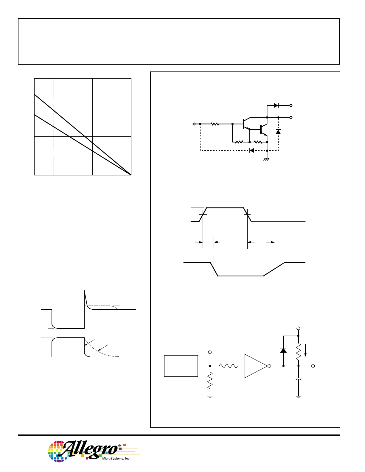
A Zener diode can be used to increase the flyback
voltage. This gives a much faster inductive load turnOFF current decay. The maximum Zener voltage plus
the load supply voltage plus the internal diode forward
voltage must not exceed the device’s rated sustaining
voltage.
PARTIAL SCHEMATIC
(one of seven drivers)
COM
2.7K
7.2K
3K
SWITCHING DELAY TEST CIRCUIT
V
in
0
t
pd
TURN ON TURN OFF
V
out
50%
50%50%
t
pd
50%
Dwg. No. A-9651
OUTPUT
VOLTAGE
OUTPUT
CURRENT
V
V
I
I
CC
CE(SAT)
OUT
CEX
V + V + V
CC Z
ZENER CLAMP
F
V + V
CC F
DIODE CLAMP
Dwg. WP-001
Vin = 3.5 V for ULN7003A
V
in
PULSE
GENERATOR
PRR = 10 kHz
DC = 50%
93 Ω
50 Ω
115 Northeast Cutoff, Box 15036
Worcester, Massachusetts 01615-0036 (508) 853-5000
Copyright © 1985, 2000 Allegro MicroSystems, Inc.
Dwg. WP-010
50 pF
Dwg. No. WP-010
V
CC
I
C
V
out
Dwg. EP-020
Page 3
7003
HIGH-VOLTAGE,
HIGH-CURRENT
DARLINGTON ARRAY
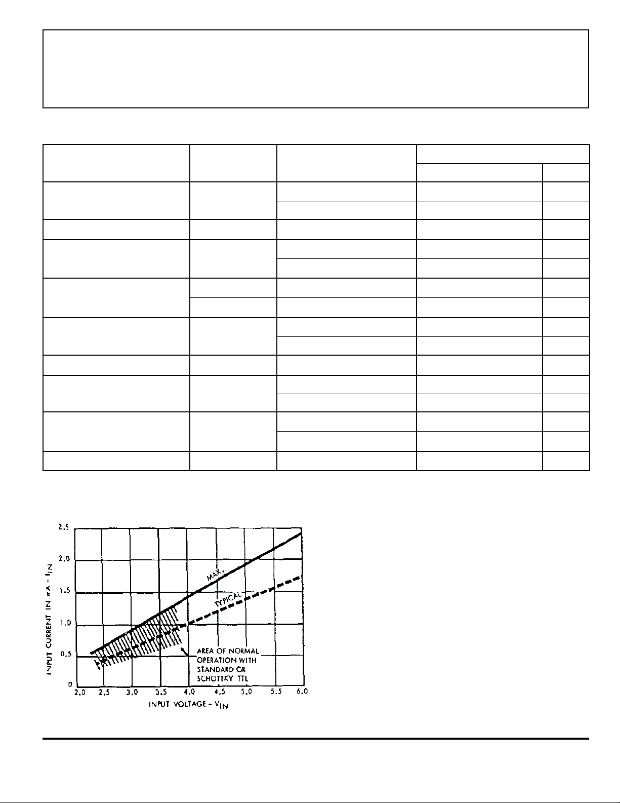
ELECTRICAL CHARACTERISTICS at TA = +25°C (unless otherwise noted).
Limits
Characteristic Symbol Test Conditions Min. Typ. Max. Units
V
Output Leakage Current I
Output Sustaining Voltage V
Output Saturation Voltage V
Input Current I
Input Voltage V
CE(sus)
CE(SAT)
IN(ON)
I
IN(OFF)
IN(ON)
Input Capacitance C
Switching Delay t
Clamp Diode Leakage Current I
Clamp Diode Forward Voltage V
CEX
IN
pd
R
F
= 135 V — — 50 µA
CE
= 135 V, TA = +70°C — — 100 µA
V
CE
IC = 250 mA, L = 2 mH 90 — — V
I
= 100 mA, IIN = 250 µA — 1.1 1.3 V
C
= 250 mA, IIN = 350 µA — 1.3 1.6 V
I
C
V
= 3.85 V — 0.93 1.35 mA
IN
I
= 500 µA, TA = +70°C5065—µA
C
VCE = 2.0 V, IC = 200 mA — — 2.4 V
= 2.0 V, IC = 250 mA — — 2.7 V
V
CE
—1525pF
Turn On, IC = 250 mA — 0.05 1.0 µs
Turn Off, I
V
= 150 V — — 50 µA
R
= 150 V, TA = +70°C — — 100 µA
V
R
I
= 250 mA — 1.7 2.0 V
F
= 250 mA — 0.5 1.0 µs
C
Typical Data is for design information only.
www.allegromicro.com
TYPICAL INPUT CURRENT
AS A FUNCTION OF INPUT VOLTAGE
at TA = +25°C
Page 4

7003
HIGH-VOLTAGE,
HIGH-CURRENT
DARLINGTON ARRAY
ALLOWABLE PEAK COLLECTOR CURRENT AS A
ULN7003A at TA = +50°C ULN7003A at TA = +70°C
FUNCTION OF DUTY CYCLE
300
250
200
150
100
NUMBER OF OUTPUTS
CONDUCTING
SIMULTANEOUSLY
TA = +50°C
θ
JA
= 60°C/W
R
PEAK COLLECTOR CURRENT IN mA
75
10
20
DUTY CYCLE IN PER CENT
ULN7003LW at TA = +50°C
300
250
200
150
NUMBER OF OUTPUTS
CONDUCTING
SIMULTANEOUSLY
4
5
6
7
300
250
200
150
100
NUMBER OF OUTPUTS
CONDUCTING
SIMULTANEOUSLY
TA = +70°C
θ
JA = 60°C/W
R
6
7
3
4
5
PEAK COLLECTOR CURRENT IN mA
75
5030
10070
Dwg. GP-015A
10
20
DUTY CYCLE IN PER CENT
5030
10070
Dwg. GP-015-1A
ULN7003LW at TA = +70°C
300
3
4
5
6
7
250
200
150
NUMBER OF OUTPUTS
CONDUCTING
SIMULTANEOUSLY
3
4
5
6
7
TA = +50°C
θ
JA
= 80°C/W
R
100
PEAK COLLECTOR CURRENT IN mA
75
10
20
DUTY CYCLE IN PER CENT
TA = +70°C
θ
JA
= 80°C/W
R
100
PEAK COLLECTOR CURRENT IN mA
75
5030
10070
10
20
5030
DUTY CYCLE IN PER CENT
Dwg. GP-015-2
10070
Dwg. GP-015-3
115 Northeast Cutoff, Box 15036
Worcester, Massachusetts 01615-0036 (508) 853-5000
Page 5

0.280
0.240
16
ULN7003A
Dimensions in Inches
(controlling dimensions)
9
7003
HIGH-VOLTAGE,
HIGH-CURRENT
DARLINGTON ARRAY
0.014
0.008
0.430
MAX
0.300
BSC
0.210
MAX
7.11
6.10
0.015
MIN
1
0.070
0.045
16
1
1.77
1.15
0.022
0.014
0.100
0.775
0.735
BSC
Dimensions in Millimeters
(for reference only)
2.54
19.68
18.67
BSC
8
0.005
MIN
0.150
0.115
Dwg. MA-001-16A in
0.355
9
8
0.13
MIN
0.204
7.62
BSC
10.92
MAX
5.33
MAX
0.39
MIN
0.558
0.356
NOTES: 1. Lead thickness is measured at seating plane or below.
2. Lead spacing tolerance is non-cumulative.
3. Exact body and lead configuration at vendor’s option within limits shown.
4. Supplied in standard sticks/tubes of 25 devices.
www.allegromicro.com
3.81
2.93
Dwg. MA-001-16A mm
Page 6

7003
HIGH-VOLTAGE,
HIGH-CURRENT
DARLINGTON ARRAY
ULN7003LW
Dimensions in Inches
(for reference only)
16 9
0.0125
0.0091
0.2992
0.2914
0.020
0.013
0.0926
0.1043
7.60
7.40
1 2
0.0040
3
0.4133
0.3977
MIN.
Dimensions in Millimeters
(controlling dimensions)
0.419
0.394
0.050
0.016
0.050
BSC
916
10.65
10.00
0° TO 8°
Dwg. MA-008-16A in
0.32
0.23
0.51
0.33
2.65
2.35
1 2
0.10
MIN.
3
10.50
10.10
1.27
BSC
NOTES: 1. Exact body and lead configuration at vendor’s option within limits shown.
2. Lead spacing tolerance is non-cumulative.
3. Supplied in standard sticks/tubes of 47 devices or add “TR” to part number for tape and reel.
115 Northeast Cutoff, Box 15036
Worcester, Massachusetts 01615-0036 (508) 853-5000
0° TO 8°
1.27
0.40
Dwg. MA-008-16A mm
Page 7

7003
HIGH-VOLTAGE,
HIGH-CURRENT
DARLINGTON ARRAY
www.allegromicro.com
The products described here are manufactured under one or more
U.S. patents or U.S. patents pending.
Allegro MicroSystems, Inc. reserves the right to make, from time to
time, such departures from the detail specifications as may be required
to permit improvements in the performance, reliability, or
manufacturability of its products. Before placing an order, the user is
cautioned to verify that the information being relied upon is current.
Allegro products are not authorized for use as critical components
in life-support devices or systems without express written approval.
The information included herein is believed to be accurate and
reliable. However, Allegro MicroSystems, Inc. assumes no responsibility for its use; nor for any infringement of patents or other rights of
third parties which may result from its use.
Page 8

7003
HIGH-VOLTAGE,
HIGH-CURRENT
DARLINGTON ARRAY
HIGH-VOLTAGE (≥60 V) PERIPHERAL POWER
AND DISPLAY DRIVERS
IN ORDER OF 1) OUTPUT VOLTAGE, 2) OUTPUT CURRENT, 3) NUMBER OF DRIVERS
Output Ratings* Features
Serial Latched Diode Saturated Internal
V mA # Input Drivers Clamp Outputs Protection Part Number †
60 -25 8 – X – – – 5815
-25 10 X X Active Pull-Down – – 5810-F and 6809/10
-25 12 X X Active Pull-Down – – 5811 and 6811
-25 20 X X Active Pull-Down – – 5812-F and 6812
-25 32 X X Active Pull-Down – – 5818-F and 6818
300 4 – – X X X 2557
600 4 – – – X X 2547
600 4 – – X X X 2549
700 4 – – X X X 2559
700 4 – – X X X 2543
4000 4 – – X – – 2944
80 -350 8 – – X – – 2983 and 2984
350 8 X X – – – 5822
350 8 X X X – – 5842
-350 8 X X X – – 5890
1500 4 – – – – – 2065 and 2069
4000 4 – – X – – 2879
85 -25 8 – – – – – 6118
95 300 7 – – X – – 2023
300 8 – – X – – 2823
350 7 – – X – – 2024
350 8 – – X – – 2824
* Current is maximum test condition; voltage is absolute maximum allowable.
Negative current is defined as coming out of (sourcing) the output.
† Complete part number includes additional characters to indicate operating temperature range and package style.
115 Northeast Cutoff, Box 15036
Worcester, Massachusetts 01615-0036 (508) 853-5000
 Loading...