

Datasheet UHR-5-4000-D48, UHR-5-4000-D12, UHR-3.3-4850-D12, UHR-3.3-4850-D48, UHR-15-1300-D48 Datasheet (DATEL)
...Page 1
Single Output
UHR Models
Ruggedized, 2" x 2"
16-20 Watt, DC/DC Converters
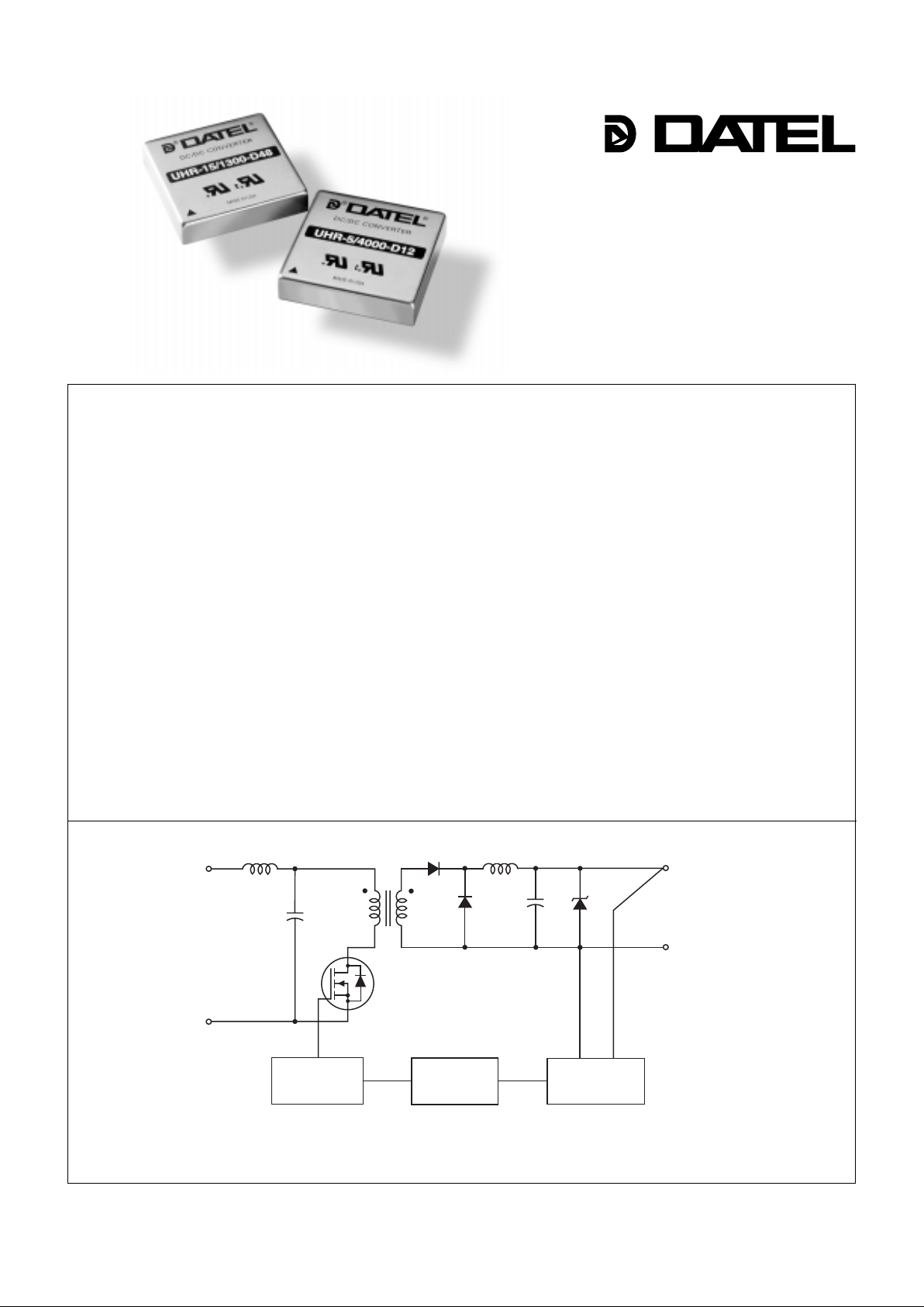
Figure 1. Simplified Schematic
DATEL’s XHR Series DC/DC converters deliver a measure of cost-effective longterm reliability not previously available in commercial, off-the-shelf po wer converters.
These DC/DC’s combine the high-efficiency and wide-input-range of DATEL’s
venerable XWR Series DC/DC’s with a newly developed, all metal-ceramic, construction technique that eliminates the need for thermally-conductive potting compounds.
All electrical components are surface-mount soldered to a 60 mil (0.06"/1.52mm)
ceramic baseplate for low junction-to-case thermal resistance. Package pins, instead
of traditional butt soldering, are soldered through the baseplate via pre-cut holes.
Pre-cutting prior to firing, as opposed to laser cutting after firing, eliminates micro
cracks. The tin plated, steel cover is soldered to the baseplate creating a level of
hermiticity not available in other commercial power modules. The bottom of the
baseplate has a conductive layer that provides 6-sided shielding. It is also insulated
so pc-card runs can pass beneath the package.
UHR Models are the single-output devices in the XHR Series. They offer outputs
of 3.3, 5, 12 or 15 Volts. The ultra-wide (4:1) input voltage ranges are either 9-36V
("D12" models) or 18-72V ("D48" models). Line and load regulation are a tight ±0.3%
max. and ±0.5% max., respectively. All devices guarantee that output ripple/noise will
be less than 100mVp-p. Isolation voltage is guaranteed to be at least 750Vdc.
UHR devices carry industry-standard pinouts in packages whose outside
dimensions are only slightly larger than the 2" x 2" standard. They can be subjected
to mutually-agreed-upon, high-rel screening programs as necessary to satisfy your
system's reliability requirements. Contact DATEL for additional details.
DATEL, Inc., Mansfield, MA 02048 (USA) • Tel: (508)339-3000, (800)233-2765 Fax: (508)339-6356 • Email: sales@datel.com • Internet: www.datel.com
Features
INNOVATION and EX C ELL E N C E
®
®
■
■■
■■
■
■■
■■
■
■■
■■
■
■■
■■
■
■■
■■
■
■■
■■
■
■■
■■
■
■■
■■
■
■■
■■
■
■■
■■
■
■■
■■
■
Ruggedized design
All metal-ceramic construction
Low junction-to-baseplate thermal
impedance
No potting compounds
3.3, 5, 12 or 15 Volt outputs
Ultra-wide input voltage ranges:
9-36V or 18-72V
Industry-standard pinouts
No external components required
Tight regulation, low ripple/noise
Guaranteed efficiencies to 82%
V
OUT trim and on/off control
Modifications and customs for OEM’s
+V
OUT
+V
IN
–
V
IN
REFERENCE &
ERROR AMP
OPTO
ISOLATION
PWM
CONTROLLER
–V
OUT
Page 2
2
Function P6
+Input
–Input
No Pin
On/Off Control
No Pin
+Output
Common
Trim
Pin
1
2
3
4
5
6
7
8
I/O Connections
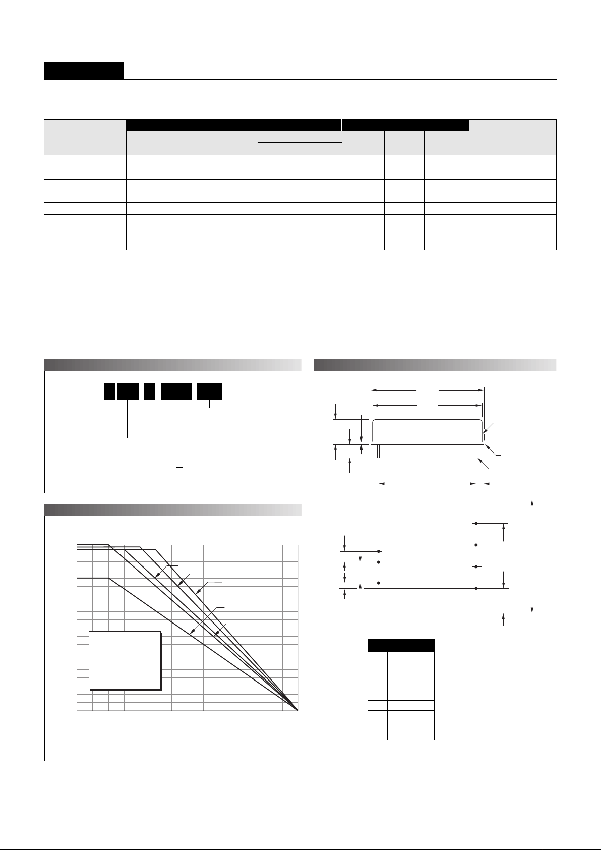
PART NUMBER STRUCTURE
MECHANICAL SPECIFICATIONS
TEMPERATURE DERATING
XHR Series
16-20W, SINGLE OUTPUT DC/DC CONVERTERS
Performance Specifications and Or dering Guide
➀
➀
T ypical at TA = +25°C under nominal line voltage and full-load conditions , unless otherwise noted.
➁
Ripple/Noise (R/N) measured over a 20MHz bandwidth.
➂
20% to 100% load.
➃
Nominal line voltage, no-load/full-load conditions.
UHR-3.3/4850-D12 3.3 4850 75 ±0.5% ±1.0% 24 9-36 45/916 75% C8, P6
UHR-3.3/4850-D48 3.3 4850 100 ±1.0% ±1.0% 48 18-72 25/440 78% C8, P6
UHR-5/4000-D12 5 4000 100 ±0.3% ±0.5% 24 9-36 25/1060 79% C8, P6
UHR-5/4000-D48 5 4000 100 ±0.3% ±0.5% 48 18-72 25/526 80% C8, P6
UHR-12/1650-D12 12 1650 100 ±0.3% ±0.5% 24 9-36 30/1050 81% C8, P6
UHR-12/1650-D48 12 1650 100 ±0.3% ±0.5% 48 18-72 25/514 81% C8, P6
UHR-15/1300-D12 15 1300 100 ±0.3% ±0.5% 24 9-36 30/1000 82% C8, P6
UHR-15/1300-D48 15 1300 100 ±0.3% ±0.5% 48 18-72 30/495 82% C8, P6
Ripple/Noise
➁
(mVp-p, Max.)
VOUT
(Volts)
Package
(Case,
Pinout)
Efficiency
(Min.)
Regulation (Max.)
Line
VIN Nom.
(Volts)
Range
(Volts)Model
IOUT
(mA, Max.)
IIN ➃
(mA, Max.)
Load
➂
Output
Input
Output Power (Watts)
Ambient Temperature (°C)
20
19
18
17
16
15
14
13
12
11
10
9
8
7
6
5
4
3
2
1
0
A
B
–40 0 35 4 0 4 5 5 0 5 5 6 0 6 5 7 0 7 5 8 0 8 5 9 0 9 5
UHR-3.3/4850-D12 A
UHR-3.3/4850-D48 A
UHR-5/4000-D12 B
UHR-5/4000-D48 B
UHR-12/1650-D12 C
UHR-12/1650-D48 C
UHR-15/1300-D12 D
UHR-15/1300-D48 E
C
E
D
Output Configuration:
U = Unipolar
Nominal Output Voltage:
3.3, 5, 12 or 15 Volts
Maximum Output Current
in mA
Input V oltage Range:
D12 = 9-36 Volts (24V nominal)
D48 = 18-72 Volts (48V nominal)
Metal-Ceramic Construction
Wide Range Input
5U HR 4000 D12-/ -
0.040 ±0.002 DIA.
(1.016 ±0.051)
2.00
(50.80)
0.45
(11.43)
0.30
(7.62)
BOTTOM VIEW
1.800
(45.72)
0.400
(10.16)
1
2
4
8
5
6
7
METAL CASE
CERAMIC
BASEPLATE
2.06
(52.32)
2.06
(52.32)
0.06
(1.52)
0.13
(3.30)
0.43
(10.92)
1.200
(30.48)
3 EQ. SP. @
0.400 (10.16)
0.200
(5.08)
0.100
(2.54)
Case C8
Notes:
For "D12" models,
the case is connected to
pin 2 (–V
IN).
For "D48" models, the case
is connected to pin 1 (+V
IN).
Page 3

3
UHR Models
16-20W, SINGLE OUTPUT DC/DC CONVERTERS
Performance/Functional Specifications
T ypical @ TA = +25°C under nominal line v oltage and full load conditions unless noted.
➀
Input
Input Voltage Range:
"D12" Models 9-36 Volts (24V nominal)
"D48" Models 18-72 Volts (48V nominal)
Input Current See Ordering Guide
Input Filter Type
➁
LC
Overvoltage Shutdown:
"D12" Models 40 Volts
"D48" Models 76 Volts
Reverse-Polarity Protection Yes (Instantaneous, 10A maximum)
On/Off (Sync) Control (Pin 4)
➂
TTL high = off, low (or open) = on
Output
VOUT Accuracy (50% load) ±1%, maximum
Temperature Coefficient ±0.02% per °C
Ripple/Noise (20MHz BW)
➁
See Ordering Guide
Line/Load Regulation See Ordering Guide
Efficiency See Ordering Guide
Isolation Voltage 750Vdc, minimum
Isolation Capacitance 550pF
Current Limiting Auto-recovery
Overvoltage Protection Zener/transorb clamp, magnetic feedback
Dynamic Characteristics
Transient Response (50% load step) 200µsec max. to ±1.5% of final value
Switching Frequency 165kHz (±10kHz)
Environmental
Operating Temperature (Ambient):
Without Derating –40 to +35/40/45/50°C (Model dependent)
With Derating to +95°C (See Derating Curves)
Maximum Baseplate Temperature +95°C
Storage Temperature –55 to +125°C
Physical
Dimensions 2.06" x 2.06" x 0.45" (52 x 52 x 11.4mm)
Shielding 6-sided
Case Connection:
"D12" Models Pin 2 (–VIN)
"D48" Models Pin 1 (+VIN)
Case Material:
Cover Tin plated steel
Baseplate Ceramic (0.06"/1.52mm)
Pin Material Brass, solder coated
Weight 1.7 ounces (49.5 grams)
➀
These converters require a minimum 20% loading to maintain specified regulation.
Operation under no-load conditions will not damage these devices; how ever the y may not
meet all listed specifications.
➁
Application-specific input/output filtering can be recommended and perhaps added
internally upon request. Contact DATEL Applications Engineering for details.
➂
Applying a voltage to the Control pin when no input power is applied to the conve rter can
cause permanent damage to the converter.
Floating Outputs
All outputs are floating. Users may ground either the Common (pin 7) for
normal usage or the positive side (+Output, pin 6) to effectively reverse the
output polarity.
Filtering and Noise Reduction
All UHR 16-20 W att DC/DC Converters achieve their rated ripple and noise
specifications without the use of external input/output capacitors. In critical
applications, input/output noise may be further reduced by installing
electrolytic capacitors across the input terminals and/or low-ESR tantalum or
electrolytic capacitors across the output terminals. The caps should be
located as close to the power converters as possible. Typical values are
listed below. In many applications, using values greater than those listed will
yield better results.
In critical, space-sensitive applications, DATEL may be able to tailor the
internal input/output filtering of these units to meet your specific requirements. Contact our Applications Engineering Group for additional details.
To Reduce Input Ripple
"D12" Models 20µF, 50V
"D48" Models 20-50µF, 100V
To Reduce Output Ripple
3.3V Outputs 100µF, 6V, Low ESR
5V Outputs 47µF, 10V, Low ESR
12/15V Outputs 22µF, 20V, Low ESR
These are stress ratings. Exposure of devices to an y of these conditions may adv ersely
affect long-term reliability. Proper operation under conditions other than those listed in the
Performance/Functional Specifications T able is not implied.
Absolute Maximum Ratings
Input Voltage :
"D12" Models 44 Volts
"D48" Models 80 Volts
Input Reverse-Polarity Protection Current must be <10A. Brief duration
only. Fusing recommended.
Output Overvoltage Protection:
3.3V Outputs No protection
5V Outputs 6.8 Volts, limited duration
12V Outputs 15 Volts, limited duration
15V Outputs 18 Volts, limited duration
Output Current Current limited. Max. current and
short-circuit duration model
dependent
Storage Temperature –55 to +125°C
Lead Temperature (soldering, 10sec.) +300°C
TECHNICAL NOTES
Page 4

4
XHR Series
16-20W, SINGLE OUTPUT DC/DC CONVERTERS
Input Fusing
Certain applications and/or safety agencies may require the installation of
fuses at the inputs of power conversion components. For DATEL UHR
16-20 W att DC/DC Converters, you should use slow-blow type fuses with
values no greater than the following:
VIN Range Fuse Value
"D12" 4A
"D48" 2A
On/Off Control
The On/Off Control pin (pin 4) may be used for remote on/off operation. A
TTL logic high (+2 to +5 Volts, 250µA max.) applied to pin 4 disables the
converter. A TTL logic low (0 to +0.8 Volts, 70µA max.), or no connection,
enables the converter. Control voltages should be referenced to pin 2
(–Input). Applying a voltage to the Control pin when no input power is
applied to the converter can cause permanent damage to the converter.
Synchronization
In certain applications employing multiple UHR converters and also
demanding minimal noise levels, some improvements may be had by
synchronizing the switching of the various converters. The synchronizing
clock should be applied to pin 4 (Control) of each device. It should be a
square wave with a maximum 1µsec "high" duration and an amplitude
between +2V and +5V (see On/Off Control) referenced to pin 2 (–Input).
The frequency of the synchronizing clock should be higher than that of any
individual converter. Therefore, it should be 180kHz ±5kHz.
Output Trimming
V
OUT may be trimmed ±5% via a single external trimpot or fixed resistor. The
trimpot should be connected as shown in Figure 2a with its wiper connected
to pin 8 (Trim). A trimpot can be used to determine the value of a single fixed
resistor which should be connected as shown in Figure 2b. Connect the
resistor between pin 8 (Trim) and pin 6 (+Output) to trim "down" the output
voltage. Connect the resistor between pins 8 and 7 (Common) to trim "up"
the output voltage. Fixed resistors should be metal-film types with absolute
TCR’s less than 100ppm/°C to ensure stability.
DS-0355 10/98
DATEL makes no representation that the use of its products in the circuits described herein, or the use of other technical information contained herein, will not infringe upon existing or future patent rights. The descriptions contained herein
do not imply the granting of licenses to make, use, or sell equipment constructed in accordance therewith. Specifications are subject to change without notice. The DATEL logo is a registered DATEL, Inc. trademark.
ISO 9001
I
SO 9001
REGISTERED
DATEL (UK) LTD. Tadley, England Tel: (01256)-880444
DATEL S.A.R.L. Montigny Le Bretonneux, France Tel: 01-34-60-01-01
DATEL GmbH München, Germany Tel: 89-544334-0
DATEL KK Tokyo, Japan Tel: 3-3779-1031, Osaka Tel: 6-354-2025
DATEL, Inc. 11 Cabot Boulevard, Mansfield, MA 02048-1151
Tel: (508) 339-3000 (800) 233-2765 Fax: (508) 339-6356
Internet: www.datel.com Email: sales@datel.com
Data Sheet Fax Back:(508) 261-2857
INNOVATION and EX C ELL E N C
E
®
®
Trim Down
Trim Up
+INPUT
–INPUT
OUTPUT
TRIM
COMMON
1
2
6
7
8
LOAD
20kΩ
5-10
Turns
Trim
Down
Trim Up
+INPUT
–INPUT
OUTPUT
TRIM
COMMON
1
2
6
7
8
LOAD
Figure 2a. Trim Connections Using a Trimpot
Figure 2b. Trim Connections Using Fixed Resistors
 Loading...