

Page 1
5275
COMPLEMENTARY OUTPUT
POWERHALL® LATCH
X
Data Sheet
27632A
5275
COMPLEMENTARY OUTPUT
POWER HALL® LATCH
Type UGN5275K latching Hall-effect sensors are bipolar integrated
circuits designed for electronic commutation of brushless dc motors.
They feature open-collector complementary power outputs that are
capable of sinking up to 300 mA continuously. Increased current
ratings, complementary outputs, and sensitive switching points that are
stable over temperature and time ideally suit these devices for minimum-component brushless dc motor designs.
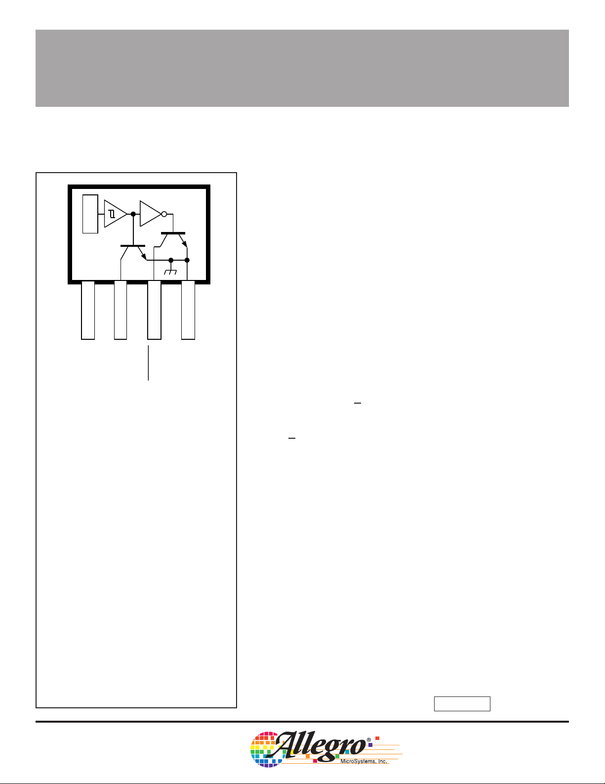
V
CC
1
SUPPLY
Pinning is shown viewed from branded side.
ABSOLUTE MAXIMUM RATINGS
at T
A
Supply Voltage, VCC. . . . . . . . . . . . . . . 14 V
Magnetic Flux Density, B . . . . . . Unlimited
Output OFF Voltage, VCE. . . . . . . . . . . 60 V
DISCONTINUED PRODUCT
Output ON Current, I
Continuous . . . . . . . . . . . . . . . . . 0.5 A
Peak (Start Up) . . . . . . . . . . . . . . 0.9 A
Operating Temperature Range,
TA . . . . . . . . . . . . . . . . . -20°C to +85°C
Storage Temperature Range,
TS . . . . . . . . . . . . . . . . -65°C to +150°C
Package Power Dissipation,
PD .. . . . . . . . . . . . . . . . . . . . . 750 mW
— FOR REFERENCE ONLY
32
OUTPUT
= +25°C
C
4
OUTPUT
Dwg. PH-002
GROUND
Each sensor IC includes a Hall-voltage generator, an operational
amplifier, a Schmitt trigger, a voltage regulator, and large-area dual
npn-output transistors. The regulator allows the IC to operate with
supply voltages ranging from 4.5 V to 14 V. On-chip compensation
circuitry stabilizes switch point performance over temperature. The
large bipolar junction output transistors are fed by a unique driver
stage, which minimizes power dissipation within the IC. The magnetic
operation of this device is similar to that of the UGN3275K complementary-output Hall-effect latch.
Output Q of the IC switches to the LOW state when the internal
Hall generator experiences a magnetic field that exceeds the rated
operate point. Output Q switches HIGH within one µs of the Output Q
change of state. When the device is exposed to a sufficient magnetic
field of opposite polarity, Output Q returns to the HIGH state, and
Output Q returns to the LOW state.
The UGN5275K is rated for operation over a temperature range of
-20°C to +85°C, and is supplied in an environmentally rugged, four-pin
miniature plastic SIP. Consult the factory for alternate packaging and
custom magnetic requirements.
FEATURES
■ High Sink-Current Capability
■ Magnetic Sensing, Complementary-Output Latch
■ On-Chip Schmitt Trigger Provides Hysteresis
■ Temperature-Compensated Switch Points
■ Rugged, Low-Profile SIP
Always order by complete part number: UGN5275K .
Page 2
5275
3
2
4
COMPLEMENTARY OUTPUT
POWERHALL® LATCH
ELECTRICAL CHARACTERISTICS at T
= +25°C, V
A
= 4.5 V to 14 V
CC
(unless otherwise noted).
Characteristic Symbol Test Conditions Min. Typ. Max. Units
Supply Voltage V
Output Saturation Voltage V
Output Leakage Current I
Supply Current l
Output Rise Time t
Output Fall Time t
Switch Time
Differential ∆tV
CC
CE(SAT)
CEX
CC
r
f
VCC = 14 V, IC = 300 mA — 400 600 mV
VCE = 14 V, VCC = 14 V — — 10 µA
VCC = 14 V, Output Open — 18 30 mA
VCC = 14 V, RL = 45 Ω, CL = 20 pF — 0.3 1.5 µs
VCC = 14 V, RL = 45 Ω,CL = 20 pF — 0.3 1.5 µs
= 14 V, RL = 45 Ω, CL = 20 pF — 1.0 3.0 µs
CC
4.5 — 14 V
MAGNETIC CHARACTERISTICS
TA = +25°CT
Characteristic Symbol Min. Max. Min. Max. Units
Operate Point B
Release Point B
Hysteresis B
OP
RP
hys
25 250 15 250 G
-250 -25 -250 -15 G
100 — 100 — G
= -20°C to +85°C
A
NOTE: As used here, negative flux densities are defined as less than zero (algebraic convention).
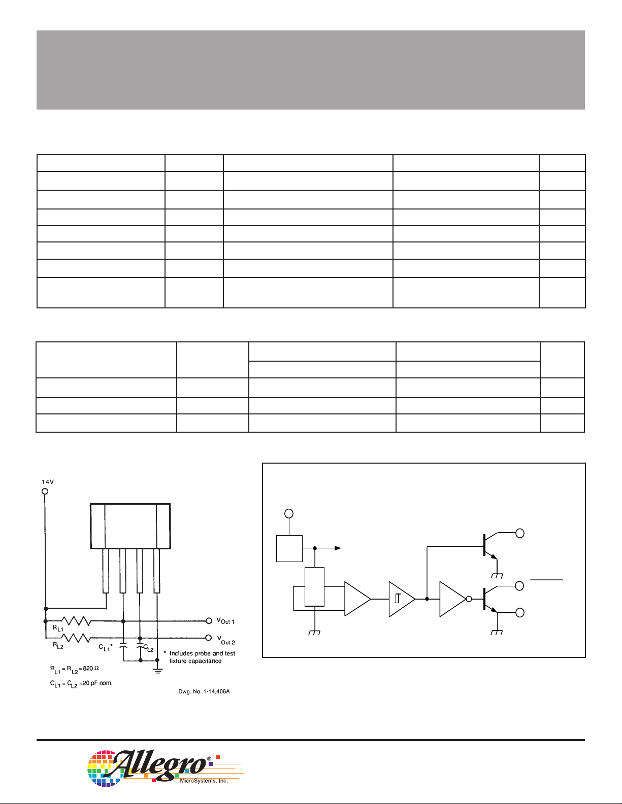
TEST CIRCUIT
FUNCTIONAL BLOCK DIAGRAM
V
1
CC
REG.
X
OUTPUT
OUTPUT
GROUND
Dwg. FH-002
115 Northeast Cutoff, Box 15036
Worcester, Massachusetts 01615-0036 (508) 853-5000
Copyright © 1988, 1995, Allegro MicroSystems, Inc.
Page 3

5275
COMPLEMENTARY OUTPUT
POWERHALL® LATCH
MOTOR COIL DRIVER
SWITCH POINTS VERSUS
TEMPERATURE
FIGURE 2
APPLICATIONS
The increased current sinking capability of the UGN5275K ideally
suits it for building small, inexpensive brushless dc motors using a
minimum number of external components. Figure 2 shows that the
only components required to commutate motor windings L1 and L2 are
the Hall effect IC, flyback diodes D1 and D2, and one decoupling
capacitor. The remaining components are optional for improving motor
performance. Care should be taken to ensure that the motor winding
impedances are high enough to guarantee that start-up surge currents
do not exceed the maximum rating of the Hall effect IC.
In the circuit shown, diodes D1 and D2 supply a flyback path for
the current of each winding to prevent reactive voltages from exceeding the sustained voltage rating of the Hall-effect IC output transistors.
Zener diode Z1 enables the windings to switch more rapidly by allowing the output voltage to rise above the source voltage, while simultaneously clamping the extreme reactive voltages.
The maximum output voltage level will be restricted to the following: VCC - VD3 + VZ + VD1 (blocking diode D3 voltage drop). Blocking
diode D3 provides reverse input-polarity protection, and should be
used only if reverse battery voltage is a possibility. Capacitor C1
decouples the Hall-effect IC from any high dv/dt transients injected
onto the VCC rail to prevent regulator latch-up within the device. Zener
diode Z2 and resistor R1 are required for operation from a VCC exceeding 14 V.
Page 4

5275
COMPLEMENTARY OUTPUT
POWERHALL® LATCH
HYSTERESIS CHARACTERISTICS
SENSOR LOCATION
ACTIVE AREA DEPTH
0.015"
0.38 mm
NOM
BRANDED
SURFACE
A
1 432
0.112"
2.86 mm
0.047"
1.19 mm
Dwg. MH-001-3A
GUIDE TO INSTALLATION
Dwg. No. A-12,062
1. All Hall Effect integrated circuits are susceptible to mechanical
stress effects. Caution should be exercised to minimize the
application of stress to the leads or the epoxy package. Use of
epoxy glue is recommended. Other types may deform the epoxy
package.
2. To prevent permanent damage to the Hall cell, heat-sink the leads
during hand-soldering. Recommended maximum conditions for
wave soldering are shown in the graph above.
115 Northeast Cutoff, Box 15036
Worcester, Massachusetts 01615-0036 (508) 853-5000
Page 5

5275
COMPLEMENTARY OUTPUT
POWERHALL® LATCH
45°
0.138
0.133
0.600
0.560
Dimensions in Inches
(controlling dimensions)
0.208
0.203
0.085
1234
MAX
0.063
0.059
0.033
0.015
45°
Dimensions in Millimeters
(for reference only)
5.28
5.16
45°
3.51
3.38
2.16
1234
MAX
15.24
14.23
1.60
1.50
45°
0.84
0.38
SEE NOTE
0.016
NOTES: 1. Tolerances on package height and width represent allowable mold offsets. Dimensions given are measured at the widest point (parting line).
2. Exact body and lead configuration at vendor’s option within limits shown.
3. Height does not include mold gate flash.
4. Recommended minimum PWB hole diameter to clear transition area is 0.035” (0.89 mm).
5. Where no tolerance is specified, dimension is nominal.
0.050
BSC
Dwg. MH-009C in
Allegro MicroSystems, Inc. reserves the right to make, from time to time, such departures from
the detail specifications as may be required to permit improvements in the design of its products.
The information included herein is believed to be accurate and reliable. However, Allegro
MicroSystems, Inc. assumes no responsibility for its use; nor for any infringements of patents or
other rights of third parties which may result from its use.
SEE NOTE
0.41
1.27
BSC
Dwg. MH-009C mm
Page 6

5275
COMPLEMENTARY OUTPUT
POWERHALL® LATCH
HALL-EFFECT SENSORS SELECTION GUIDE
Partial Part Avail. Oper. ␣ Operate Limits Over Temp.␣
Number Temp. B
3046 E/L +200 -200 15 Gear-Tooth Sensor
3054 K/S +300 +5 5.0 Unipolar Multiplex 1
3056 E/L +225 -225 15 Gear-Tooth Sensor
3058 E/L +300 -300 150 Gear-Tooth Sensor
3059 K/S +100 -100 20 AC Gear-Tooth Sensor
3060 K/S +35 -35 10 AC Gear-Tooth Sensor
3121 E/L +500 +80 60 Unipolar Switch
3122 E/L +430 +120 70 Unipolar Switch
3123 E/L +470 +160 70 Unipolar Switch
3132 K/L/S +95 -95 30 Bipolar Switch
3133 K/L/S +75 -75 30 Bipolar Switch
3134 E/L +50 -40 10 Bipolar Switch
3141 E/L +175 +10 20 Unipolar Switch
3142 E/L +245 +60 30 Unipolar Switch
3143 E/L +355 +150 30 Unipolar Switch
3144 E/L +450 +25 20 Unipolar Switch
3161 E +160 +30 5.0 2-Wire Unipolar Switch
3175 S +180 -180 80 Bipolar Latch
3177 S +150 -150 50 Bipolar Latch
3185 E/L +300 -300 280 Bipolar Latch
3187 E/L +175 -175 100 Bipolar Latch
3188 E/L +200 -200 160 Bipolar Latch
3189 E/L +250 -250 100 Bipolar Latch
3195 E/L +200 -200 110 Bipolar Latch 2, 3
3197 L +200 -200 110 Bipolar Latch 3
3235 S +200 +15 15 Unipolar Switch 4
3275 S +250 -250 100 Bipolar Latch 5
3421 E/L +300 -300 240 Direction Detection
3422 E/L +85 -85 10 Direction Detection
3503 S Typ. 1.3 mV/G – Linear Sensor
3515 E/L Typ. 5.0 mV/G – Chopper-Stabilized Linear Sensor
3516 E/L Typ. 2.5 mV/G – Chopper-Stabilized Linear Sensor
3517 L/S Typ. 5.0 mV/G – Chopper-Stabilized Linear Sensor
3518 L/S Typ. 2.5 mV/G – Chopper-Stabilized Linear Sensor
3625 S +150 -150 200* 900 mA Bipolar Latch 3, 5, 6
3626 S +150 -150 200* 400 mA Bipolar Latch 3, 5, 6
5140 E +240 +25 20 300 mA Unipolar Switch 3, 6
Operating Temperature Ranges:
C = 0°C to +70°C, S = -20°C to +85°C, E = -40°C to +85°C, K = -40°C to +125°C, L = -40°C to +150°C
Notes 1. Multiplexed two-wire sensor; after proper address, power/signal bus current indicates magnetic field condition.
2. Active pull down.
3. Protected.
4. Output 1 switches on south pole, output 2 switches on north pole for 2-phase, bifilar-wound, unipolar-driven brushless dc motor control.
5. Complementary outputs for 2-phase bifilar-wound, unipolar-driven brushless dc motor control.
6. Power driver output.
* Typical.
† Latches will not switch on removal of magnetic field; bipolar switches may switch on removal of field but require field reversal for reliable operation
over operating temperature range.
max B
OP
-200 -15 15 Unipolar Switch
min B
RP
min Function† Notes
hys
115 Northeast Cutoff, Box 15036
Worcester, Massachusetts 01615-0036 (508) 853-5000
 Loading...