

Page 1
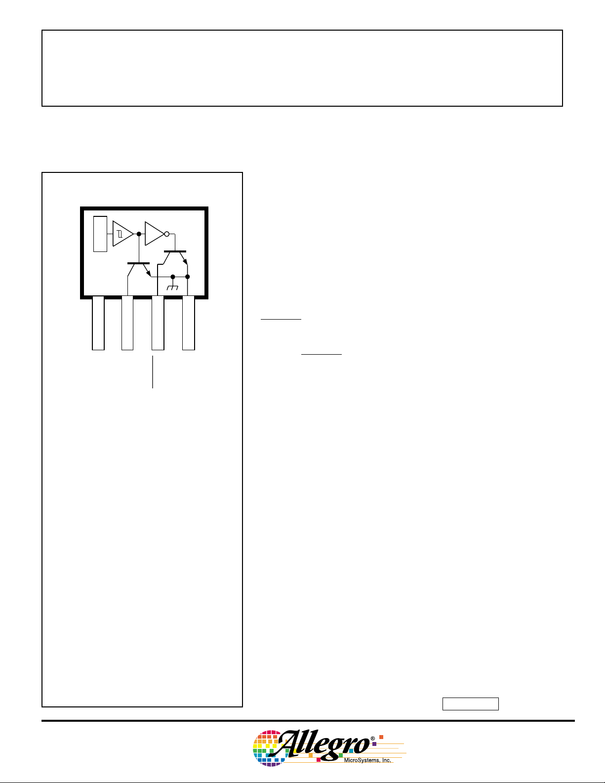
V
CC
1
X
SUPPLY
OUTPUT
32
OUTPUT
Dwg. PH-002
4
GROUND
Data Sheet
27632.2
3275
COMPLEMENTAR Y-OUTPUT
HALL-EFFECT LATCH
Type UGN3275K latching Hall-effect sensors are bipolar integrated circuits designed for electronic commutation of brushless dc
motors. They feature dual complementary outputs. The latches are
typically used to sense matched magnetic flux densities of alternating
polarity from multipole ring magnets.
Each sensor IC includes a Hall voltage generator, operational
amplifier, Schmitt trigger, voltage regulator, and dual bipolar output
transistors. The regulator allows use of the integrated circuit with
supply voltages of 4.5 V to 24 V.
If the Hall cell is exposed to a magnetic flux density greater than
the operate threshold (BOP), OUTPUT goes low (turns on) and
OUTPUT goes high (turns off). The outputs will hold (latch) this state
until magnetic field reversal exposes the Hall cell to a magnetic flux
density below the release threshold (BRP) when OUTPUT will go high
(off) and OUTPUT will go low (on). This state is also latched. Under
any condition one output is on while the other is off. Because the
operating state switches only with magnetic field reversal, and not
merely with a change in the strength, these integrated circuits qualify
as true Hall-effect latches.
Pinning is shown viewed from branded side.
ABSOLUTE MAXIMUM RATINGS
Power Supply, VCC. . . . . . . . . . . . . . . . 25 V
Magnetic Flux Density, B . . . . . . Unlimited
Output OFF Voltage, V
Output ON Current, I
Operating Temperature Range,
TA . . . . . . . . . . . . . . . . . -20°C to +85°C
Storage Temperature Range,
TS . . . . . . . . . . . . . . . . -65°C to +150°C
. . . . . . . . . . 25 V
OUT
. . . . . . . . . . 50 mA
OUT
These complementary-output Hall-effect latches are supplied in a
four-pin plastic SIP, 0.200" (5.08 mm) wide, 0.130" (3.3 mm) high, and
0.060" (1.54 mm) thick.
FEATURES
■ Operable with Multipole Ring Magnets
■ High Reliability
■ Small Size
■ Output Compatible with All Digital Logic Families
■ 4.5 V to 24 V Operation
■ High Hysteresis Level Minimizes Stray-Field Problems
■ Complementary Outputs
Always order by complete part number: UGN3275K .
Page 2
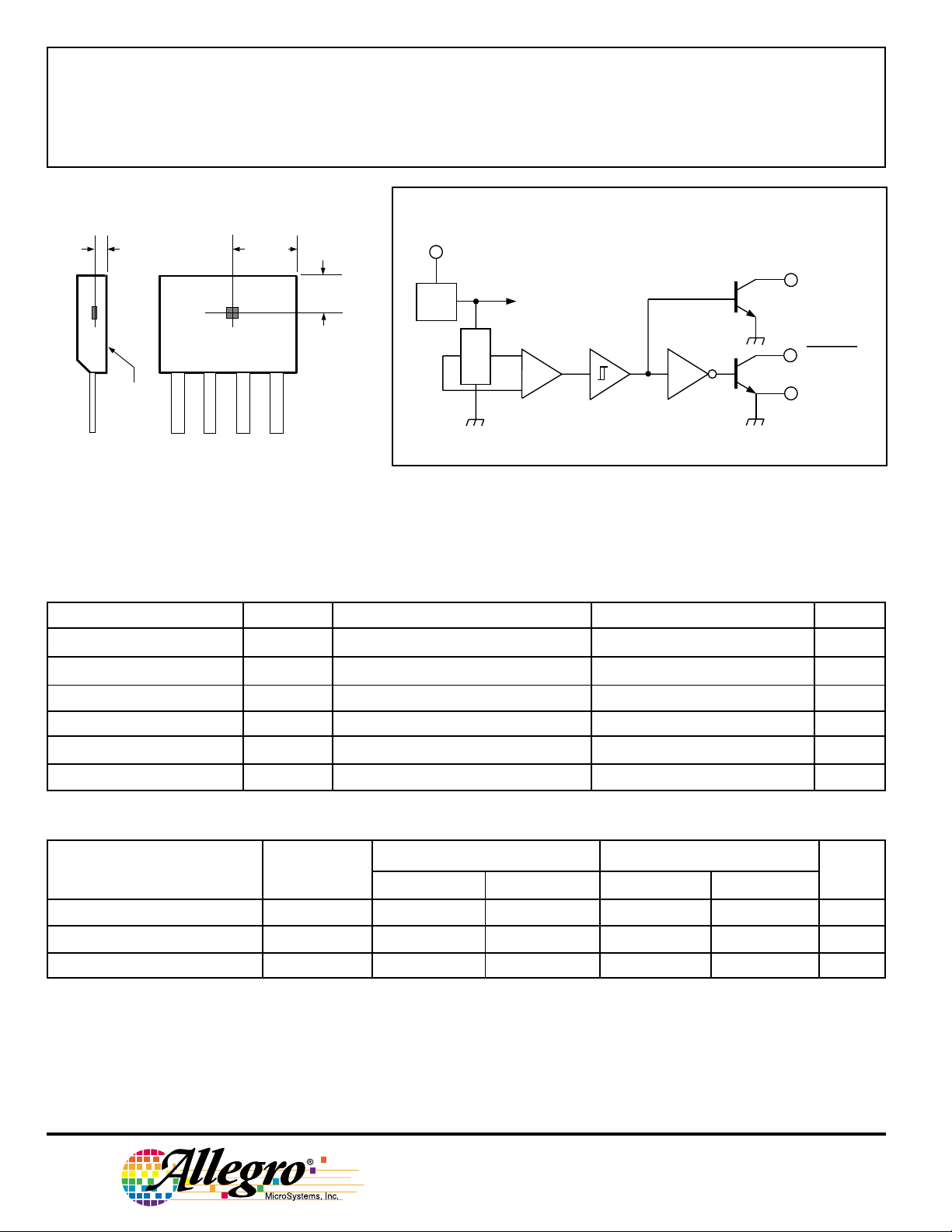
3275
COMPLEMENTARY-OUTPUT
HALL-EFFECT LATCH
SENSOR LOCATION
ACTIVE AREA DEPTH
0.015"
0.38 mm
NOM
0.096"
2.44 mm
0.047"
1.21 mm
A
1
REG.
FUNCTIONAL BLOCK DIAGRAM
V
CC
X
2
OUTPUT
3
OUTPUT
BRANDED
SURFACE
1 432
Dwg. MH-001-2A
ELECTRICAL CHARACTERISTICS at T
= +25°C, V
A
= 4.5 V to 24 V
CC
4
GROUND
Dwg. FH-002
(unless otherwise noted).
Characteristic Symbol Test Conditions Min. Typ. Max. Units
Supply Voltage V
Output Saturation Voltage V
OUT(SAT)
Output Leakage Current I
Supply Current l
Output Rise Time t
Output Fall Time t
CC
OFF
CC
r
f
Operating 4.5 — 24 V
VCC = 4.5 V, I
V
= 24 V, VCC = 24 V, B < B
OUT
VCC = 24 V, B < B
= 20 mA, B > B
OUT
RP
RP
OP
— — 400 mV
——10µA
— — 7.0 mA
VCC = 12 V, RL = 820 Ω, CL = 20 pF — 0.04 0.4 µs
VCC = 12 V, RL = 820 Ω, CL = 20 pF — 0.18 0.4 µs
MAGNETIC CHARACTERISTICS
TA = +25°CT
= -20°C to +85°C
A
Characteristic Symbol Min. Max. Min. Max. Units
Operate Point B
Release Point B
Hysteresis B
OP
RP
hys
25 250 15 250 G
-250 -25 -250 -15 G
100 — 100 — G
NOTE: As used here, negative flux densities are defined as less than zero (algebraic convention).
115 Northeast Cutoff, Box 15036
Worcester, Massachusetts 01615-0036 (508) 853-5000
Copyright © 1991, 2000 Allegro MicroSystems, Inc.
Page 3

3275
COMPLEMENTARY-OUTPUT
HALL-EFFECT LATCH
SEE NOTE
Dimensions in Inches
(controlling dimensions)
0.208
0.203
45°
0.138
0.133
0.085
1234
MAX
0.600
0.560
0.063
0.059
0.033
0.0173
0.0138
45°
SEE NOTE
Dimensions in Millimeters
(for reference only)
5.28
5.16
45°
3.51
3.38
2.16
1234
MAX
15.24
14.23
1.60
1.50
45°
0.84
0.44
0.35
0.0189
0.0142
0.050
BSC
Dwg. MH-009D in
0.48
0.36
1.27
BSC
Dwg. MH-009D mm
NOTES: 1. Tolerances on package height and width represent allowable mold offsets.
Dimensions given are measured at the widest point (parting line).
2. Exact body and lead configuration at vendor’s option within limits shown.
3. Height does not include mold gate flash.
4. Recommended minimum PWB hole diameter to clear transition area is 0.035” (0.89 mm).
5. Where no tolerance is specified, dimension is nominal.
The products described herein are manufactured under one or more of the following U.S. patents: 5,045,920; 5,264,783; 5,442,283;
5,389,889; 5,581,179; 5,517,112; 5,619,137; 5,621,319; 5,650,719; 5,686,894; 5,694,038; 5,729,130; 5,917,320; and other patents pending.
Allegro MicroSystems, Inc. reserves the right to make, from time to time, such departures from the detail specifications as may be required to
permit improvements in the performance, reliability, or manufacturability of its products. Before placing an order, the user is cautioned to verify
that the information being relied upon is current.
Allegro products are not authorized for use as critical components in life-support appliances, devices, or systems without express written
approval.
The information included herein is believed to be accurate and reliable. However, Allegro MicroSystems, Inc. assumes no responsibility for its
use; nor for any infringements of patents or other rights of third parties that may result from its use.
Page 4

3275
COMPLEMENTARY-OUTPUT
HALL-EFFECT LATCH
HALL-EFFECT SENSORS
Partial Part Avail. Oper. Characteristics at T
Number Temp. B
HALL-EFFECT UNIPOLAR SWITCHES in order of B
3240 E/L +50 +5.0 10 chopper stabilized 1
3210 E ±60 ±5.0 7.7 micropower, chopper stabilized
3361 E +55* +110‡ 5.0* 2-wire, chopper stabilized
3362 E +110 +55 5.0* 2-wire, chopper stabilized
3161 E +160 +30 20 2-wire
3141 E/L +160 +10 55
3235 S +175 +25 15* output 1 2
5140 E +200 +50 55 300 mA output 1, 3
3142 E/L +230 +75 55
3143 E/L +340 +165 55
3144 E/L +350 +50 55
3122 E/L +400 +140 105
3123 E/L +440 +180 105
3121 E/L +450 +125 105
3150 J +40 to +850 – 20
HALL-EFFECT LATCHES & BIPOLAR SWITCHES† in order of B
3260 E/L +30 -30 20 bipolar, chopper stabilized
3280 E/L +40 -40 45 chopper stabilized
3134 E/L +50 -50 27 bipolar switch
3133 K/L/S +75 -75 52 bipolar switch
3281 E/L +90 -90 100 chopper stabilized
3132 K/L/S +95 -95 52 bipolar switch
3187 E/L +150 -150 100*
3177 S +150 -150 200
3625 S +150 -150 200 900 mA outputs 1, 3, 5
3626 S +150 -150 200 400 mA outputs 1, 3, 5
3195 E/L +160 -160 220 1, 4
3197 L +160 -160 230 1
3175 S +170 -170 200
3188 E/L +180 -180 200*
3283 E/L +180 -180 300 chopper stabilized
3189 E/L +230 -230 100*
3275 S +250 -250 100* 5
3185 E/L +270 -270 340*
Operating Temperature Ranges:
S = -20°C to +85°C, E = -40°C to +85°C, J = -40°C to +115°C, K = -40°C to +125°C, L = -40°C to +150°C
Notes 1. Protected.
2. Output 1 switches on south pole, output 2 switches on north pole for 2-phase, bifilar-wound, unipolar-driven brushless dc
motor control.
3. Power driver output.
4. Active pull down.
5. Complementary outputs for 2-phase bifilar-wound, unipolar-driven brushless dc motor control.
* Minimum. ‡ Maximum
† Latches will not switch on removal of magnetic field; bipolar switches may switch on removal of field but require field reversal
for reliable operation over operating temperature range.
OP(max)
-25 -175 15* output 2 2
B
RP(min)
= +25°C
A
B
hys(typ)
Features Notes
and B
OP
programmable, chopper stabilized
OP
hys
and B
1
hys
115 Northeast Cutoff, Box 15036
Worcester, Massachusetts 01615-0036 (508) 853-5000
 Loading...