

Page 1
3235
DUAL-OUTPUT
HALL-EFFECT SWITCH
X
V
CC
1
SUPPLY
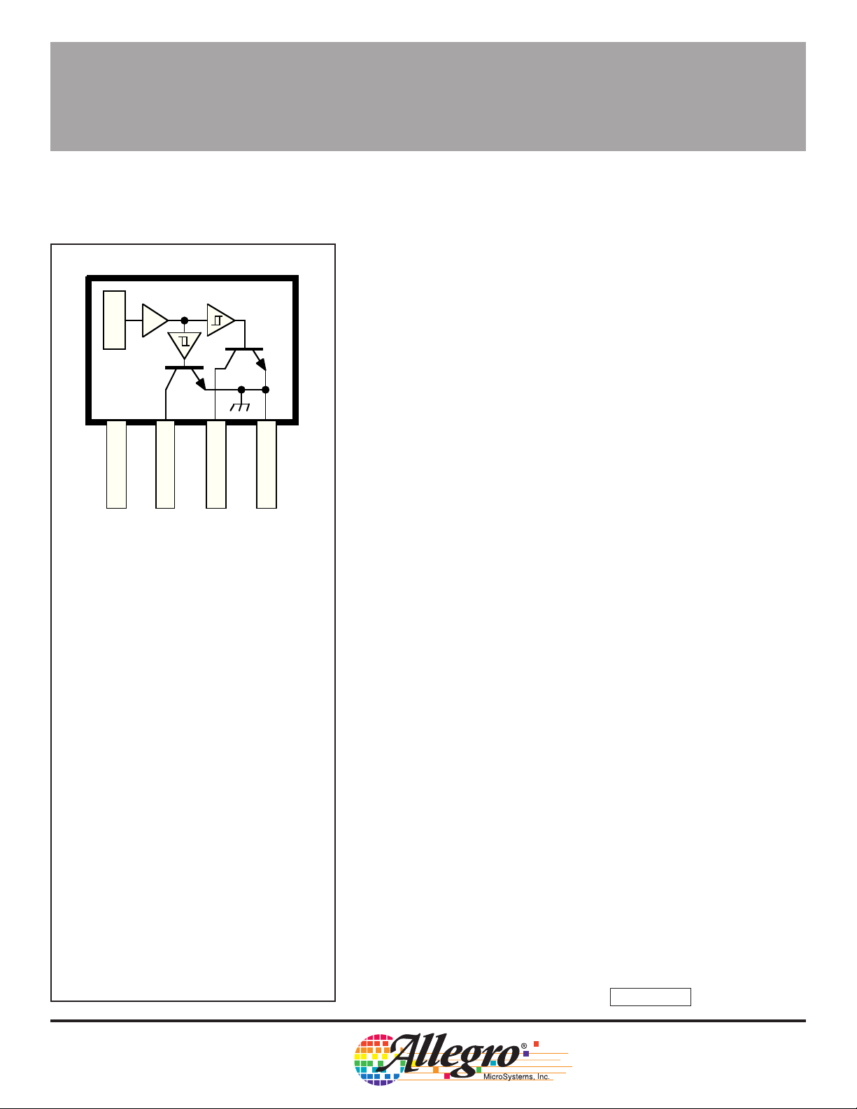
Pinning is shown viewed from branded side.
32
1
OUTPUT
4
2
OUTPUT
Dwg. PH-007
GROUND
Data Sheet
27633A*
3235
DUAL-OUTPUT
HALL-EFFECT SWITCH
Type UGN3235K Hall-effect sensors are bipolar integrated circuits
designed for commutation of brushless dc motors, and other rotary
encoding applications using multi-pole ring magnets. The device
features two outputs which are independently activated by magnetic
fields of opposite polarity.
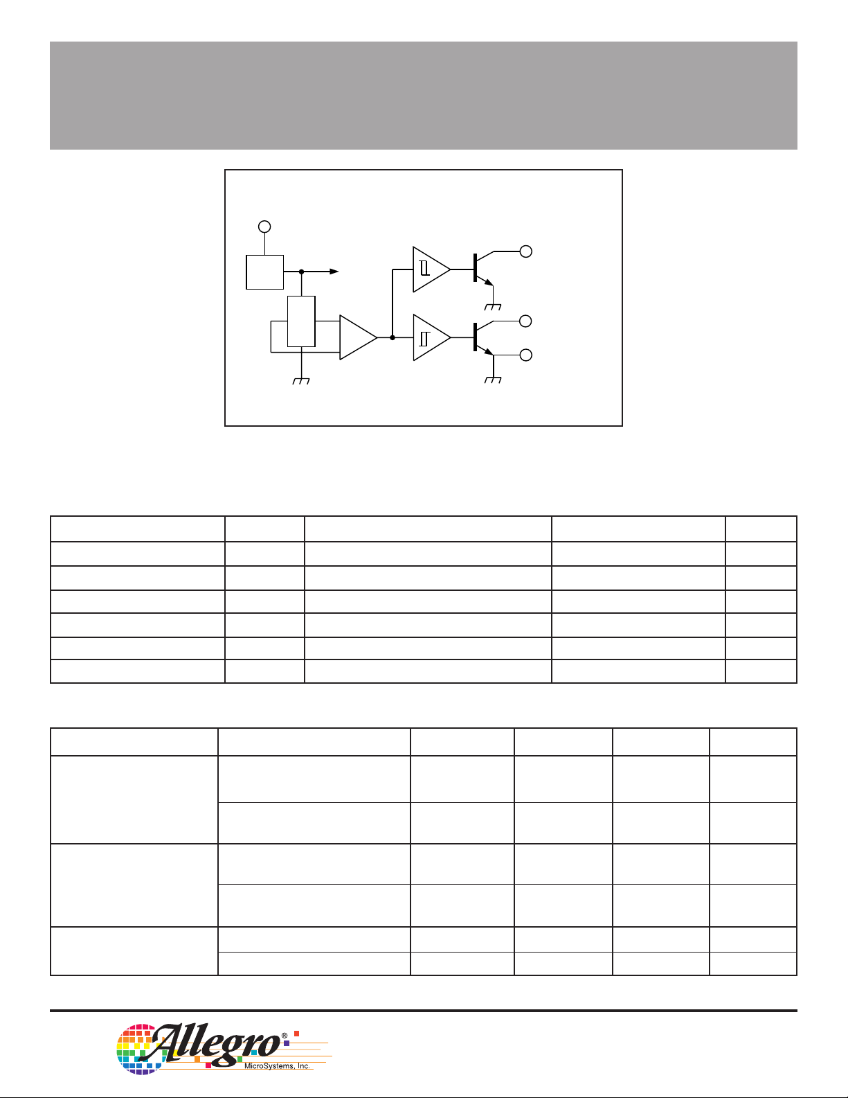
Each sensor IC includes a Hall voltage generator, two Schmitt
triggers, a voltage regulator, output transistors, and on-board reverse
polarity protection. The regulator enables these devices to operate
from voltages ranging between 4.5 V and 24 V. On-chip compensation
circuitry stabilizes the switch points over temperature.
Each open-collector output is independently operated by the
proper amount and polarity of incident magnetic flux. Output 1 responds only to the positive flux from the south pole of a magnet,
Output 2 to the negative flux from the north pole of a magnet. When
the sensor experiences the field of a south magnetic pole greater than
the maximum operate point of Output 1, that output switches to the
LOW state and Output 2 is unaffected. When the incident flux falls
below the minimum release point for Output 1, that output returns to
the HIGH state and Output 2 remains unchanged.
Output 2 independently responds in the same manner to the
negative flux from the north magnetic pole of a magnet. Figure 1
shows a zone in the region of 0 G, tH, where both outputs are in the
HIGH or OFF state. This constitutes a delay that is independent of
rate of change of the incident magnetic field and ensures that both
outputs are never ON simultaneously. This is an essential feature for
driving brushless dc motors with a minimum of reactive transient
currents.
ABSOLUTE MAXIMUM RATINGS
at T
= +25°C
A
Power Supply, VCC. . . . . . . . . . . . . . . . 25 V
Reverse Battery Voltage, V
Magnetic Flux Density, B . . . . . . Unlimited
Output OFF Voltage, V
Output ON Current, I
Operating Temperature Range,
TA. . . . . . . . . . . . . . . . -20°C to + 85°C
Storage Temperature Range
TS. . . . . . . . . . . . . . . . -65°C to +150°C
OUT
OUT
. . . . . -30 V
RCC
. . . . . . . . . . 25 V
. . . . . . . . . . 50 mA
The UGN3235K is supplied in a four-pin plastic single in-line
package (SIP).
FEATURES
■ Reliable and Rugged Magnetic Sensing Switch
■ Two Outputs Independently Switched by North and South Poles
■ Independent Actuation of Outputs Minimizes Inductive-Load
Reactive Transient
■ Built-in Hysteresis Minimizes Interference from Stray Fields
■ Operates from 4.5 V to 24 V
■ Outputs Compatible with All Logic Levels
■ On-Board Reverse Polarity Protection
■ Open-Collector, Active-Low Outputs
Always order by complete part number: UGN3235K .
Page 2
3235
3
1
2
4
DUAL-OUTPUT
HALL-EFFECT SWITCH
V
CC
REG.
FUNCTIONAL BLOCK DIAGRAM
OUTPUT
1
X
ELECTRICAL CHARACTERISTICS at T
= +25°C (unless otherwise noted).
A
OUTPUT
GROUND
Dwg. FH-003A
2
Characteristic Symbol Test Conditions Min. Typ. Max. Units
Supply Voltage V
Output Saturation Voltage V
OUT(SAT)
Output Leakage Current I
Supply Current I
Output Rise Time t
Output Fall Time t
CC
OFF
CC
VCC = 24 V, I
V
= 24 V, VCC = 24 V — — 1.0 µA
OUT
= 20 mA — 160 400 mV
OUT
VCC = 24 V, Output Open — 6.0 8.0 mA
r
f
VCC = 14 V, RL = 820 Ω, CL = 20 pF — 0.04 0.4 µs
VCC = 14 V, RL = 820 Ω, CL = 20 pF — 0.18 0.4 µs
4.5 — 24 V
MAGNETIC CHARACTERISTICS at VCC = 4.5 V to 24 V
Characteristic Test Conditions Output Min. Max. Units
Operate Point, B
OP
TA = +25°C Q1 50 175 G
Q2 -175 -50 G
T
= -20°C to +85°C Q1 35 200 G
A
Q2 -200 -35 G
Release Point, B
RP
TA = +25°C Q1 25 160 G
Q2 -160 -25 G
T
= -20°C to +85°C Q1 15 190 G
A
Q2 -190 -15 G
Hysteresis, B
hys
TA = +25°C Q1 & Q2 15 100 G
= -20°C to +85°C Q1 & Q2 15 110 G
T
A
115 Northeast Cutoff, Box 15036
Worcester, Massachusetts 01615-0036 (508) 853-5000
W
Copyright © 1989, 1995 Allegro MicroSystems, Inc.
Page 3
3235
OUTPUT VOLTAGE
DUAL-OUTPUT
HALL-EFFECT SWITCH
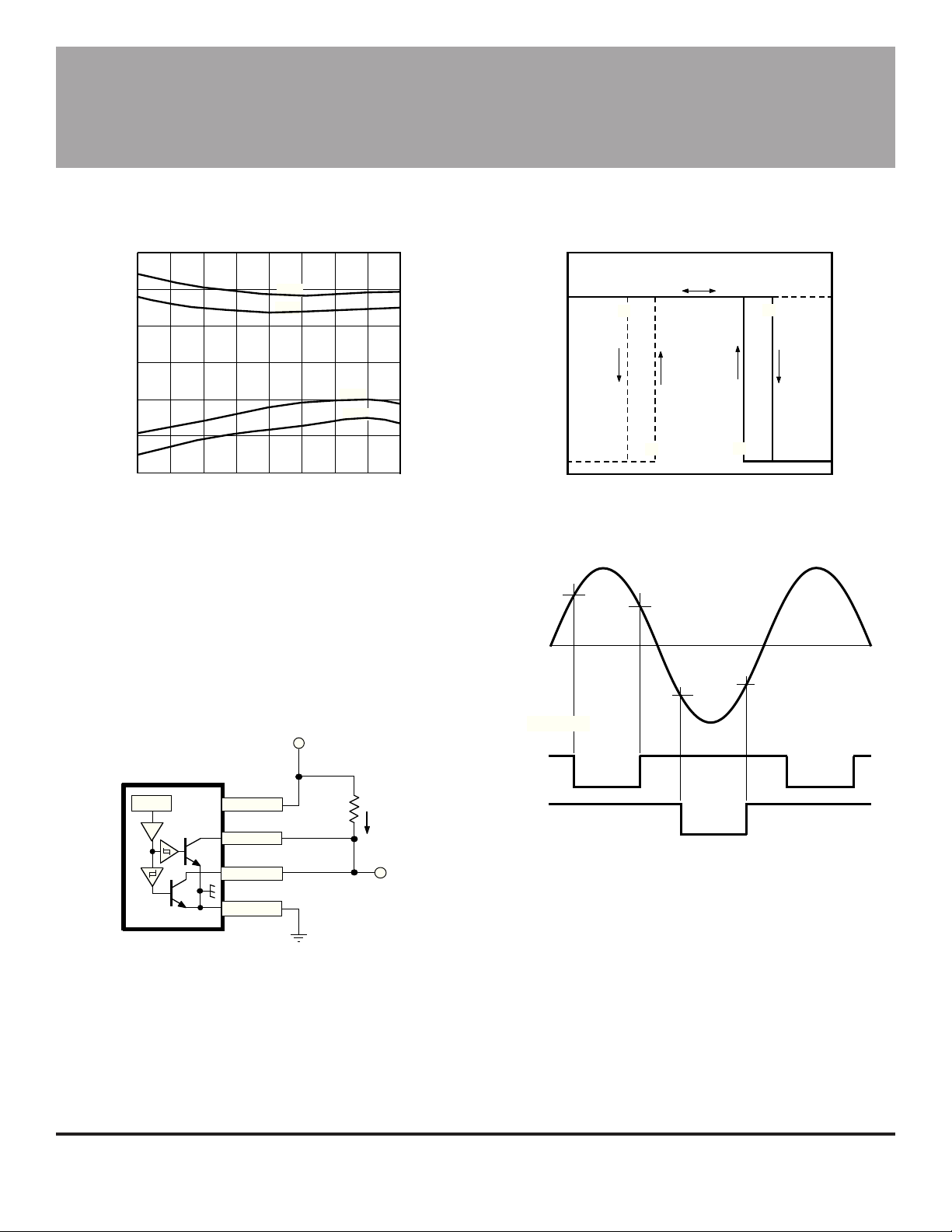
SWITCH POINTS vs. TEMPERATURE
150
B
100
50
0
-50
SWITCH POINT IN GAUSS
-100
-150
-25 25 75 125
-50
0 50 100
AMBIENT TEMPERATURE IN °C
OPS
B
RPS
B
RPN
B
OPN
150
Dwg. GH-027-1
APPLICATIONS
Figure 1 illustrates a method of sensing the presence
of either a north or south magnetic pole. Because the
UGN3235K is an open-collector device, it is possible to
directly connect (wired OR) the two outputs. This causes
the output to go LOW when either a north pole or south
pole of sufficient magnitude is sensed. The device
connected in this manner suits many applications, ranging
from doubling the resolution of a ring-magnet encoder, to
zero-crossing detection.
V
CC
4.5 V to 24 V
CC
X
V
143
2
20 mA
SIGNAL
OUTPUT
TRANSFER CHARACTERISTICS
V
OUT(OFF)
25 V
MAX
0
-B
+B (SOUTH)
B
OP1
0
MAGNETIC FLUX
–B (NORTH)
Q1
Q2
OUTPUTS
B
OP2
B
RP2
0
MAGNETIC FLUX
B
RP1
B
RP2
OFF
ON
ON
OFF
B
OP2
DEAD
TIME
FIGURE 2
ZERO-CROSSING DETECTION
B
OP1
B
RP1
V
OUT(SAT)
+B
Dwg. GH-043A
DEAD
TIME
ON
OFF
Dwg. WH-009-1
FIGURE 1
BIPOLAR DETECTOR
Figure 2 shows that there is a “dead time” approximately centered around 0 G. Thus, by sensing the HIGH
portion of the UGN3235K wired-OR output, the zerocrossing can be detected.
Dwg. EH-010
Figure 3 shows that the UGN3235K makes it possible
to implement a very efficient brushless dc motor control
using a minimum number of components. Referring again
to Figure 1, the dead time (where both drivers are OFF)
allows the motor coil field to decay sufficiently. This
avoids both excessive reactive voltages and the magnetic
drag resulting from the motor coils working in opposition
to each other.
Page 4

3235
A
DUAL-OUTPUT
HALL-EFFECT SWITCH
0.1 µF 5 V to 24 V
X
V
CC
CC
V
1
2
1 kΩ
1 kΩ
2N4356
SENSOR LOCATION
(±0.005” [0.13mm] die placement)
ACTIVE AREA DEPTH
0.015"
0.38 mm
NOM
0.106"
2.70 mm
0.058"
1.47 mm
3
4
FIGURE 3
MOTOR DRIVER
280
260
240
220
TEMPERATURE IN °C
2N4356
Dwg. EH-009
GUIDE TO INSTALLATION
200
BRANDED
SURFACE
1 432
Dwg. MH-001-1B
0
515
TIME IN SECONDS
10 20
Dwg. GA-001
All Hall effect integrated circuits are susceptible to mechanical stress effects. Caution
should be exercised to minimize the application of stress to the leads or the epoxy
package. Use of epoxy glue is recommended. Other types may deform the epoxy
package.
To prevent permanent damage to the Hall cell, heat-sink the leads during hand
soldering. Recommended maximum conditions for wave soldering are shown in the
graph above.
115 Northeast Cutoff, Box 15036
Worcester, Massachusetts 01615-0036 (508) 853-5000
Page 5

3235
DUAL-OUTPUT
HALL-EFFECT SWITCH
Dimensions in Inches
(controlling dimensions)
0.208
0.203
45°
0.138
0.133
0.085
1234
MAX
0.600
0.560
0.063
0.059
0.033
0.015
45°
Dimensions in Millimeters
(for reference only)
5.28
5.16
45°
3.51
3.38
2.16
1234
MAX
15.24
14.23
1.60
1.50
45°
0.84
0.38
SEE NOTE
0.016
NOTES: 1. Tolerances on package height and width represent allowable mold offsets. Dimensions given are measured at the widest point (parting line).
2. Exact body and lead configuration at vendor’s option within limits shown.
3. Height does not include mold gate flash.
4. Recommended minimum PWB hole diameter to clear transition area is 0.035” (0.89 mm).
5. Where no tolerance is specified, dimension is nominal.
0.050
BSC
Dwg. MH-009C in
Allegro MicroSystems, Inc. reserves the right to make, from time to time, such departures from
the detail specifications as may be required to permit improvements in the design of its products.
Components made under military approvals will be in accordance with the approval requirements.
The information included herein is believed to be accurate and reliable. However, Allegro
MicroSystems, Inc. assumes no responsibility for its use; nor for any infringements of patents or
other rights of third parties which may result from its use.
SEE NOTE
0.41
1.27
BSC
Dwg. MH-009C mm
Page 6

3235
DUAL-OUTPUT
HALL-EFFECT SWITCH
This page intentionally left blank
115 Northeast Cutoff, Box 15036
Worcester, Massachusetts 01615-0036 (508) 853-5000
Page 7

3235
DUAL-OUTPUT
HALL-EFFECT SWITCH
This page intentionally left blank
Page 8

3235
DUAL-OUTPUT
HALL-EFFECT SWITCH
HALL-EFFECT SENSORS SELECTION GUIDE
Partial Part Avail. Oper. ␣ Operate Limits Over Temp.␣
Number Temp. B
3046 E/L +200 -200 15 Gear-Tooth Sensor
3054 K/S +300 +5 5.0 Unipolar Multiplex 1
3056 E/L +225 -225 15 Gear-Tooth Sensor
3058 E/L +300 -300 150 Gear-Tooth Sensor
3059 K/S +100 -100 20 AC Gear-Tooth Sensor
3060 K/S +35 -35 10 AC Gear-Tooth Sensor
3121 E/L +500 +80 60 Unipolar Switch
3122 E/L +430 +120 70 Unipolar Switch
3123 E/L +470 +160 70 Unipolar Switch
3132 K/L/S +95 -95 30 Bipolar Switch
3133 K/L/S +75 -75 30 Bipolar Switch
3134 E/L +50 -40 10 Bipolar Switch
3141 E/L +175 +10 20 Unipolar Switch
3142 E/L +245 +60 30 Unipolar Switch
3143 E/L +355 +150 30 Unipolar Switch
3144 E/L +450 +25 20 Unipolar Switch
3161 E +160 +30 5.0 2-Wire Unipolar Switch
3175 S +180 -180 80 Bipolar Latch
3177 S +150 -150 50 Bipolar Latch
3185 E/L +300 -300 280 Bipolar Latch
3187 E/L +175 -175 100 Bipolar Latch
3188 E/L +200 -200 160 Bipolar Latch
3189 E/L +250 -250 100 Bipolar Latch
3195 E/L +200 -200 110 Bipolar Latch 2, 3
3197 L +200 -200 110 Bipolar Latch 3
3235 S +200 +15 15 Unipolar Switch 4
3275 S +250 -250 100 Bipolar Latch 5
3421 E/L +300 -300 240 Direction Detection
3422 E/L +85 -85 10 Direction Detection
3503 S Typ. 1.3 mV/G – Linear Sensor
3515 E/L Typ. 5.0 mV/G – Chopper-Stabilized Linear Sensor
3516 E/L Typ. 2.5 mV/G – Chopper-Stabilized Linear Sensor
3517 L/S Typ. 5.0 mV/G – Chopper-Stabilized Linear Sensor
3518 L/S Typ. 2.5 mV/G – Chopper-Stabilized Linear Sensor
3625 S +150 -150 200* 900 mA Bipolar Latch 3, 5, 6
3626 S +150 -150 200* 400 mA Bipolar Latch 3, 5, 6
5140 E +240 +25 20 300 mA Unipolar Switch 3, 6
Operating Temperature Ranges:
C = 0°C to +70°C, S = -20°C to +85°C, E = -40°C to +85°C, K = -40°C to +125°C, L = -40°C to +150°C
Notes 1. Multiplexed two-wire sensor; after proper address, power/signal bus current indicates magnetic field condition.
2. Active pull down.
3. Protected.
4. Output 1 switches on south pole, output 2 switches on north pole for 2-phase, bifilar-wound, unipolar-driven brushless dc motor control.
5. Complementary outputs for 2-phase bifilar-wound, unipolar-driven brushless dc motor control.
6. Power driver output.
* Typical.
† Latches will not switch on removal of magnetic field; bipolar switches may switch on removal of field but require field reversal for reliable operation
over operating temperature range.
max B
OP
-200 -15 15 Unipolar Switch
RP
min B
min Function† Notes
hys
115 Northeast Cutoff, Box 15036
Worcester, Massachusetts 01615-0036 (508) 853-5000
 Loading...