

Page 1
Evaluation Board User Guide
UG-435
10844-001
One Technology Way • P. O. Box 9106 • Norwood, MA 02062-9106, U.S.A. • Tel: 781.329.4700 • Fax: 781.461.3113 • www.analog.com
Evaluation Board for the ADF4351 Fractional-N PLL Frequency Synthesizer
FEATURES
Self-contained board including PLL, VCO, loop filter (35 kHz),
25 MHz TCXO reference, USB interface, and voltage
regulators
Accompanying software allows control of synthesizer
functions from a PC
Choice of power supply via USB or external feeding
Typical phase noise performance of −104 dBc/Hz @ 3 kHz
offset from carrier (1 GHz output frequency)
EVALUATION KIT CONTENTS
EVAL-ADF4351EB1Z board
USB Standard-A to Mini-B cable
CD that includes
Self-installing software that allows users to control the
board and exercise all functions of the device
Electronic version of the ADF4351 data sheet
Electronic version of the UG-435 user guide
ADDITIONAL EQUIPMENT
PC running Windows XP or more recent version
Spectrum analyzer
Oscilloscope (optional)
DOCUMENTS NEEDED
ADF4351 data sheet
REQUIRED SOFTWARE
Analog Devices ADF435xPLL software (Version 4 or higher)
ADIsimPLL™
GENERAL DESCRIPTION
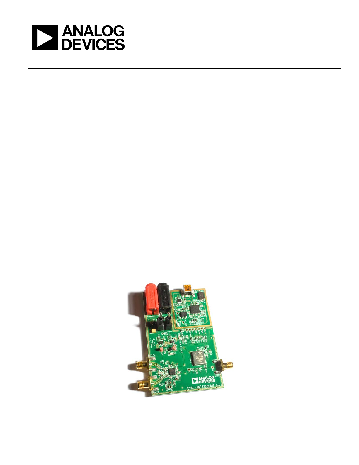
This board is designed to allow the user to evaluate the performance of the ADF4351 frequency synthesizer for phase-locked
loops (PLLs). Figure 1 shows the board, which contains the
ADF4351 integrated synthesizer and VCO, SMA connectors for
the output signal, power supplies, a reference oscillator, and an
USB connector. There is also a loop filter (35 kHz) on board.
The evaluation board is set up for a 25 MHz PFD comparison
frequency. An on-board TCXO provides the 25 MHz reference
frequency.
The package also contains Windows® software (XP or later) to
allow easy programming of the synthesizer.
PLEASE SEE THE LAST PAGE FOR AN IMPORTANT
WARNING AND LEGAL TERMS AND CONDITIONS.
EVALUATION BOARD
Figure 1. EVAL-ADF4351EB1Z
Rev. 0 | Page 1 of 20
Page 2

UG-435 Evaluation Board User Guide
TABLE OF CONTENTS
Features .............................................................................................. 1
Evaluation Kit Contents ................................................................... 1
Additional Equipment ..................................................................... 1
Documents Needed .......................................................................... 1
Required Software ............................................................................ 1
General Description ......................................................................... 1
Evaluation Board .............................................................................. 1
Revision History ............................................................................... 2
Quick Start Guide ............................................................................. 3
Evaluation Board Hardware ............................................................ 4
Power Supplies .............................................................................. 4
REVISION HISTORY
6/12—Revision 0: Initial Version
Input Signals...................................................................................4
Loop Filter ......................................................................................4
Output Signals ...............................................................................4
Evaluation Board Setup Procedure .................................................5
Software Installation .....................................................................5
Evaluation Board Software ...............................................................9
Evaluation and Test ........................................................................ 11
Evaluation Board Schematics and Artwork ................................ 12
Ordering Information .................................................................... 17
Bill of Materials ........................................................................... 17
Rev. 0 | Page 2 of 20
Page 3

Evaluation Board User Guide UG-435
QUICK START GUIDE
Follow these steps to quickly evaluate the ADF4351 device:
1. Install the ADF435x software from the CD.
2. Connect the EVAL-ADF4351EB1Z to the PC and install
the necessary drivers.
3. Follow the hardware driver installation procedure.
4. Ensure that Switches SW1 and SW2 are closed.
5. Run the ADF435x software.
6. Select the USB board connection and the ADF4351 device
in the Select Device and Connection tab of the software
front panel window.
7. Click the Main Controls tab. Update all registers.
8. Connect the spectrum analyzer to J2.
9. Measure the results.
Rev. 0 | Page 3 of 20
Page 4
UG-435 Evaluation Board User Guide
10844-002
10844-003
EVALUATION BOARD HARDWARE
The EVAL-ADF4351EB1Z schematics are shown in Figure 22
to Figure 24.
POWER SUPPLIES
The EVAL-ADF4351EB1Z can be powered either from the USB
port or via dc power connectors (4 mm banana connectors).
When feeding via banana connectors, 3.75 V to 5.5 V is a
suitable feeding voltage. The power supply circuitry allows
the user to use one or two separate LDOs to feed the ADF4351
(using fewer LDOs increases the risk of spur contaminated dc
feeds). Consult the board schematic in Figure 22, Figure 23,
and Figure 24 to determine a suitable setting.
An LED, D6, indicates when USB power is available, and
another LED, D5, indicates when the ADF4351 is powered.
Switch S1 is used to power the ADF4351 from the external
dc connectors USB port and Switch S2 to power from the
USB port.
In case the USB processor or clock causes spurs on the RF
output signal, the user may feed the evaluation board via the
dc connectors and unplug the USB cable, thereby removing
power from the USB interface circuitry. There is also a
grounded frame surrounding the USB interface circuitry
to allow mounting of a shielding box.
INPUT SIGNALS
The 25 MHz TCXO from Rakon provides the necessary reference
signal. An external REFIN may be used if desired. In this case,
disable the on-board TCXO by removing L10 and R59. R9 can
be populated with 50 Ω to adjust impedance matching of the
evaluation board to the external reference source.
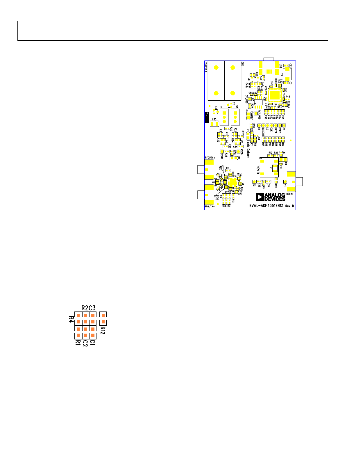
LOOP FILTER
The loop filter schematic is included in the board schematic on
Figure 22. The loop filter component placements are clarified in
Figure 2.
Figure 3. Evaluation Board Silkscreen
OUTPUT SIGNALS
The EVAL-ADF4351EB1Z has two SMA output connectors
(differential outputs). The device is quite sensitive to impedance
unbalance. If only one port of a differential pair is used,
terminate the other with a 50 Ω load.
The board contains 7.5 nH shunt inductors on the RF output
stages, which is optimum for a frequency range of 1 GHz to
4.4 GHz. Lower frequencies than this require larger output
stage inductors, or a 50 Ω resistor to V
output power, but wider frequency bandwidth than the
inductors. Consult the ADF4351 data sheet for more
information.
The MUXOUT signal can be monitored at the test point labeled
MUXOUT.
, which provides lower
DD
Figure 2. Loop Filter Placement
Rev. 0 | Page 4 of 20
Page 5
Evaluation Board User Guide UG-435
EVALUATION BOARD SETUP PROCEDURE
SOFTWARE INSTALLATION
The control software and USB drivers for EVAL-ADF4351EB1Z
are on the CD, which accompanies the board. If the user runs
ADF435x_Setup.msi, then the install wizard guides the user
through the install process. Simply follow the on-screen
instructions. The software and USB drivers will be installed
in the default directory called C:\Program Files\Analog
Devices\ADF435x. The software requires Microsoft’s .NET
framework version 3.5 or later to be installed on your machine.
The installer will automatically download the framework from
the Microsoft website if you do not have this installed. If you do
not have an internet connection or a slow connection on the
PC, then you can install the .NET framework directly from the
CD. Do this by double-clicking dotnetfx35.exe. Once installed,
run the ADF435x_Setup.msi again. Note that to install the
dotnetfx35.exe, you need to have Windows Installer 3.1 or later
installed.
1. Install the Analog Devices ADF435x PLL software by
double-clicking ADF435x_Setup.msi.
If you are using Windows XP, follow the instructions in
the Windows XP Software Installation Guide section (see
Figure 4 to Figure 8).
If you are using Windows Vista or Windows 7, follow the
instructions in the Windows Vista/7 Software Installation
Guide section (see Figure 9 to Figure 13).
Note that the software requires Microsoft Windows
Installer and Microsoft .NET Framework 3.5 (or higher).
The installer connects to the Internet and downloads
Microsoft .NET Framework automatically. Alternatively,
before running ADF435x_Setup.msi, both the installer
and .NET Framework can be installed from the CD
provided.
2. Connect your SDP board (black) or USB adapter board
(green) by USB. If you are using an SDP board, the drivers
install automatically, and you are ready to run the software.
If you are using an USB adapter board on Windows XP,
follow the steps in the Windows XP Driver Installation
Guide section (see Figure 14 to Figure 17).
On Windows Vista or Windows 7, the drivers install
automatically.
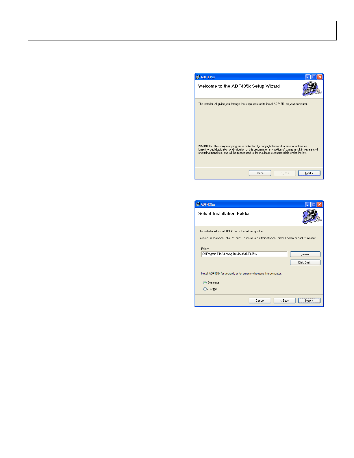
Windows XP Software Installation Guide
Figure 4. Windows XP ADF435x Software Installation, Setup Wizard
1. Click Next.
Figure 5. Windows XP ADF435x Software Installation, Select Installation
Folder
2. Choose an installation directory and click Next.
10844-00410844-005
Rev. 0 | Page 5 of 20
Page 6
UG-435 Evaluation Board User Guide
10844-007
10844-009
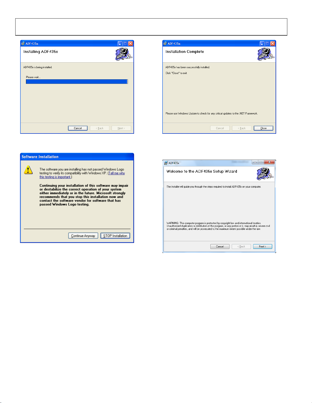
Figure 6. Windows XP ADF435x Software Installation, Confirm Installation
3. Click Next.
Figure 7. Windows XP ADF435x Software Installation, Logo Testing
4. Click Continue Anyway.
10844-006
Figure 8. Windows XP ADF435x Software Installation, Installation Complete
10844-008
5. Click Close.
Windows Vista/7 Software Installation Guide
Figure 9. Windows Vista/7 ADF435x Software Installation, Setup Wizard
1. Click Next.
Rev. 0 | Page 6 of 20
Page 7

Evaluation Board User Guide UG-435
Figure 10. Windows Vista/7 ADF435x Software Installation, Select
Installation Folder
2. Choose an installation directory and click Next.
Figure 11. Windows Vista/ 7 ADF435x Software Installation, Confirm Instal lation
3. Click Next.
10844-01010844-011
Figure 12. Windows Vista/7 ADF435x Software Installation, Start Installation
10844-01210844-013
4. Click Install.
Figure 13. Windows Vista/ 7 ADF435x Software Installation, Installation
Complete
5. Click Close.
Rev. 0 | Page 7 of 20
Page 8

UG-435 Evaluation Board User Guide
10844-015
10844-016
10844-017
Windows XP Driver Installation Guide
Figure 14. Windows XP USB Adapter Board Driver Installation, Found New
Hardware Wizard
1. Choose Yes, this time only, and click Next.
Figure 15. Windows XP USB Adapter Board Driver Installation, Installation
Options
2. Click Next.
Note that Figure 15 may list Analog Devices RFG.L Eval
Board instead of ADF4xxx USB Adapter Board.
10844-014
Figure 16. Windows XP USB Adapter Board Driver Installation, Logo Testing
3. Click Continue Anyway.
Figure 17. Windows XP USB Adapter Board Driver Installation, Complete
Installation
4. Click Finish.
Rev. 0 | Page 8 of 20
Page 9

Evaluation Board User Guide UG-435
10844-018
EVALUATION BOARD SOFTWARE
The control software for the EVAL-ADF4351EB1Z accompanies
the EVAL-ADF4351EB1Z on a CD. To install the software, see
the Software Installation section.
To run the software, click the ADI ADF435x file on the desktop
or in the Start menu.
On the Select Device and Connection tab, choose your device,
your connection method, and click Connect.
Confirm that SDP board connected, ADF4xxx USB Adapter
Board connected, or Analog Devices RFG.L Eval Board
connected is displayed at the bottom left of the window.
Otherwise, the software has no connection to the evaluation
board.
Note that, when connecting the board, it takes about 5 sec to
10 sec for the status label to change.
Under the File menu, the current settings can be saved to and
loaded from, a text file.
Figure 18. Software Front Panel Display—Select Device and Connection
Rev. 0 | Page 9 of 20
Page 10

UG-435 Evaluation Board User Guide
10844-019
The Main Controls tab controls the PLL settings (see Figure 19).
Use the Reference Frequency text box to set the correct
reference frequency and the reference frequency divider. The
default reference on the software window is 25 MHz.
Use the RF Settings section to control the output frequency.
You can type the desired output frequency in the RF Frequency
text box (in megahertz).
In the Registers tab, you can manually input the desired value
to be written to the registers.
In the Sweep and Hop tab, you can make the device sweep a
range of frequencies, or hop between two set frequencies.
In the Registers section at the bottom of the Main Controls
tab, the values to be written to each register are displayed. If the
background on the text box is green, the value displayed is
different from the value actually on the device. Click Write Rx
(where x = 0 to 5) to write that value to the device.
Figure 19. Software Front Panel Display—Main Controls
Rev. 0 | Page 10 of 20
Page 11

Evaluation Board User Guide UG-435
SPECTRUM
ANALYZER
PC
EXTERNAL DC
SUPPLY
EXTERNAL DC
GND
TCXO
ADF4351
LOOP
FILTER
LOCK DETECT LED
USB
POWER
LED
PLL
POWER
LED
USB
POWER
SWITCH
EXTERNAL
POWER
SWITCH
USB CRYSTAL
AND PROCESSO R
50Ω
TERMINATION
REFERENCE I N/
REFERENCE O UT
REFERENCE (OPTIONAL)
10844-000
EVALUATION AND TEST
To evaluate and test the performance of the ADF4351, use the
following procedure:
1. Install ADF435x software.
2. Connect the evaluation board to a PC using the supplied
USB cable. Follow the hardware driver installation
procedure that appears.
3. Connect spectrum analyzer to Connector RF
4. Connect 50 Ω termination to RF
OUT
A−.
OUT
A+.
5. Run the ADF435x software.
6. Select the USB board and the ADF4351 device in the
Select Device and Connection tab of the software front
panel window.
7. In the software window, click Write All Registers. See
Figure 19 for the suggested setup.
8. Measure the output spectrum. Figure 20 shows a
phase noise plot at 2.5 GHz output.
9. Different combinations of reference and PFD frequency
may require changes to the REFIN stage or PFD frequency.
Low output frequencies may require different output stage
elements.
10844-020
Figure 20. Spectrum Analyzer Display
Figure 21. Typical Evaluation Setup
Rev. 0 | Page 11 of 20
Page 12

UG-435 Evaluation Board User Guide
10844-022
EVALUATION BOARD SCHEMATICS AND ARTWORK
Figure 22. Evaluation Board Schematic (Page 1)
Rev. 0 | Page 12 of 20
Page 13

Evaluation Board User Guide UG-435
10844-023
Figure 23. Evaluation Board Schematic (Page 2)
Rev. 0 | Page 13 of 20
Page 14

UG-435 Evaluation Board User Guide
10844-024
Figure 24. Evaluation Board Schematic (Page 3)
Rev. 0 | Page 14 of 20
Page 15

Evaluation Board User Guide UG-435
10844-025
10844-026
Figure 25. Top Side
Figure 26. Layer 2 (GND Plane)
Rev. 0 | Page 15 of 20
Page 16

UG-435 Evaluation Board User Guide
10844-027
10844-028
Figure 27. Layer 3 (Power Plane)
Figure 28. Bottom Side
Rev. 0 | Page 16 of 20
Page 17

Evaluation Board User Guide UG-435
3
C11, C12, C49
Ceramic capacitor, 1 nF, 0603, 50 V, NP0
2
C47, C50
Ceramic capacitor, 1 µF, 0603, 25 V, X5R
3
R7, R44, R45
Resistor 100 Ω 0603 SMD
3
R39, R49, R50
Resistor, 2.2 kΩ, 0603, SMD
2
U2, U3
ADP150-TSOT TSOT-5 linear regulator
1
GND
Black 4 mm banana socket
ORDERING INFORMATION
BILL OF MATERIALS
Table 1.
Qty Reference Designator Description
1 C1 Ceramic capacitor, 2.7 nF, 0603, 100 V, X7R
1 C2 Ceramic capacitor, 47 nF, 0603, 25 V, X7R
1 C3 Ceramic capacitor, 680 pF, 0603, 50 V, X7R, SMD
4 C4, C27, C32, C34 Capacitor, 1 µF, 0603, 10 V, X5R
21 C5, C8, C10, C13, C17, C18, C21, C22,
C25, C28, C29, C30, C53, C54, C55, C57,
C58, C59, C60, C61, C69
10 C6, C7, C14, C15, C16, C19, C20, C23,
C52, C56
1 C9 Ceramic capacitor+, 1 µF, 0805, RTAJ_A, 16 V, X7R
2 C24, C36 Ceramic capacitor, 120 pF, 0402, 50 V, NP0
2 C26, C35 Ceramic capacitor, 1 nF, 0402, 50 V, NP0
2 C31, C62 Ceramic capacitor, 12 pF, 0603, 50 V, NPO, SMD
1 C33 Capacitor+, 22 µF, 16 V, RTAJ_B, tantalum TAJ-B 22UF, 10%
2 D1, D6 0805 green LED
2 D2, D4 Zener diode, 6.8 V, SOT23, 350 MW
1 D5 0805 red LED
2 L1, L4 Inductor, 0 Ω 0402 SMD resistor
2 L2, L3 Inductor, 7.5 nH L0402 0402 chip inductor
1 L10 0603 ferrite bead
1 R1 Resistor, 360 Ω, 0603, SMD
2 R2, R38 Resistor, 1 kΩ, 0603, SMD
11 R3, R4, R10, R13, R20, R22, R51, R52,
R56, R58, R59
13 R5, R6, R8, R9, R11, R14, R18, R21,
R46, R53, R54, R55, R57
Ceramic capacitor, 0.1 µF, 0402, 16 V, X7R
Ceramic capacitor, 10 pF, 0402, 50 V, NP0
Resistor, 0 Ω, 0603, SMD
Resistor location, DNI, 0603—not inserted
1 R12 Resistor 4.7 kΩ, 0603, SMD
4 R15, R16, R17, R19 Resistor, 10 kΩ, 0603, SMD
2 R23, R27 Resistor, 0 Ω, 0402, SMD
3 R24 to R26 Resistor, DNI, 0603, SMD
1 R40 Resistor, 140 kΩ, 0603, SMD
1 R41 Resistor, 78.7 kΩ, 0603, SMD
13 3V3_USB, 5V_USB, AVDD, CE, CLK, DATA,
LD, LE, MUXOUT, PDRF, T1, T2, VOUT
3 REFIN, RFOUTA+, RFOUTA− SMA_CARD_EDGE_RF, end-launch 50 Ω SMA jack
2 S1, S2 SW_POWER SW_SIP-3P PCB mount SPDT switch
1 U1 ADF4351 LFCSP-32 PLL
1 U5 ADP3334 MSO8 adjustable LDO regulator
1 U6 CY7C68013-CSP, LFCSP-56_RP, USB microcontroller
1 U7 24LC64, SO8NB, 64K I2C serial EEPROM
1 USB USB mini-B connector (usb-otg)
1 VSUPPLY Red 4 mm banana socket
1 Y1 OSC_TCXO_IT3200C 26MHz TCXO-IT3200C TCXO
1 Y1 (ALT) OSC_TCXO-RAKON-TXO200B, 25 MHz, SMD temperature compensated crystal oscillator
1 Y2 XTAL1-CSM-8A, 24.0 MHz, XTAL-CSM-8A, SMD crystal
Red test point
Rev. 0 | Page 17 of 20
Page 18

UG-435 Evaluation Board User Guide
NOTES
Rev. 0 | Page 18 of 20
Page 19

Evaluation Board User Guide UG-435
NOTES
Rev. 0 | Page 19 of 20
Page 20

UG-435 Evaluation Board User Guide
NOTES
I2C refers to a communications protocol originally developed by Philips Semiconductors (now NXP Semiconductors).
ESD Caution
ESD (electrostatic discharge) sensitive device. Charged devices and circuit boards can discharge without detection. Although this product features patented or proprietary protection
circuitry, damage may occur on devices subjected to high energy ESD. Therefore, proper ESD precautions should be taken to avoid performance degradation or loss of functionality.
Legal Terms and Conditions
By using the evaluation board discussed herein (together with any tools, components documentation or support materials, the “Evaluation Board”), you are agreeing to be bound by the terms and conditions
set forth below (“Agreement”) unless you have purchased the Evaluation Board, in which case the Analog Devices Standard Terms and Conditions of Sale shall govern. Do not use the Evaluation Board until you
have read and agreed to the Agreement. Your use of the Evaluation Board shall signify your acceptance of the Agreement. This Agreement is made by and between you (“Customer”) and Analog Devices, Inc.
(“ADI”), with its principal place of business at One Technology Way, Norwood, MA 02062, USA. Subject to the terms and conditions of the Agreement, ADI hereby grants to Customer a free, limited, personal,
temporary, non-exclusive, non-sublicensable, non-transferable license to use the Evaluation Board FOR EVALUATION PURPOSES ONLY. Customer understands and agrees that the Evaluation Board is provided
for the sole and exclusive purpose referenced above, and agrees not to use the Evaluation Board for any other purpose. Furthermore, the license granted is expressly made subject to the following additional
limitations: Customer shall not (i) rent, lease, display, sell, transfer, assign, sublicense, or distribute the Evaluation Board; and (ii) permit any Third Party to access the Evaluation Board. As used herein, the term
“Third Party” includes any entity other than ADI, Customer, their employees, affiliates and in-house consultants. The Evaluation Board is NOT sold to Customer; all rights not expressly granted herein, including
ownership of the Evaluation Board, are reserved by ADI. CONFIDENTIALITY. This Agreement and the Evaluation Board shall all be considered the confidential and proprietary information of ADI. Customer may
not disclose or transfer any portion of the Evaluation Board to any other party for any reason. Upon discontinuation of use of the Evaluation Board or termination of this Agreement, Customer agrees to
promptly return the Evaluation Board to ADI. ADDITIONAL RESTRICTIONS. Customer may not disassemble, decompile or reverse engineer chips on the Evaluation Board. Customer shall inform ADI of any
occurred damages or any modifications or alterations it makes to the Evaluation Board, including but not limited to soldering or any other activity that affects the material content of the Evaluation Board.
Modifications to the Evaluation Board must comply with applicable law, including but not limited to the RoHS Directive. TERMINATION. ADI may terminate this Agreement at any time upon giving written notice
to Customer. Customer agrees to return to ADI the Evaluation Board at that time. LIMITATION OF LIABILITY. THE EVALUATION BOARD PROVIDED HEREUNDER IS PROVIDED “AS IS” AND ADI MAKES NO
WARRANTIES OR REPRESENTATIONS OF ANY KIND WITH RESPECT TO IT. ADI SPECIFICALLY DISCLAIMS ANY REPRESENTATIONS, ENDORSEMENTS, GUARANTEES, OR WARRANTIES, EXPRESS OR IMPLIED, RELATED
TO THE EVALUATION BOARD INCLUDING, BUT NOT LIMITED TO, THE IMPLIED WARRANTY OF MERCHANTABILITY, TITLE, FITNESS FOR A PARTICULAR PURPOSE OR NONINFRINGEMENT OF INTELLECTUAL
PROPERTY RIGHTS. IN NO EVENT WILL ADI AND ITS LICENSORS BE LIABLE FOR ANY INCIDENTAL, SPECIAL, INDIRECT, OR CONSEQUENTIAL DAMAGES RESULTING FROM CUSTOMER’S POSSESSION OR USE OF
THE EVALUATION BOARD, INCLUDING BUT NOT LIMITED TO LOST PROFITS, DELAY COSTS, LABOR COSTS OR LOSS OF GOODWILL. ADI’S TOTAL LIABILITY FROM ANY AND ALL CAUSES SHALL BE LIMITED TO THE
AMOUNT OF ONE HUNDRED US DOLLARS ($100.00). EXPORT. Customer agrees that it will not directly or indirectly export the Evaluation Board to another country, and that it will comply with all applicable
United States federal laws and regulations relating to exports. GOVERNING LAW. This Agreement shall be governed by and construed in accordance with the substantive laws of the Commonwealth of
Massachusetts (excluding conflict of law rules). Any legal action regarding this Agreement will be heard in the state or federal courts having jurisdiction in Suffolk County, Massachusetts, and Customer hereby
submits to the pers onal jurisdiction and venu e of such courts. The United Nations Conventi on on Contracts for the Internation al Sale of Goods shall not apply to this Agreement and is expressly disclaimed.
©2012 Analog Devices, Inc. All rights reserved. Trademarks and
registered trademarks are the property of their respective owners.
UG10844-0-6/12(0)
Rev. 0 | Page 20 of 20
 Loading...