

Page 1
Evaluation Board User Guide
10653-001
One Technology Way • P.O. Box 9106 • Norwood, MA 02062-9106, U.S.A. • Tel: 781.329.4700 • Fax: 781.461.3113 • www.analog.com
UG-402
iCoupler ADuM3070 Isolated Switch Regulator
With Integrated Feedback Evaluation Board
FEATURES
2 independent ADuM3070 circuits including 2.5 kV rms
isolated dc-to-dc converters
Single supply
5 V in to 5 V out (regulated)
Reconfigurable to 5 V in to 3.3 V out or 3.3 V in
to 3.3 V out
Double supply
5 V in to 15 V out (regulated) and 7.5 V out (unregulated)
Reconfigurable to 5 V in to 12 V out (regulated) and 6 V
out (unregulated)
Footprints for Coilcraft and Halo transformer options
Multiple switching frequency options
SUPPORTED iCoupler MODELS
ADuM3070
GENERAL DESCRIPTION
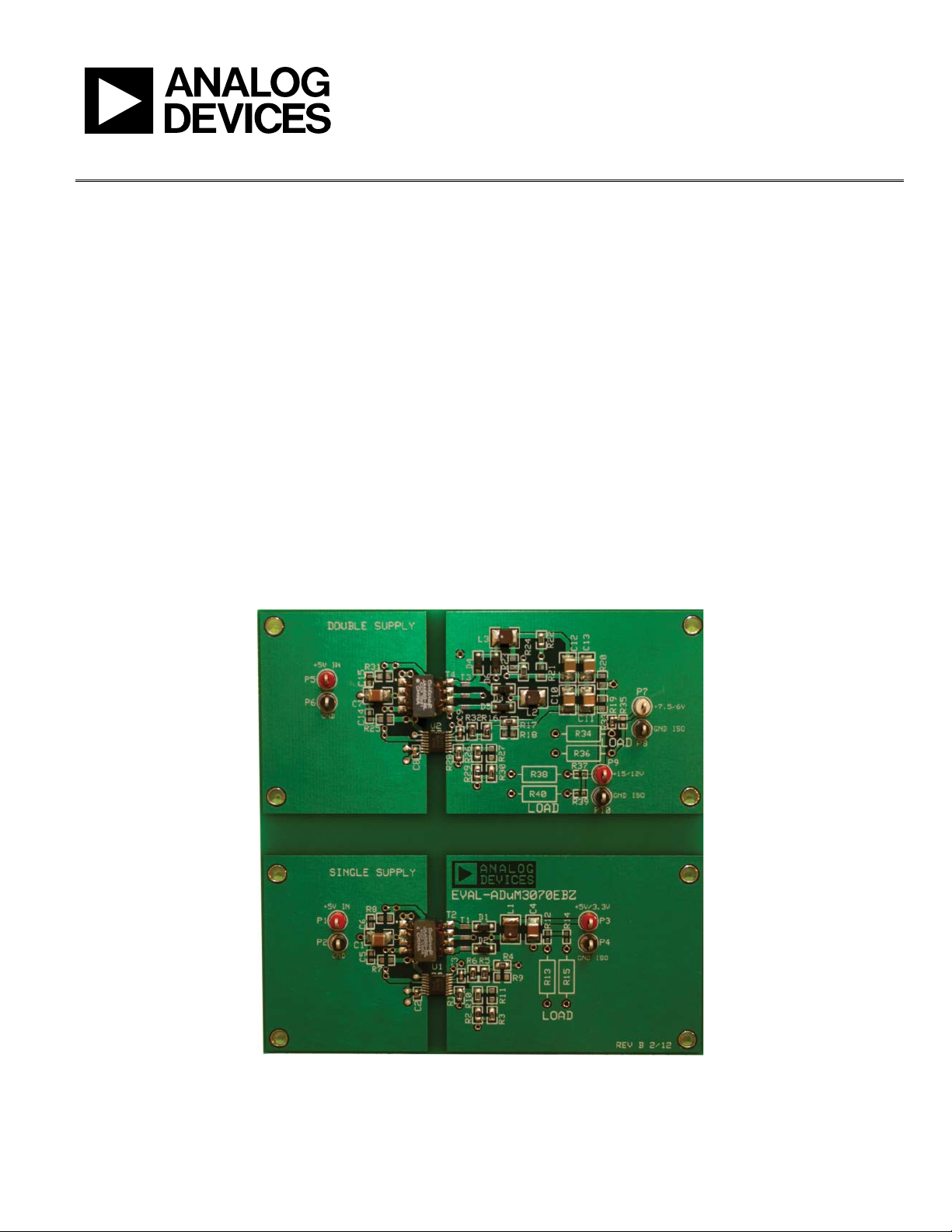
The EVA L-ADuM3070EBZ demonstrates two separate
applications for the ADuM3070 isolated switch regulator with
integrated feedback. It has two independent power supply
circuits: a double supply and a single supply. The switching
frequency can be set from 200 kHz to 1000 kHz. The board
supports a variety of I/O configurations and multiple transformer options. It is equipped with two ADuM3070 isolators.
ADUM3070 EVALUATION BOARD
PLEASE SEE THE LAST PAGE FOR AN IMPORTANT
WARNING AND LEGAL TERMS AND CONDITI ONS.
Figure 1. Double Supply (Top) and Single Supply (Bottom) Configurations
Rev. 0 | Page 1 of 12
Page 2

UG-402 Evaluation Board User Guide
TABLE OF CONTENTS
Features .............................................................................................. 1
Supported iCoupler Models ............................................................ 1
General Description ......................................................................... 1
ADuM3070 Evaluation Board ........................................................ 1
Revision History ............................................................................... 2
Single Supply ..................................................................................... 3
Terminals ....................................................................................... 3
Transformer Selection .................................................................. 3
Switching Frequency Options ..................................................... 3
Other Input and Isolated Output Supply Options ................... 4
REVISION HISTORY
5/12—Revision 0: Initial Version
Schematic........................................................................................5
Double Supply ....................................................................................6
Terminals ........................................................................................6
Transformer Selection ..................................................................7
Switching Frequency Options......................................................7
Other Secondary Isolated Supply Configurations ....................8
Schematic........................................................................................8
Evaluation Board Layout ..................................................................9
Ordering Information .................................................................... 10
Bill of Materials ........................................................................... 10
Rev. 0 | Page 2 of 12
Page 3
Evaluation Board User Guide UG-402
10653-002
10653-003
SINGLE SUPPLY
Two independent and isolated circuits comprise the ADuM3070
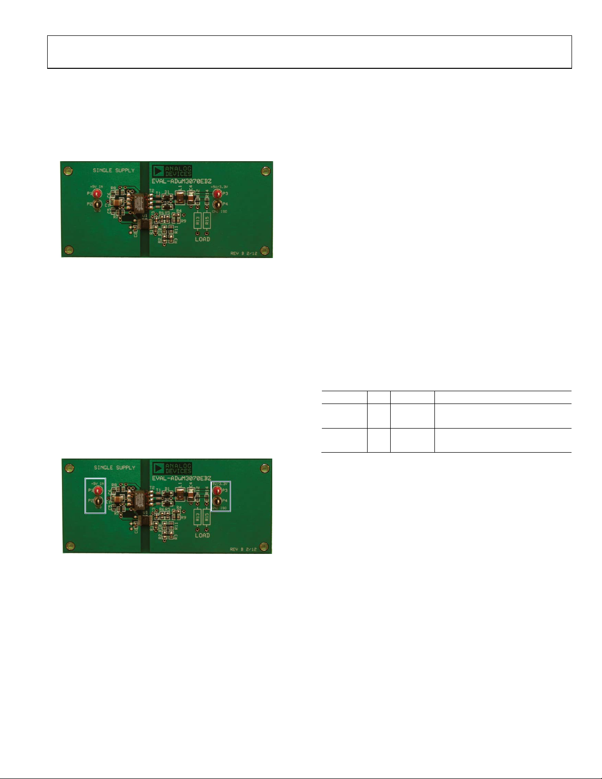
evaluation board. The lower half of the board, shown in Figure 2,
is for a single power supply configuration (see the ADuM3070
data sheet for applications information about the ADuM3070 in
this configuration).
Figure 2. Single Supply Configuration
The single supply is configured as a 5 V secondary isolated
supply with a 5 V primary input supply, which can provide up
to 2.5 W of regulated, isolated power. It can be reconfigured for
a 3.3 V secondary isolated supply with a 5 V or 3.3 V primary
input supply (see the Other Input and Isolated Output Supply
Options section). Figure 9 shows the single supply schematic.
TERMINALS
The single supply has terminal blocks on Side 1 (the primary/
power supply input side) and Side 2 (the secondary/power supply
output side). A 4.3 mm isolation barrier separates Side 1 and
Side 2. Figure 3 shows these terminal locations.
Tabl e 1 summarizes the functions of the terminal connections.
They are described in detail in the Input Power Connections
and Output Power Connections sections.
V
supplies the voltage to the transformer primary and to the
DD1
ADuM3070 supply voltage, V
for additional information about the V
and V
are bypassed by a 47 µF ceramic capacitor (C1) and a
DDA
(see the ADuM3070 data sheet
DDA
pin function). V
DDA
DD1
0.1 µF local bypass capacitor (C2) located close to the ADuM3070.
R7, R8, C5, and C6 are provided for an optional and unpopulated
snubber, which can be used to reduce radiated emissions.
Power is transferred to Side 2 by a regulated push-pull converter
comprising the ADuM3070 (U1), an external transformer (T1
or T2), and other components (see the ADuM3070 data sheet
for an explanation of this circuit functionality).
Output Power Connections
An output load can be connected to P3 (labeled +5V/3.3V on the
silkscreen and not labeled on the schematic), which is the isolated, regulated 5 V output supply. Connect the return of the
load to P4, which is the Side 2 ground reference. P4 is labeled
GND ISO on the silkscreen and GND2 on the schematic. This
supply can provide up to 500 mA in the default 5 V primary
input supply, 5 V secondary isolated supply configuration.
Figure 5 through Figure 8 in this user guide show how the
power supply’s efficiency varies with load current, switching
frequency, and temperature.
Table 1. Single Supply Terminal Function Descriptions
Terminal Pin Label Description
P1 1 +5V IN Side 1 5 V primary input supply
P2 1 GND Side 1 ground reference
P3 1 +5V/3.3V Side 2 5 V secondary isolated supply
P4 1 GND ISO Side 2 ground reference
Care must be taken to avoid driving the V
output with an
DD2
external voltage because this can result in permanent damage to
the ADuM3070.
Figure 3. Single Supply Terminals
Input Power Connections
Connect 5 V to P1, labeled +5V IN (or +3.3 V for a
3.3 V primary input supply with a 3.3 V secondary isolated
supply). Connect the negative supply to P2, labeled GND
(GND1 on the schematic). These are the only off-board
connections required for the single supply to function.
TRANSFORMER SELECTION
The EVA L-ADuM3070EBZ supports multiple transformer
options. The single supply is equipped with a Halo TGSAD260V6LF (T1) or a Coilcraft JA4631-BL (T2) 1:2 turns ratio
transformer. The Coilcraft footprint is offset to the left of the
Halo footprint. Figure 5 and Figure 7 show the efficiency curves
for the single supply operating with a Coilcraft and a Halo
transformer, respectively.
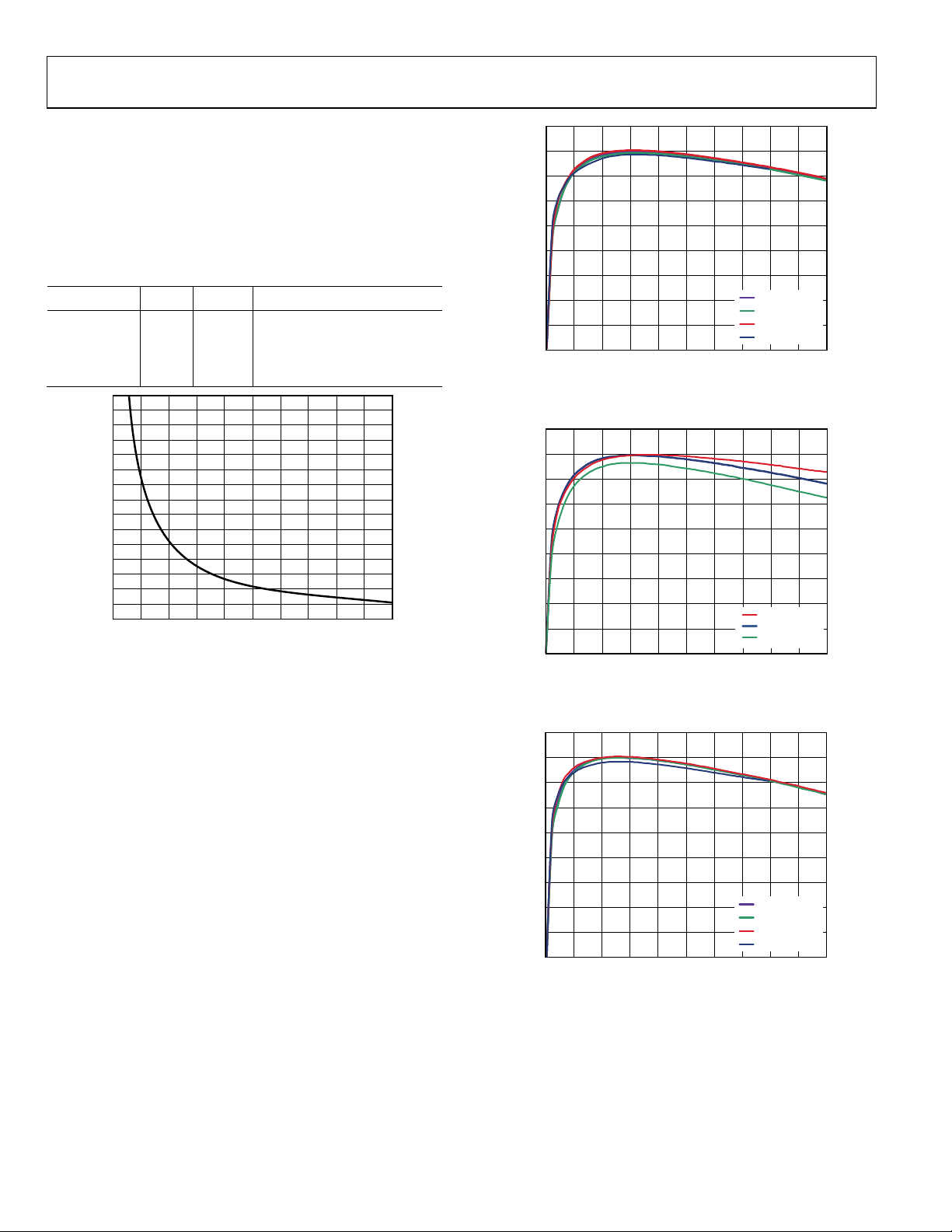
SWITCHING FREQUENCY OPTIONS
The resistor connected from the ADuM3070 oscillator control
pin (OC) to ground sets the single supply switching frequency.
Figure 4 shows the relationship between this resistance and the
converter switching frequency. The EVA L-ADuM3070EBZ can
be configured with 0 Ω, 0805 resistors to four different preset
switching frequencies. Short-circuiting R10 sets R1 (300 kΩ)
and R2 (150 kΩ) in parallel, and short-circuiting R11 sets R1 and
R3 (100 kΩ) in parallel. Tabl e 2 lists the switching frequencies
that can be selected by short- or open-circuiting R10 and R11.
Rev. 0 | Page 3 of 12
Page 4
UG-402 Evaluation Board User Guide
1500
1400
1300
1200
1100
1000
90
0
800
700
600
500
400
300
200
100
0
0 50 100 150 200 250 30
0 350 400 450 500
f
SW
(kHz)
R
OC
(
Ω)
10653-004
90
80
70
60
50
40
30
20
10
0
0 50045040035030025020015010050
EFFICIENCY (%)
LOAD CURRENT (mA)
f
SW
= 1MHz
f
SW
= 700kHz
f
SW
= 500kHz
f
SW
= 200kHz
10653-005
90
80
70
60
50
40
30
20
10
0
0 50045040035030025020015010050
EFFICIENCY (%)
LOAD CURRENT (mA)
TA= –40°C
T
A
= +25°C
T
A
= +105°C
10653-006
90
80
70
60
50
40
30
20
10
0
0 50045040035030025020015010050
EFFICIENCY (%)
LOAD CURRENT (mA)
f
SW
= 1MHz
f
SW
= 700kHz
f
SW
= 500kHz
f
SW
= 200kHz
10653-007
The user can select a different switching frequency by removing
R10 and R11 and then choosing R1 based on Figure 4. The
board is configured for the 500 kHz setting by default. Figure 5
and Figure 7 show how the switching frequency affects the
supply’s efficiency with either transformer installed. Figure 6
shows how the efficiency curve varies over temperature with a
500 kHz switching frequency.
Table 2. Switching Frequency Selection
R10 R11 ROC Switching Frequency
Open Open 300 kΩ 200 kHz
0 Ω Open 100 kΩ 500 kHz
Open 0 Ω 75 kΩ 700 kHz
0 Ω 0 Ω 50 kΩ 1 MHz
Figure 5. 5 V In to 5 V Out Efficiency with 1:2 Coilcraft Transformer at Various
Switching Frequencies
Figure 4. Switching Frequency vs. R
OTHER INPUT AND ISOLATED OUTPUT SUPPLY OPTIONS
The single supply can be configured to have a 3.3 V secondary
isolated supply with a 3.3 V or 5 V primary input supply. Shortcircuiting R4 by soldering a 0 Ω, 0805 resistor to R9 sets the
output supply for 3.3 V. The voltage at the feedback node (the
FB pin of the ADuM3070) should be the desired output voltage
divided to approximately 1.25 V. Having R9 open-circuited sets
the secondary isolated supply to 5 V, and having it short-circuited
sets the supply to 3.3 V. See the ADuM3070 data sheet for more
details on setting the secondary isolated output supply voltage.
Figure 8 shows how the single supply efficiency curve changes
when it is reconfigured for either of these supply options.
Resistance
OC
Figure 6. 5 V In to 5 V Out Efficiency with 1:2 Coilcraft Transformer at 500 kHz
over Temperature
Figure 7. 5 V In to 5 V Out Efficiency with 1:2 Halo Transformer at Various
Switching Frequencies
Rev. 0 | Page 4 of 12
Page 5

Evaluation Board User Guide UG-402
90
80
70
60
50
40
30
20
10
0
0 50045040035030025020015010050
EFFICIENCY (%)
LOAD CURRENT (mA)
5V IN TO 5V OUT
5V IN TO 3.3V OUT
3.3V IN TO 3.3V O UT
10653-008
10653-009
Figure 8. Single Supply Efficiency for Various Output Configurations with
1:2 Coilcraft Transformer at 500 kHz
SCHEMATIC
Figure 9. Single Supply Schematic
Rev. 0 | Page 5 of 12
Page 6

UG-402 Evaluation Board User Guide
10653-010
10653-011
DOUBLE SUPPLY
The second power supply implemented with the ADuM3070 on
this evaluation board is a double supply. This circuit, which is
shown in Figure 10, is located on the top half of the board. The
ADuM3070 data sheet also describes the ADuM3070 in this
configuration. Figure 17 shows the schematic.
Figure 10. Double Supply Configuration
In its default configuration, the double supply provides a regulated
15 V output and an unregulated 7.5 V output, which are isolated
from the 5 V primary input supply. The double supply is capable of delivering up to 140 mA to external loads. The isolated
data channels on Side 2 load the secondary isolated supply and
reduce the total available current. The double supply can be
reconfigured as 12 V (regulated) and 6 V (unregulated) secondary
isolated supplies or as positive and negative supplies. See the
Other Secondary Isolated Supply Configurations section for
more details.
Figure 11. Double Supply Terminals
TERMINALS
The double supply has terminal blocks on Side 1 (the primary/
power supply input side) and Side 2 (the secondary/power supply
output side). A 4.3 mm isolation barrier separates Side 1 and
Side 2. Figure 11 shows these terminals. Ta b l e 3 summarizes the
functions of the terminal connections. They are described in
detail in the Input Power Connections and Output Power
Connections sections.
Input Power Connections
Connect 5 V to P5, labeled +5V IN. Connect the supply
negative to P6, labeled GND (GND3 on the schematic). These
are the only off-board connections required for the double
supply to function.
V
supplies the voltage to the transformer primary and to the
DD2
ADuM3070 supply voltage, V
for additional information about the V
(see the ADuM3070 data sheet
DDA
pin function). V
DDA
DD2
and V
are bypassed by a 47 µF ceramic capacitor (C7) and a
DDA
0.1 µF local bypass capacitor (C8) located close to the ADuM3070.
R25, R31, C14, and C15 are provided for an optional and
unpopulated snubber, which can be used to reduce radiated
emissions.
Output Power Connections
Output loads can be connected to P7 and P9, labeled VISO1
and VISO2, respectively, in the schematic and +7.5V/6V and
+15/12V, respectively, on the silkscreen, which are the isolated,
unregulated 7.5 V and regulated 15 V output supplies. Connect
the return of the load to P8 and P10, which are labeled GND
ISO on the silkscreen and GND4 in the schematic.
Side 2 is powered by the secondary isolated 15 V supply. The
ADuM3070 internal low dropout regulator converts this voltage
to 5 V. The regulated 5 V supply powers the ADuM3070 secondary
side. Therefore, the ADuM3070 V
pin is 15 V and the V
REG
DD2
pin is 5 V. The 15 V supply connects to P9. The 7.5 V supply
connects to P7, which is labeled +7.5V/6V on the silkscreen and
VISO1 on the schematic. The Side 2 ground reference is tied to
P10. Note that the single and double supplies do not share
grounds, although they have the same names on the silkscreen.
The two supplies are isolated from each other with a greater than
15 mm gap. See the ADuM3070 data sheet for an explanation of
the double supply theory of operation. Figure 12 through Figure 15
show efficiency curves for the double supply with the +15/+12 V
isolated output supply connected to V
Powering V
V
can be powered by the unregulated 7.5 V supply, which
REG
from the Unregulated 7.5 V Supply
REG
REG
.
results in higher efficiency. However, when the 15 V supply is
unloaded, the unregulated 7.5 V supply may drop to about 3 V,
which may not be high enough to power the ADuM3070
secondary side. This may cause the double supply to run open
loop, leaving the 15 V supply unregulated. Using 15 V for V
REG
ensures that the secondary side of the ADuM3471 powers up
under light load conditions. Move the 0 Ω, 0805 resistor from
R19 to R20 to power Side 2 from the 7.5 V supply.
Care must be taken to avoid driving the V
output because
DD2
this can result in permanent damage to the ADuM3070.
Table 3. Double Supply Terminal Function Descriptions
Terminal Pin Label Description
P5 1 +5V IN Side 1 5 V primary input supply
P6 1 GND Side 1 ground reference
P7 1 +7.5V/6V
P8 1 GND ISO Side 2 ground reference
P9 1 +15V/12V
P10 1 GND ISO Side 2 ground reference
Side 2 7.5 V secondary isolated
supply (regulated)
Side 2 15 V secondary isolated
supply (regulated)
Rev. 0 | Page 6 of 12
Page 7

Evaluation Board User Guide UG-402
90
80
70
60
50
40
30
20
10
0
0 140
EFFICIENCY (%)
LOAD CURRENT (mA)
10 20 30 40 50 60 70 80 90 100 110 120 130
f
SW
= 1MHz
f
SW
= 700kHz
f
SW
= 500kHz
f
SW
= 200kHz
10653-012
90
80
70
60
50
40
30
20
10
0
0 140
EFFICIENCY (%)
LOAD CURRENT (mA)
10 20 30 40 50 60 70 80 90 100 110 120 130
T
A
= –40°C
T
A
= +25°C
T
A
= +105°C
10653-013
90
80
70
60
50
40
30
20
10
0
0 140
EFFICIENCY (%)
LOAD CURRENT (mA)
10 20 30 40 50 60 70 80 90 100 110 120 130
TA= –40°C
T
A
= +25°C
T
A
= +105°C
10653-014
80
0
0 70
EFFICIENCY (%)
LOAD CURRENT (mA)
10
20
30
40
50
60
70
5 10 15 20 25 30 35 40 45 50 55 60 65
5V IN TO 12V O UT
5V IN TO 15
V OUT
10653-015
TRANSFORMER SELECTION
The EVA L-ADuM3070EBZ supports multiple transformer
options. The double supply is equipped with a Halo TGSAD290V6LF (T3) or a Coilcraft JA4650-BL (T4) 1:3 turns ratio
transformer. The Coilcraft footprint is directly to the left of the
Halo footprint (see the ADuM3070 data sheet for a details on
transformer selection with the ADuM3070). Figure 12 and
Figure 14 show the supply’s efficiency with a Coilcraft and a
Halo transformer, respectively, at different switching frequencies.
SWITCHING FREQUENCY OPTIONS
The resistor connected from the ADuM3070 OC pin to ground
sets the double supply switching frequency. Figure 4 shows the
relationship between this resistance and the converter switching
frequency. The EVA L -ADuM3070EBZ can be configured with
0 Ω, 0805 resistors to four different preset switching frequencies. Short-circuiting R26 sets R28 (300 kΩ) and R29 (150 kΩ)
in parallel, and short-circuiting R27 sets R28 and R30 (100 kΩ)
in parallel. Table 4 lists the switching frequencies that can be
selected by short- or open-circuiting R26 and R27. The user can
select a different switching frequency by removing R26 and R27
and then choosing R28 based on Figure 4. The board is configured for the 500 kHz setting by default. Figure 12 and Figure 14
show how the switching frequency affects the efficiency with
either transformer installed. Figure 13 shows how temperature
affects efficiency.
Figure 13. 5 V In to 15 V Out Efficiency with the 1:3 Coilcraft Transformer at
500 kHz and Various Temperatures
Table 4. Switching Frequency Selection
R26 R27 ROC Switching Frequency
Open Open 300 kΩ 200 kHz
0 Ω Open 100 kΩ 500 kHz
Open 0 Ω 75 kΩ 700 kHz
0 Ω 0 Ω 50 kΩ 1 MHz
Figure 12. 5 V In to 15 V Out Efficiency with the 1:3 Coilcraft Transformer at
Various Switching Frequencies
Figure 14. 5 V In to 15 V Out Efficiency with the 1:3 Halo Transformer at
Various Switching Frequencies
Figure 15. Double Supply Efficiency with the 1:5 Coilcraft Transformer for
Different Output Options at 500 kHz
Rev. 0 | Page 7 of 12
Page 8

UG-402 Evaluation Board User Guide
DOUBLE SUPP LY POSITIVE AND NEGATIVE SUPPLY
10653-016
10653-017
OTHER SECONDARY ISOLATED SUPPLY CONFIGURATIONS
The double supply can be configured for 12 V regulated and 6 V
unregulated secondary isolated supplies by short-circuiting R17
with a 0 Ω resistor for R18. The regulated supply voltage is set
by the fraction of it that is fed back to the ADuM3070 via the
voltage divider comprising R16, R17, R32, and R18. The voltage
at the feedback pin is 1.25 V. Wi t h R 18 open-circuited, the
ADuM3070 feedback voltage is approximately 1.25 V if VISO2
is 15 V. When R18 is short-circuited, the feedback voltage is
approximately 1.25 V if VISO2 is 12 V (see the ADuM3070 data
sheet for more details on setting the secondary isolated output
supply voltage). Figure 15 shows the efficiency curves for both
output settings at 500 kHz with the 1:5 Coilcraft transformer.
Positive and Negative Outputs
The double supply can be set up as a positive and negative ±15 V
supply by changing the transformer to a turns ratio 1CT:5CT
transformer (see the ADuM3070 data sheet for more information
on these transformers). Other changes begin with removing the
0 Ω resistors from R24 and R22 and inserting them into R23 and
R21. Short-circuiting R23 instead of R24 makes the 7.5 V/6 V P7
become the −15 V supply. Short-circuiting R21 instead of R22
connects the transformer center tap to the ground plane instead
of the node where L3, C12, and C13 are connected. Figure 16
shows which resistors should be short-circuited and opencircuited for the double supply or positive and negative supply
configurations. Note that the negative supply is unregulated.
The positive and negative supplies can be set for ±12 V instead
of ±15 V by short-circuiting R18.
Whereas the 15 V output can be regulated, the same problems
with regulation can happen as described in the Powering V
REG
from the Unregulated 7.5 V Supply section. In addition, the
−15 V supply can vary over a wide range because it is unregulated
and influenced by the changes that happen on the 15 V output.
Figure 16. Double Supply Configuration with 0 Ω Resistors (Red)
SCHEMATIC
Figure 17. Double Supply Schematic
Rev. 0 | Page 8 of 12
Page 9

Evaluation Board User Guide UG-402
EVALUATION BOARD LAYOUT
Figure 18. Top Layer: Power Fill
10653-018
Figure 20. Layer 3: Power Plane
10653-020
10653-021
Figure 19. Layer 2: Ground Plane
10653-019
Figure 21. Bottom Layer: Ground Fill
Rev. 0 | Page 9 of 12
Page 10

UG-402 Evaluation Board User Guide
ORDERING INFORMATION
BILL OF MATERIALS
Table 5.
Qty Reference Designator Description Supplier/Part Number
5 P1, P3, P5, P7, P9 TP-104 series test point, black Components Corp./TP-104-01-00
5 P2, P4, P6, P8, P10 TP-104 series test point, red Components Corp./TP-104-01-02
2 U1, U2 ADuM3070 Analog Devices, Inc.
6 D1 to D6 Schottky barrier rectifier, 0.5 A, 40 V, SMD, SOD-123 ON Semi/MBR0540
11 T1 Transformer, 1:2 turns ratio, SMD Halo/TGSAD-260V6LF
11 T2 Transformer, 1:2 turns ratio, SMD Coilcraft/JA4631-BL
11 T3 Transformer, 1:3 turns ratio, SMD Halo/TGSAD-290V6LF
11 T4 Transformer, 1:3 turns ratio, SMD Coilcraft/JA4650-BL
4 C2, C3, C8, C9 Capacitor ceramic, X7R, SMD, 0603, 0.1 µF AVX/0603YC104KAT2A
3 C1, C4, C7 Capacitor ceramic, X7R, SMD, 1210, 47 µF, 20%, 10 V Murata/GRM32ER71A476KE15L
4 C10 to C13 Capacitor ceramic, X7R, SMD, 1210, 22 µF, 20% 16 V Murata/GRM32ER71C226KE18L
3 L1 to L3 Inductor, SMD 1212, 47 µH, 20%, 1.25 Ω Murata/LQH3NPN470MM0
2 R1, R28 RES chip, SMD 0805, 300 kΩ, 1/8 W, 1% Yageo/RC0805FR-07300KL
2 R2, R29 RES chip, SMD 0805, 150 kΩ, 1/8 W, 1% Yageo/RC0805FR-07150KL
2 R3, R30 RES chip, SMD 0805, 100 kΩ, 1/8 W, 1% Panasonic/ECG/ERJ-6ENF1003V
2 R6, R32 RES chip, SMD 0805, 10.5 kΩ, 1/8 W, 1% Panasonic/ECG/ERJ-6ENF1052V
1 R4 RES chip, SMD 0805, 14.3 kΩ, 1/8 W, 1% Panasonic/ECG/ERJ-6ENF1432V
1 R5 RES chip, SMD 0805, 17.4 kΩ, 1/8 W, 1% Panasonic/ECG/ERJ-6ENF1742V
1 R17 RES chip, SMD 0805, 24.9 kΩ, 1/8 W, 1% Panasonic/ECG/ERJ-6ENF2492V
1 R16 RES chip, SMD 0805, 90.9 kΩ, 1/8 W, 1% Panasonic/ECG/ERJ-6ENF9092V
5 R19, R22, R24, R26, R10 RES chip, SMD 0805, 0 Ω, 1/8 W Panasonic/ECG/ERJ-6GEY0R00V
0
R11 to R15, R18, R20, R21, R23, R25, R27,
R31, R33 to R40, C5, C6, C14, C15
1
The board is populated with either Coilcraft or Halo transformers. Do not populate both T1 and T2 or T3 and T4.
Not populated N/A
Rev. 0 | Page 10 of 12
Page 11

Evaluation Board User Guide UG-402
NOTES
Rev. 0 | Page 11 of 12
Page 12

UG-402 Evaluation Board User Guide
NOTES
ESD Caution
ESD (electrostatic discharge) sensitive device. Charged devices and circuit boards can discharge without detection. Although this product features patented or proprietary protect ion
circuitry, damage may occur on devices subjected to high energy ESD. Therefore, proper ESD precautions should be taken to avoid performan ce degradation or loss of function ality.
Legal Terms and Conditions
By using the evaluation board discussed herein (together with any tools, components documentation or support materials, the “Evaluation Board”), you are agreeing to be bound by the terms and conditions
set forth below (“Agreement”) unless you have purchased the Evaluation Board, in which case the Analog Devices Standard Terms and Conditions of Sale shall govern. Do not use the Evaluation Board until you
have read and agreed to the Agreement. Your use of the Evaluation Board shall signify your acceptance of the Agreement. This Agreement is made by and between you (“Customer”) and Analog Devices, Inc.
(“ADI”), with its principal place of business at One Technology Way, Norwood, MA 02062, USA. Subject to the terms and conditions of the Agreement, ADI hereby grants to Customer a free, limited, personal,
temporary, non-exclusive, non-sublicensable, non-transferable license to use the Evaluation Board FOR EVALUATION PURPOSES ONLY. Customer understands and agrees that the Evaluation Board is provided
for the sole and exclusive purpose referenced above, and agrees not to use the Evaluation Board for any other purpose. Furthermore, the license granted is expressly made subject to the following additional
limitations: Customer shall not (i) rent, lease, display, sell, transfer, assign, sublicense, or distribute the Evaluation Board; and (ii) permit any Third Party to access the Evaluation Board. As used herein, the term
“Third Party” includes any entity other than ADI, Customer, their employees, affiliates and in-house consultants. The Evaluation Board is NOT sold to Customer; all rights not expressly granted herein, including
ownership of the Evaluation Board, are reserved by ADI. CONFIDENTIALITY. This Agreement and the Evaluation Board shall all be considered the confidential and proprietary information of ADI. Customer may
not disclose or transfer any portion of the Evaluation Board to any other party for any reason. Upon discontinuation of use of the Evaluation Board or termination of this Agreement, Customer agrees to
promptly return the Evaluation Board to ADI. ADDITIONAL RESTRICTIONS. Customer may not disassemble, decompile or reverse engineer chips on the Evaluation Board. Customer shall inform ADI of any
occurred damages or any modifications or alterations it makes to the Evaluation Board, including but not limited to soldering or any other activity that affects the material content of the Evaluation Board.
Modifications to the Evaluation Board must comply with applicable law, including but not limited to the RoHS Directive. TERMINATION. ADI may terminate this Agreement at any time upon giving written notice
to Customer. Customer agrees to return to ADI the Evaluation Board at that time. LIMITATION OF LIABILITY. THE EVALUATION BOARD PROVIDED HEREUNDER IS PROVIDED “AS IS” AND ADI MAKES NO
WARRANTIES OR REPRESENTATIONS OF ANY KIND WITH RESPECT TO IT. ADI SPECIFICALLY DISCLAIMS ANY REPRESENTATIONS, ENDORSEMENTS, GUARANTEES, OR WARRANTIES, EXPRESS OR IMPLIED, RELATED
TO THE EVALUATION BOARD INCLUDING, BUT NOT LIMITED TO, THE IMPLIED WARRANTY OF MERCHANTABILITY, TITLE, FITNESS FOR A PARTICULAR PURPOSE OR NONINFRINGEMENT OF INTELLECTUAL
PROPERTY RIGHTS. IN NO EVENT WILL ADI AND ITS LICENSORS BE LIABLE FOR ANY INCIDENTAL, SPECIAL, INDIRECT, OR CONSEQUENTIAL DAMAGES RESULTING FROM CUSTOMER’S POSSESSION OR USE OF
THE EVALUATION BOARD, INCLUDING BUT NOT LIMITED TO LOST PROFITS, DELAY COSTS, LABOR COSTS OR LOSS OF GOODWILL. ADI’S TOTAL LIABILITY FR OM ANY AND ALL CAUSES SHALL BE LIMITED TO THE
AMOUNT OF ONE HUNDRED US DOLLARS ($100.00). EXPORT. Customer agrees that it will not directly or indirectly export the Evaluation Board to another country, and that it will comply with all applicable
United States federal laws and regulations relating to exports. GOVERNING LAW. This Agreement shall be governed by and construed in accordance with the substantive laws of the Commonwealth of
Massachusetts (excluding conflict of law rules). Any legal action regarding this Agreement will be heard in the state or federal courts having jurisdiction in Suffolk County, Massachusetts, and Customer hereby
submits to the personal jurisdiction and venue of such courts. The United Nations Convention on Contracts for the International Sale of Goods shall not apply to this Agreement and is expressly disclaimed.
©2012 Analog Devices, Inc. All rights reserved. Trademarks and
registered trademarks are the property of their respective owners.
UG10653-0-5/12(0)
Rev. 0 | Page 12 of 12
 Loading...