

Page 1
Evaluation Board User Guide
UG-340
SDP BOARD10-LEAD Pu lSAR EVALUATION BOARD
VIN+
VIN–
IN+
IN–
ADC
+V
S
–V
S
GND
5V
ADSP-BF527
DSP
SPORT
SCK
SDO
CNV
OVDD
SDI
REF
+7.5V
VDD
ADA4841-1
ADA4841-1
A B
–2.5V
–2.5V
+7.5V
GND
VCM
AD8031
POWER SUP P LY CIRCUITRY
ADP7102, ADP7104, ADP2301
VIN = 9V
WALL ADAPTER
VDD
VSDP
GND
(OPTIONAL)
(OPTIONAL)
+7.5V/-2.5V 2.5V/5V +7.5V 3.3V +5V
ADR435
5V
GLUE
LOGIC
10322-001
One Technology Way • P. O. Box 9106 • Norwood, MA 02062-9106, U.S.A. • Tel: 781.329.4700 • Fax: 781.461.3113 • www.analog.com
Evaluation Board for the 10-Lead Family 14-/16-/18-Bit PulSAR ADCs
FEATURES
Full featured evaluation board for 10-lead PulSAR ADCs
Versatile analog signal conditioning circuitry
On-board reference, reference buffers, and ADC drivers
PC software for control and data analysis of time and
frequency domain
System demonstration board compatible (EVAL-SDP-CB1Z)
EQUIPMENT NEEDED
Evaluation kit contents
EVAL-AD7xxxSDZ
Wall adaptor power supply
Additional equipment needed
SDP board (EVAL-SDP-CB1Z) (optional)
Precision source
Cable (SMA input to evaluation board)
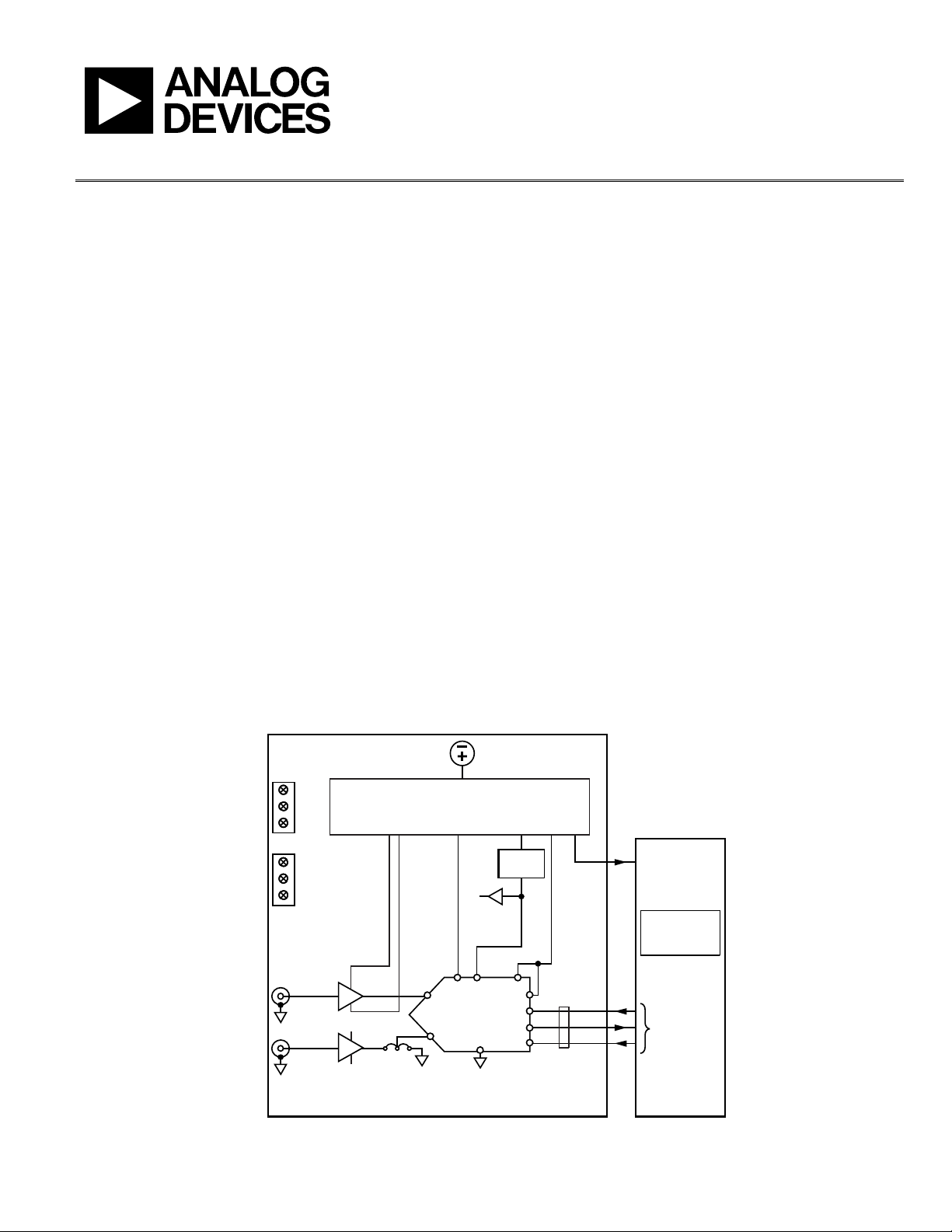
GENERAL DESCRIPTION
This evaluation board covers the following 10-lead PulSAR®
analog-to-digital converters (ADCs): AD7685 (16-bit), AD7686
(16-bit), AD7687 (16-bit), AD7688 (16-bit), AD7690 (18-bit),
AD7691 (18-bit), AD7693 (16-bit), AD7942 (14-bit), AD7946
(14-bit), AD7980 (16-bit), AD7982 (18-bit), AD7983 (16-bit),
AD7984 (18-bit), and AD7988-5 (16-bit).
These low power ADCs offer very high performance of up to
18 bits with throughputs ranging from 100 kSPS to 1.33 MSPS.
The evaluation board is designed to demonstrate the performance
of the ADCs and to provide an easy to understand interface for
a variety of system applications. A full description of these products
is available in their respective data sheets and should be consulted
when using this evaluation board.
The evaluation board is ideal for use with Analog Devices, Inc.,
system demonstration board (SDP). This evaluation board interfaces
to the SDP board via a 120-pin connector. SMA connectors, J6
and J10, are provided for the low noise analog signal source.
On-board components include a high precision buffered band gap
5.0 V reference (ADR435), a signal conditioning circuit with two
op amps (ADA4841-1), and a power supply to derive the necessary
voltage levels to supply all voltage needs.
PLEASE SEE THE LAST PAGE FOR AN IM PORTANT
WARNING AND LEGAL TERMS AND CONDITIONS.
SIMPLIFIED EVALUATION BOARD BLOCK DIAGRAM
Rev. 0 | Page 1 of 28
Figure 1.
Page 2

UG-340 Evaluation Board User Guide
TABLE OF CONTENTS
Features .............................................................................................. 1
Equipment Needed ........................................................................... 1
General Description ......................................................................... 1
Simplified Evaluation Board Block Diagram ................................ 1
Revision History ............................................................................... 2
Evaluation Board Kit Contents ....................................................... 3
Hardware Requirements .................................................................. 3
Evaluation Board Hardware ............................................................ 4
Setting Up the Evaluation Board ............................................... 4
Power Supplies .............................................................................. 4
Reference ....................................................................................... 4
Serial Interface .............................................................................. 4
Solder Links ................................................................................... 4
Analog Inputs ................................................................................ 4
Evalution Board Software................................................................ 5
Installing the Software ................................................................. 5
Installation Steps ........................................................................... 5
Board Operation/Connection Sequence ................................... 7
Running the Software with the Hardware Connected .............7
Running the Software Without Hardware .................................8
Software Operation ...........................................................................9
Description of User Panel ......................................................... 10
Wavef orm C aptu re .................................................................... 11
AC Te s ting —Histogram ............................................................ 12
DC Test i ng—Histogram ............................................................ 13
AC Te s ting —FFT Capture ........................................................ 13
Summary Tab .............................................................................. 14
Save File ....................................................................................... 15
Load File ...................................................................................... 15
Evaluation Board Schematics........................................................ 16
Troubleshooting .............................................................................. 25
Software ....................................................................................... 25
Hardware ..................................................................................... 25
Products on This Evaluation Board ............................................. 26
Related Links ............................................................................... 26
REVISION HISTORY
5/12—Revision 0: Initial Version
Rev. 0 | Page 2 of 28
Page 3

Evaluation Board User Guide UG-340
EVALUATIO N BOAR D KIT CONTENTS
Evaluation board for ADC of your choice, EVAL-AD7xxxSDZ
(U1 device is specific to the evaluation board ordered)
Business card with Analog Devices website address for
software and documentation
9 V wall wart
HARDWARE REQUIREMENTS
9 V wall wart (supplied)
Standard USB A to Mini-B USB cable
Signal source, ac source with low distortion, and dc source
with low noise
Band-pass filter suitable for 16- and 18-bit testing (value
based on signal frequency)
SDP board for data transfer to PC
Signal source and cables
Rev. 0 | Page 3 of 28
Page 4

UG-340 Evaluation Board User Guide
EVALUATION BOARD HARDWARE
SETTING UP THE EVALUATION BOARD
Figure 27 shows the evaluation board schematic. The board
consists of the ADC, U1, with a reference, U6, (ADR435) and
ADC drivers, U12 and U14 (ADA4841-1).
The evaluation board is a flexible design that enables the user to
adjust compensation components in addition to operating from
adjustable bench top power supply.
POWER SUPPLIES
The evaluation board requires power from a wall adapter. The
on-board power supply design is designed to operate from 9 V.
Table 1. Power Supplies Provided on the Board
Power Supply (V) Function Components Used
+5 SDP power ADP2301
+7.5 Positive rail ADP7102
−2.5 Negative rail ADP2301
+2.5/+5 ADC ADP7104
+3.3 V
(digital power) ADP7104
DRIVE
Each supply is decoupled where it enters the board and again at
each device. A single ground plane is used on this board to
minimize the effect of high frequency noise interference.
In addition to this, there is also the ability to power the board
from a bench top power supply. The screw terminals, J2 and J3, are
provided for this function. When bench power is used, the wall
wart and on-board power supply will no longer be required. Solder
links will also need to be changed. SL1 = B, SL2 = B, SL7 = B,
SL4 = B, and SL3 = B.
REFERENCE
An external 5 V reference (U6, ADR435) is used to supply the
ADCs direct ly.
SERIAL INTERFACE
The evaluation board uses the SPORT interface from the ADSP-
BF527 D S P.
A number of AND gates are used to clock and gate the SPORT
transfer to the ADC device. See U9, U10, and U11.
SOLDER LINKS
There is one three solder link option on the board. It is configured
depending on which generic of the ADC is on the specific
evaluation board as described in Tabl e 3.
Table 2. Table of Jumper Detail with Factory Default Setting
Link Setting Function Comment
SL2 A −VS Change to B if using bench
supplies
SL1 A +VS Change to B if using bench
supplies
SL3 A V_SDP Change to B if using bench
supplies
SL7 A VDD for
ADC
SL4 A VREF Change to B if using bench
Change to B if using bench
supplies
supplies
Table 3. Table of Jumpers Specific to Different ADCs
Link Setting Configuration Generic
SL10 A Differential
input
SL10 B Single-ended AD7685, AD7686, AD7942,
AD7684, AD7687, AD7690,
AD7691, AD7688, AD7982,
AD7984
AD7946, AD7980, AD7983
ANALOG INPUTS
The analog inputs to the evaluation board are SMA connectors,
J6 and J10. These inputs are buffered with dedicated amplifier
circuitry (U12 and U14) as shown in Figure 27. The circuit allows
for different configurations, input range scaling, filtering, addition
of a dc component, and use of different op amp and supplies.
The analog input amplifiers are set as unity-gain buffers at the
fac tor y. Th e amplifier positive rail is driven from 7.5 V (from
U13, ADP7102). The negative amplifier rail is driven from –V
(generated by U3, ADP2301).
The default configuration sets both U12 and U14 at midscale,
generated from a buffered reference voltage divider (VCM).
The evaluation board is factory configured for providing either
a single-ended path or a fully differential path as shown in Tabl e 3.
For dynamic performance, an FFT test can be done by applying
a very low distortion ac source.
For low frequency testing, the audio precision source can be
used directly as the outputs on these are isolated. Set the outputs for
balanced and floating ground. Different sources can be used;
however, most are single-ended sources that use a fixed output
resistance.
Because the evaluation board uses the amplifiers in unity-gain,
the noninverting input has a common-mode input with a series
590 Ω resistor, and it needs to be taken into account when directly
connecting a source (voltage divider).
S
Rev. 0 | Page 4 of 28
Page 5
Evaluation Board User Guide UG-340
10322-002
10322-003
10322-004
10322-005
EVALUTION BOARD SOFTWARE
INSTALLING THE SOFTWARE
The evaluation board software can be downloaded from the
relevant product page on the Analog Devices website.
Install the software prior to connecting the SDP board to the USB
port of the PC. This ensures that the SDP board is recognized
when it connects to the PC.
1. Start the Windows® operating system and download the
software from the relevant product page on the Analog
Devices website.
2. Unzip the downloaded file. Run the setup.exe file.
3. After installation is completed, power up the evaluation
board as described in the Power Supplies section.
4. Plug the evaluation board into the SDP board and the SDP
board into the PC using the USB cable included in the box.
5. When the software detects the evaluation board, proceed
through any dialog boxes that appear to finalize the
installation.
The default location for the software is the following:
C:\Program Files\Analog Devices\10 Lead PulSAR ADCs.
This location contains the executable software, data sheets, and
example files.
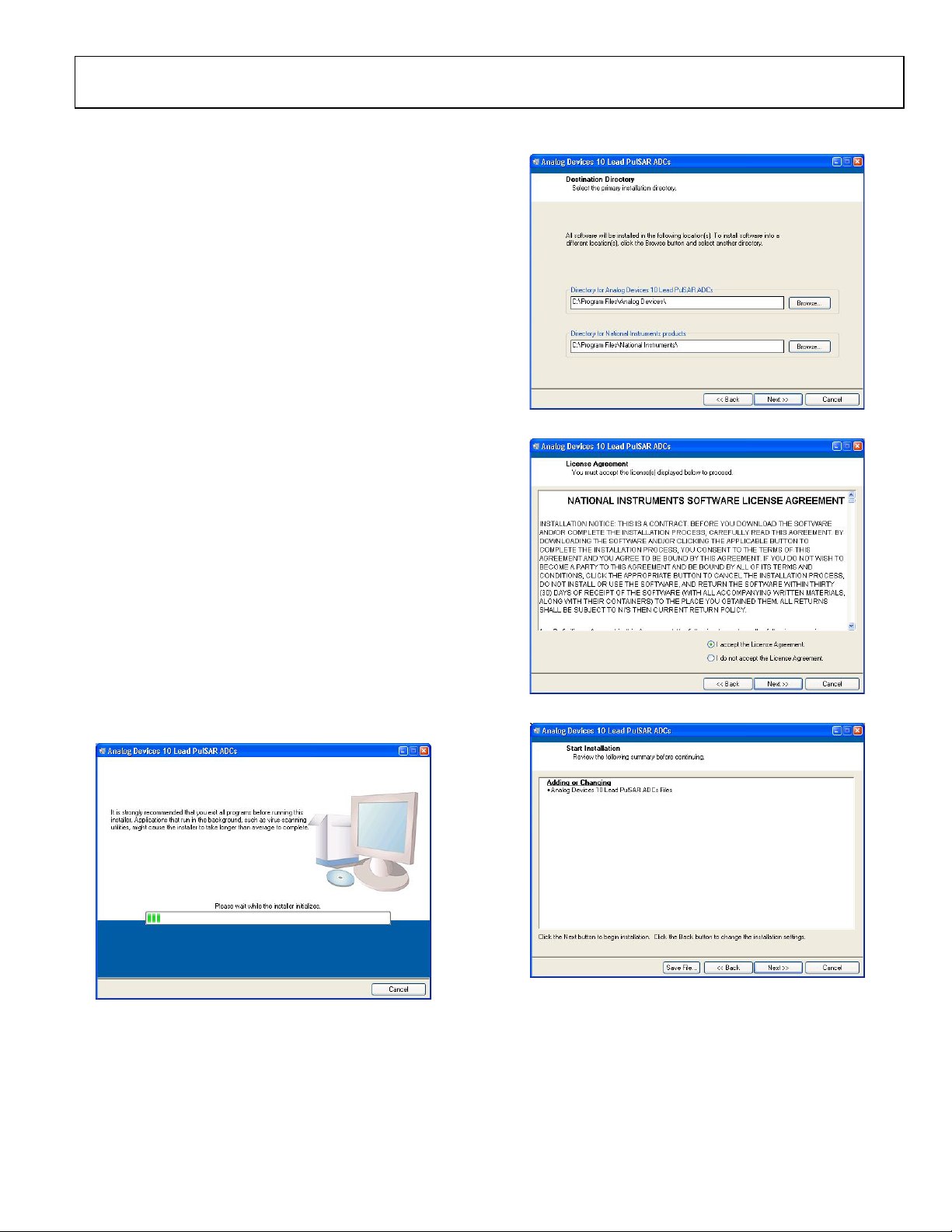
Figure 3. Choose Folder Location, Default Folder Shown
INSTALLATION STEPS
Proceed through the installation allowing the software and
drivers to be placed in the appropriate locations. Only after the
software and drivers have been installed should you connect the
SDP board to the PC.
There are two parts to the software installation. First, the software
related to the evaluation board, as shown in Figure 2 to Figure 7.
Figure 2. Evaluation Board Software Installation Launches
Figure 4. Accept National Instruments Software License Agreement
Figure 5. Click Next >> to Install Software
Rev. 0 | Page 5 of 28
Page 6
UG-340 Evaluation Board User Guide
10322-006
10322-007
10322-008
10322-009
10322-010
10322-011
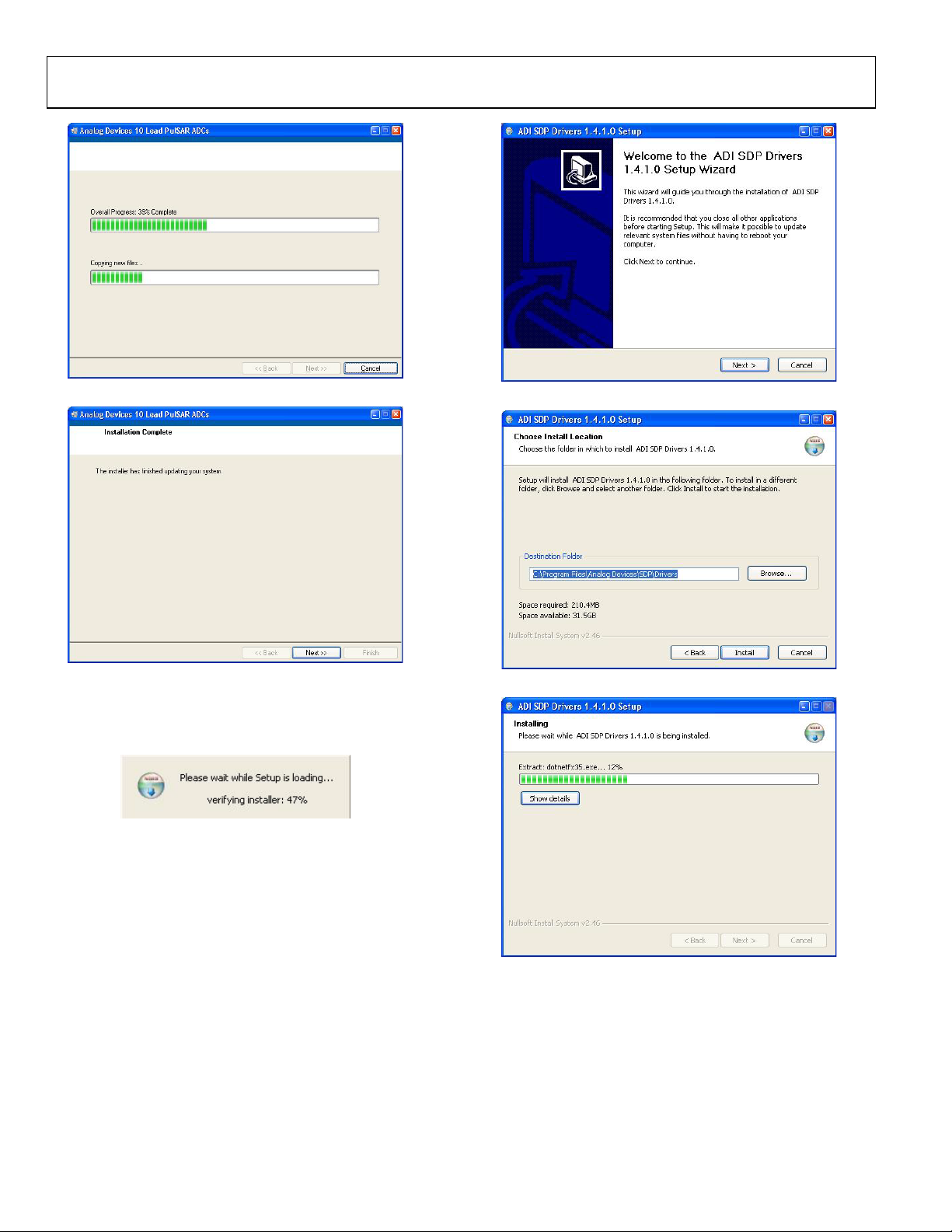
Figure 6. Bar Showing Installation Progress
Figure 7. Installation Complete, Click Next >> to Complete and Finish
The second part of the software installation is the drivers
related to the SDP board. These must be installed for the
evaluation board to function correctly. See Figure 8 to Figure 12.
Figure 8. Installation for SDP Starting
Figure 9. Click Next >> to Install the ADI SDP Drivers
Figure 10. Choose Install Location, Default Folder Shown
Figure 11. Installation in Progress
Rev. 0 | Page 6 of 28
Page 7
Evaluation Board User Guide UG-340
10322-013
10322-014
10322-015
10322-016
10322-017
RUNNING THE SOFTWARE WITH THE HARDWARE CONNECTED
To run the program,
1. Click Start > All Programs > Analog Devices > 10 Lead
PulSAR ADCs. To uninstall the program, click Start >
Control Panel > Add or Remove Programs > 10 Lead
PulSAR ADCs.
2. If the SDP board is not connected to the USB port when
the software is launched, a connectivity error displays (see
Figure 14). Simply connect the evaluation board to the
USB port of the PC, wait a few seconds, click Rescan, and
follow the instructions.
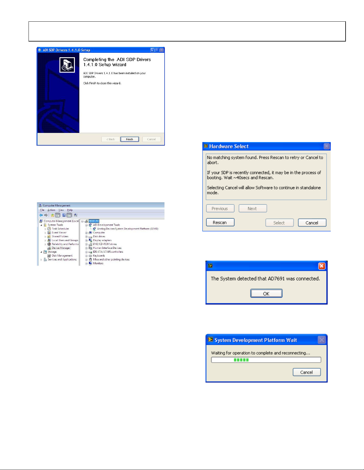
Figure 12. Click Finish to Complete Installation
When you first plug in the SDP board via the USB cable provided,
allow the new Found Hardware Wizard to run. You can check
that the drivers and the board are connected correctly by looking at
the Device Manager of the PC. The Analog Devices System
Development Platform (32MB) should appear under ADI
Development Tools.
Figure 13. Device Manager
BOARD OPERATION/CONNECTION SEQUENCE
The following is the board operation/connection sequence:
1. Connect SDP controller board to the evaluation board with
the J5 connector (screw into place as required). The
software is configured to find the evaluation board on
either connector of the SDP board.
2. Power board with appropriate supply as described in the
Power Supplies section.
3. Connect to PC with USB cable provided.
4. Launch software. Click Start > All Programs > Analog
Devices > 10 Lead PulSAR ADCs.
5. Apply signal source and capture data.
Figure 14. SDP Board Not Connected to the USB Port Pop-Up Window Error
3. When it finds the evaluation board, Figure 15 displays, and
then hit OK to continue.
Figure 15. Software Detects Evaluation Board
4. The software then connects to the board and displays what
is shown in Figure 16.
Figure 16. Software Connects to SDP Board
5. Once the board is correctly detected, the software panel
will open.
Rev. 0 | Page 7 of 28
Page 8
UG-340 Evaluation Board User Guide
10322-018
10322-019
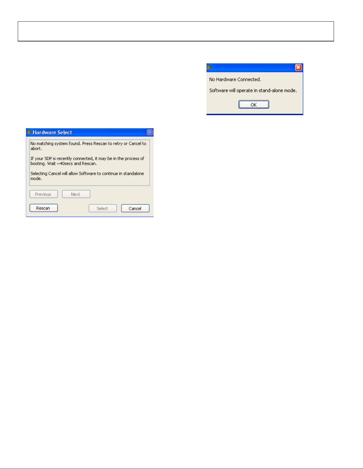
RUNNING THE SOFTWARE WITHOUT HARDWARE
The software can run in standalone mode when no evaluation
board hardware is connected to the USB port.
1. Click Start > All Programs > Analog Devices > 10 Lead
PulSAR ADCs.
2. The software automatically seeks to find the hardware
connected; therefore, when no hardware is connected, it
will pop up with a connectivity error (see Figure 17). If
user wishes to continue without hardware in standalone
mode, click Cancel.
3. The software will alert the user that no hardware is connected
and that the software will continue in standalone mode.
Figure 18. Software Indicates Operating in Standalone Mode
4. Within standalone/offline mode, the user can load example
files or previously saved files and analyze these files.
5. If the user decides to connect hardware at this point, he or
she must close the software and relaunch it to allow it to
search for the board again.
Figure 17. No Hardware Connected Pop-Up W indow Error
Rev. 0 | Page 8 of 28
Page 9
Evaluation Board User Guide UG-340
10322-020
2
3
4
5
6
7 8 9
10
1
10322-021
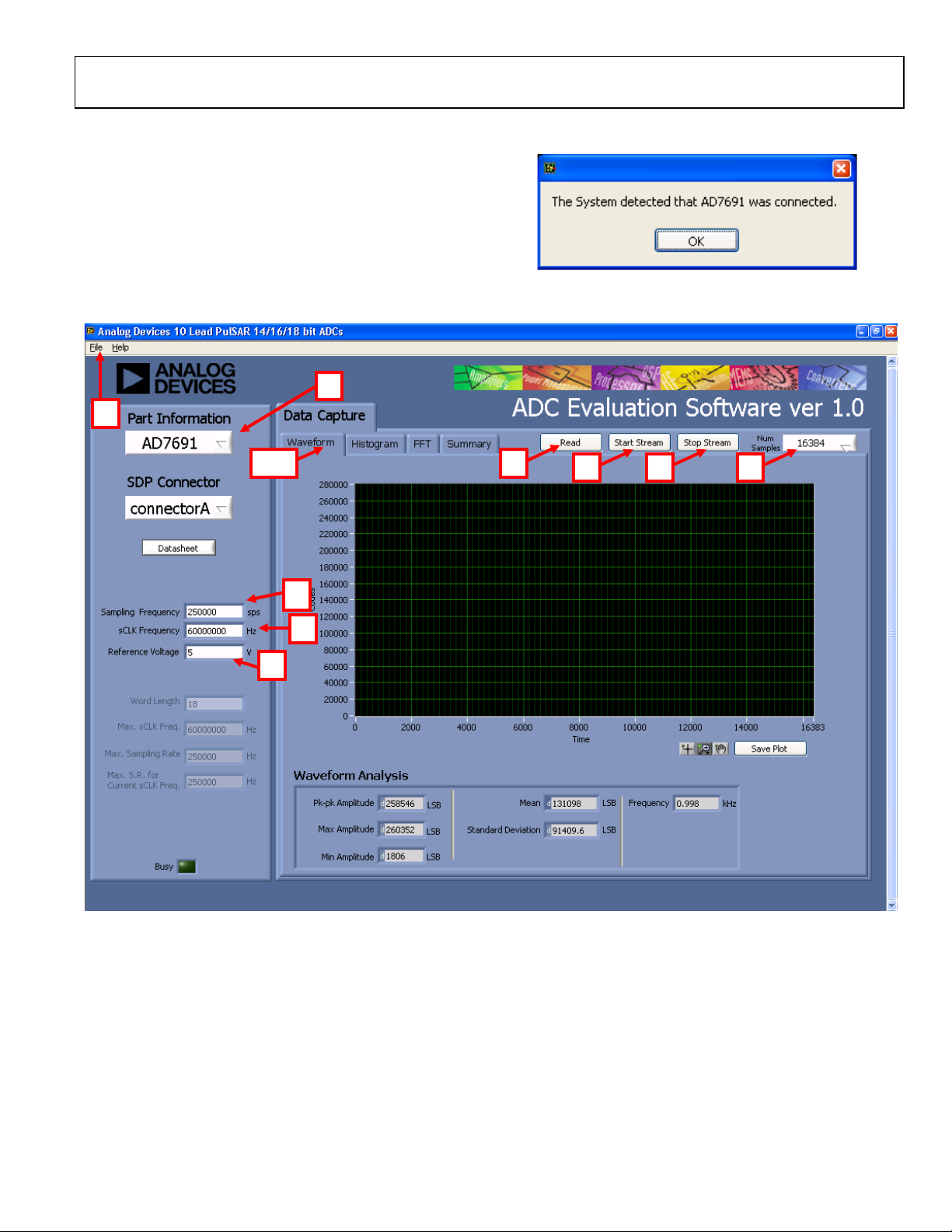
SOFTWARE OPERATION
When the software launches, the panel opens and the software
looks for the hardware connected to the PC. The software
detects the generic attached to the PC (see Figure 19). The
product panel then launches.
Figure 19. Software Detects AD7691
Figure 20. Setup Screen
Rev. 0 | Page 9 of 28
Page 10

UG-340 Evaluation Board User Guide
10322-022
DESCRIPTION OF USER PANEL
The following is the description of the user panel:
1. File menu with choice of
a. Load Data: load previously captured data
b. Save Data as .tsv: save captured data in tsv (tab
separated values) format for future analysis
c. Save Picture: use to save the current screen capture
d. Print
e. Exit
2. When hardware is connected to the USB port, the software
automatically detects which generic is connected and displays
it here. Without hardware, the software can be operated in
standalone mode for data analysis, and the part information
will note the part number pulled from the saved data file.
3. Sampling Frequency: The default sampling frequency will
match the maximum sample rate of the ADC connected to
the board. The user can adjust the sampling frequency;
however, there are limitations around the sample frequency
related to the SCLK frequency applied. The sample frequency
must be an integer divider of the SCLK frequency. In addition,
where unusable sample frequencies are input, the software
automatically adjusts the sample frequency accordingly.
Units can be entered, such as 10k for 10,000 Hz. Because
the maximum sample frequency possible is device dependent,
with some of the ADCs capable of operating up to 250 kSPS,
while others can go to 1.3 MSPS, the software will match
the particular ADC ability. If the user enters a value larger
than the ability of the existing device, the software will
indicate this and revert to the maximum sample frequency.
4. sCLK Frequency: The default SCLK frequency is set to
60 MHz, which is the maximum allowable from the SDP.
The SCLK is applied to the ADC SCK pin. The SDP board
limits the SCLK frequency, nominal values for correct
operation are 60 MHz, 30 MHz, and 20 MHz. Where the
user adjusts the SCLK/sample rate to values that are not
supported by the SDP clock or the ADC sample rate, the
software overrides by adjusting values accordingly and
identify this to the user (see Figure 21). The SCLK frequency
will be rounded down.
Figure 21. Software Overwritten User Settings to a Sample Rate/sCLK Rate
Suitable for SDP Data Transfer
5. External Reference Voltage. By default, this reference is 5 V
(ADR435 on-board reference). The minimum/maximum
voltage calculations are based on this reference voltage. If
user changes the reference voltage, he or she must change
this input accordingly.
6. Click Read to perform a single capture.
7. Click Start Stream to perform a continuous capture from
the ADC.
8. Click Stop Stream to stop streaming data.
9. Select the number of samples (Num Samples) to analyze,
when running continuously, this number will be limited to
65,536 samples.
10. There are four tabs available that display the data in
different formats:
a. Wa vefor m
b. Histogram
c. FFT
d. Summary
To exit the software, go to File > Exit.
Within any of the chart panels, the tools shown in Tabl e 4 allow
for user control of the different chart displays.
Table 4.
Symbol Description
This tool is used to control the cursor, if present.
This tool is used to zoom in and out.
This tool is used for panning.
To save the plot, click Save Plot.
Rev. 0 | Page 10 of 28
Page 11

Evaluation Board User Guide UG-340
1
10322-023
WAVEFORM CAPTURE
Figure 22 illustrates the waveform capture. The input signal is a
1 kHz sine wave.
The waveform analysis reports the amplitudes recorded from
the captured signal in addition to the frequency of the signal tone.
Figure 22. Waveform Tab
Rev. 0 | Page 11 of 28
Page 12

UG-340 Evaluation Board User Guide
1
10322-024
AC TESTING—HISTOGRAM
The ac testing histogram tests the ADC for the code distribution
for the ac input, computes the mean and standard deviation, or
transition noise, of the converter, and displays the results. Raw
data is captured and passed to the PC for statistical computations.
To perform a histogram test, select Histogram and click Start
Stream. Note that an ac histogram needs a quality signal source
applied to the input J6/J10 connectors. Figure 23 shows the
histogram for a 1 kHz sine wave applied to the ADC input.
Figure 23 shows the histogram results for the signal applied. It
also illustrates the different measured values for the data
captured (see Number 1 within Figure 23).
Figure 23. Histogram Tab, Histogram Captured for Sine Wave
Rev. 0 | Page 12 of 28
Page 13

Evaluation Board User Guide UG-340
1
2 3
10322-025
DC TESTING—HISTOGRAM
More commonly, the histogram is used for dc testing where the
user tests the ADC for the code distribution for dc input,
computes the mean and standard deviation, or transition noise,
of the converter, and displays the results. Raw data is captured
and passed to the PC for statistical computations. To perform a
histogram test, select Histogram and click Start Stream. Note
that a histogram test can be performed without an external
source because the evaluation board has a buffered V
REF
/2
source at the ADC input. To test other dc values, apply a source
to the J6/J10 inputs. It may be required to filter the signal to
make the dc source noise compatible with that of the ADC.
AC TESTING—FFT CAPTURE
This tests the traditional ac characteristics of the converter and
displays a fast fourier transform (FFT) of the result. As in the
histogram test, raw data is captured and passed to the PC where
the FFT is performed displaying signal-to-noise ratio (SNR),
signal-to-noise-and-distortion ratio (SINAD), total harmonic
distortion (THD), and spurious-free dynamic range (SFDR).
The data can also be displayed in the time domain. To perform
an ac test, apply a sinusoidal signal to the evaluation board at
the SMA inputs, J6/J10. Low distortion, better than 100 dB, is
required to allow true evaluation of the part. One possibility is
to filter the input signal from the ac source. A band-pass filter
can be used, and its center frequency must match the test
frequency of interest. Furthermore, if using a low frequency
band-pass filter when the full-scale input range is more than a
few V p-p, use the on-board amplifiers to amplify the signal,
thus preventing the filter from distorting the input signal.
Figure 24 displays the histogram of the captured data that
includes the following:
• The spectrum information
• The fundamental frequency and amplitude in addition to
the second-to-fifth harmonics
• The performance data (SNR, dynamic range, THD,
SINAD, and noise performance)
Figure 24. FFT Tab
Rev. 0 | Page 13 of 28
Page 14

UG-340 Evaluation Board User Guide
10322-026
SUMMARY TAB
Summary captures all the display information and provides them in one panel with a synopsis of the information including key
performance parameters, such as SNR and THD.
Figure 25. Summary Tab, Shows All Captured Windows
Rev. 0 | Page 14 of 28
Page 15

Evaluation Board User Guide UG-340
10322-027
SAVE FILE
The software can save the current captured data for later
analysis, and the file format is .tsv (tab separated values).
User is prompted with a Choose or Enter Path of File box (see
Figure 26) and should save to an appropriate folder location.
LOAD FILE
User is prompted with a Load File box. User may have to navigate
to find these example files. The default location for the example
files is C:\Program Files\Analog Devices\10 Lead PulSAR
ADCs\examples.
Figure 26. Save Dialog Box
Rev. 0 | Page 15 of 28
Page 16

UG-340 Evaluation Board User Guide
10322-128
EVALUATION BOARD SCHEMATICS
Figure 27. Evaluation Board Schematic
Rev. 0 | Page 16 of 28
Page 17

Evaluation Board User Guide UG-340
10322-129
10322-130
Figure 28. Voltage Reference and Common-Mo de Buffer
Figure 29. Secondary Power Connector for Bench Supply Purposes
Rev. 0 | Page 17 of 28
Page 18

UG-340 Evaluation Board User Guide
10322-131
Figure 30. On-Board Amplifier Power Supply, +7.5/−2.5 V
Rev. 0 | Page 18 of 28
Page 19

Evaluation Board User Guide UG-340
10322-132
10322-133
Figure 31. SDP Power Supply
Figure 32. ADC/V
Power Supply
DRIVE
Rev. 0 | Page 19 of 28
Page 20

UG-340 Evaluation Board User Guide
10322-134
Figure 33. SDP Connector and Glue Logic
Rev. 0 | Page 20 of 28
Page 21

Evaluation Board User Guide UG-340
10322-135
Figure 34. Header Connectors, Optional Connectors for Possible Add-On Boards
Rev. 0 | Page 21 of 28
Page 22

UG-340 Evaluation Board User Guide
10322-136
10322-137
Figure 35. Silkscreen, Top Layer
Figure 36. Evaluation Board Layer 1
Rev. 0 | Page 22 of 28
Page 23

Evaluation Board User Guide UG-340
10322-138
10322-139
Figure 37. Evaluation Board Layer 2
Figure 38. Evaluation Board Layer 3
Rev. 0 | Page 23 of 28
Page 24

UG-340 Evaluation Board User Guide
10322-140
Figure 39. Evaluation Board Layer 4
Rev. 0 | Page 24 of 28
Page 25

Evaluation Board User Guide UG-340
TROUBLESHOOTING
SOFTWARE
To troubleshoot the software, take the following steps:
1. Always install the software prior to connecting the hardware
to the PC.
2. Always allow the install to fully complete (the software is a
2-part install, the ADC software and the SDP drivers). This
may require a restart.
3. When the user first plugs in the SDP board via the USB cable
provided, allow the new Found Hardware Wizard to run.
This may take a little time but allow this to happen prior to
starting the software.
4. Where the board does not appear to be functioning, ensure
that the ADC evaluation board is connected to the SDP board
and that the board is being recognized in the Device
Manager, as shown in Figure 13.
5. If connected to a slower USB port where the SDP cannot read
as quickly as it needs to, this may result in a timeout error.
In this case, it is advised not to read continuously, or
alternatively, lower the number of samples taken.
6. When reading continuously from the ADC, the number of
samples is always limited to 65,536.
HARDWARE
To troubleshoot the hardware, take the following steps:
1. If the software does not read any data back, do the
following:
a. Check that the power is applied within the power
ranges described in the Power Supplies section.
b. Using a voltmeter, measure the voltage present at the
positive terminal of C3 (it should be 7.5 V) and C14
(it should be −2.5 V) and measure the voltage at the
positive terminal of C11 (it should be 5 V). The SDP
board, LED1, should be light.
c. Launch the software and read the data. If nothing
happens, exit the software.
d. Power down the board and relaunch the software.
e. If no success, confirm that the ADC evaluation board
is connected to the SDP board and that the board is
being recognized in the Device Manager, as shown in
Figure 13.
2. When the user is working with the software in standalone/
offline mode (no hardware connected) and they later
choose to connect hardware, they will need to close and
relaunch the software.
Rev. 0 | Page 25 of 28
Page 26

UG-340 Evaluation Board User Guide
AD7942BRMZ
EVAL-AD7942SDZ
250 kSPS
14
10-Lead MSOP
AD7984BRMZ
EVAL-AD7984SDZ
1.33 MSPS
18
10-Lead MSOP
Resource
Description
PRODUCTS ON THIS EVALUATION BOARD
Table 5.
Product Ordering Model Sample Rate Resolution (Bit) Package Used on Evaluation Board
AD7685BRMZ EVAL-AD7685SDZ 250 kSPS 16 10-Lead MSOP
AD7686BRMZ EVAL-AD7686SDZ 500 kSPS 16 10-Lead MSOP
AD7687BRMZ EVAL-AD7687SDZ 250 kSPS 16 10-Lead MSOP
AD7688BRMZ EVAL-AD7688SDZ 500 kSPS 16 10-Lead MSOP
AD7690BRMZ EVAL-AD7690SDZ 400 kSPS 18 10-Lead MSOP
AD7691BRMZ EVAL-AD7691SDZ 250 kSPS 18 10-Lead MSOP
AD7693BRMZ EVAL-AD7693SDZ 500 kSPS 16 10-Lead MSOP
AD7946BRMZ EVAL-AD7946SDZ 500 kSPS 14 10-Lead MSOP
AD7980BRMZ EVAL-AD7980SDZ 1 MSPS 16 10-Lead MSOP
AD7982BRMZ EVAL-AD7982SDZ 1 MSPS 18 10-Lead MSOP
AD7983BRMZ EVAL-AD7983SDZ 1.33 MSPS 16 10-Lead MSOP
AD7988-5BRMZ EVAL-AD7988-5SDZ 500 kSPS 16 10-Lead MSOP
RELATED LINKS
AD8031 Product Page, AD8031, 2.7 V, 800 µA, 80 MHz Rail-to-Rail I/O Single Amplifier
ADA4841-1 Product Page, ADA4841-1, Low Power, Low Noise and Distortion, Rail-to-Rail Output Amplifier
ADR435 Product Page, ADR435, Ultralow Noise XFET® Voltage References with Current Sink and Source Capability
ADP7102 Product Page, ADP7102, 20 V, 300 mA, Low Noise, CMOS LDO
ADP7104 Product Page, ADP7104, 20 V, 500 mA, Low Noise, CMOS LDO
ADP2301 Product Page, ADP2301, 1.2 A, 20 V, 1.4 MHz Nonsynchronous Step-Down Switching Regulator
EVAL-SDP-CB1Z Product Page, System Demonstration Platform (SDP)
AN-931 Application Note, Understanding PulSAR ADC Support Circuitry
Rev. 0 | Page 26 of 28
Page 27

Evaluation Board User Guide UG-340
NOTES
Rev. 0 | Page 27 of 28
Page 28

UG-340 Evaluation Board User Guide
neer chips on the Evaluation Board. Customer shall inform ADI of any
NOTES
ESD Caution
ESD (electrostatic discharge) sensitive device. Charged devices and circuit boards can discharge without detection. Although this product features patented or proprietary protection
circuitry, damage may occur on devices subjected to high e nergy ESD. Therefore, proper ESD precaution s should be taken to avoid per forma nce degra dation or loss of functionality.
Legal Terms and Conditions
By using the evaluation board discussed herein (together with any tools, components documentation or support materials, the “Evaluation Board”), you are agreeing to be bound by the terms a nd conditions
set forth below (“Agreement”) unless you have purchased the Evaluation Board, in which case the Analog Devices Standard Terms and Conditions of Sale shall govern. Do not use the Evaluation Board until you
have read and agreed to the Agreement . Your use of the Evaluation Board shall signify your acceptance of the Agreement. This Agreement is made by and between you (“Customer”) and Analog Devices, Inc.
(“ADI”), with its principal place of business at One Technology Way, Norwood, MA 02062, USA. Subject to the terms and conditions of the Agreement, ADI hereby grants to Customer a free, limited, personal,
temporary, non-exclusive, non-sublicensable, non-transferable license to use the Evaluation Board FOR EVALUATION PURPOSES ONLY. Customer understands and agrees that the Evaluatio n Board is provided
for the sole and exclusive purpose referenced above, and agrees not to use the Evaluation Board for any other purpose. Further more, the license granted is expressly made subject to the following additional
limitations: Customer shall not (i) rent, lease, display, sell, transfer, assign, sublicense, or distribute the Evaluation Board; and (ii) permit any Third Party to access the Evaluation Board. As used herein, the term
“Third Party” includes any entity other than ADI, Customer, their employees, affiliates and in-house consultants. The Evaluation Board is NOT sold to Customer; all rights not expressly granted herein, including
ownership of the Evaluation Board, are reserved by ADI. CONFIDENTIALITY. This Agreement and the Evaluation Board shall all be consi dered t he confidenti al and proprietary information of ADI. Customer may
not disclose or transfer any portion of the Evaluation Board to any other party for any reason. Upon discontinuation of use of the Evaluation Board or termination of this Agreement, Customer agrees to
promptly return the Evaluation Board to ADI. ADDITIONAL RESTRICTIONS. Customer may not disassemble, decompile or reverse engi
occurred damages or any modifications or alterations it makes to the Evaluation Board, including but not limited to soldering or any other activity that affects the material content of the Evaluation Board.
Modifications to the Evaluation Board must comply with applicable law, including but no t limited to the RoHS Directive. TERMINATION. ADI may terminate this Agreement at any time upon giving written notice
to Customer. Customer agrees to return to ADI the Evaluation Board at that time. LIMITATION OF LIABILITY. THE EVALUATION BOARD PROVIDED HEREUNDER IS PROVIDED “AS IS” AND ADI MAKES NO
WARRANTIES OR REPRES ENTATIONS OF ANY KIND WITH RESPECT TO IT. ADI SPECIFICAL LY DISC LAIMS ANY REPRESENTATIONS, ENDORSEMENTS, GUA RANTEES, OR WARRANT IES, EXPRESS OR IMPLIED, RELATED
TO THE EVALUATION BOARD INCLUDING, BUT NOT LIMITED TO, THE IMPLIED WARRANTY OF MERCHANTABILITY, TITLE, FITNESS FOR A PARTICULAR PURPOSE OR NONINFRINGEMENT OF INTELLECTUAL
PROPERTY RIGHTS. IN NO EVENT WILL ADI AND ITS LICENSORS BE LIABLE FOR ANY INCIDENTAL, SPECIAL, INDIRECT, OR CONSEQUENTIAL DAMAGES RESULTING FROM CUSTOMER’S POSSESSION OR USE OF
THE EVALUAT ION BOARD, INCLUDING BUT NOT LIMI TED TO LOST PROFITS, DE LAY COSTS, LABOR COSTS OR LOSS OF GOODWI LL. ADI’S TOTAL LIA BILITY FROM AN Y AND ALL CAUSES S HALL BE LIMITED TO THE
AMOUNT OF ONE HUNDRED US DOLLARS ($100.00). EXPORT. Customer agrees that it will not directly or indirectly export the Evaluation Board to another country, and that it will comply with all applicable
United States federal laws and regulations relating to exports. GOVERNING LAW. This Agreement shall be governed by and construed in accordance with the substantive laws of the Commonwealth of
Massachusetts (excluding conflict of law rules). Any legal action regarding this Ag re ement will be heard in the state or federal courts having jurisdiction in Suffolk County, Massachusetts, and Customer hereby
submits to the personal jurisdiction and venue of such courts. The United Nations Convention on Contracts for the International Sale of Goods shall not ap ply to this Agreement and is expres sly disclaimed.
©2012 Analog Devices, Inc. All rights reserved. Trademarks and
registered trademarks are the property of their respective owners.
UG10322-0-5/12(0)
Rev. 0 | Page 28 of 28
 Loading...