

Page 1
Evaluation Board User Guide
UG-309
AD5546 AD8065
LDAC
REF
RS
MSB
I
OUT
WR
V
OUT
I-TO-V
10112-001
D0... D15
GPIO
PARALLEL
PORT
USB
EVAL-SDP-CB1Z
ADR01
REFERENCE
One Technology Way • P. O. Box 9106 • Norwood, MA 02062-9106, U.S.A. • Tel: 781.329.4700 • Fax: 781.461.3113 • www.analog.com
Evaluating the AD5546 Current Output/Serial Input DACs
FEATURES
Full-featured evaluation board for the AD5546
Graphic user interface software for board control and data
analysis
Connector to E VAL-SDP-CB1Z system demonstration
platform board
Various power supply options
APPLICATIONS
Automatic test equipment
Instrumentation
Digitally controlled calibration
Digital waveform generation
GENERAL DESCRIPTION
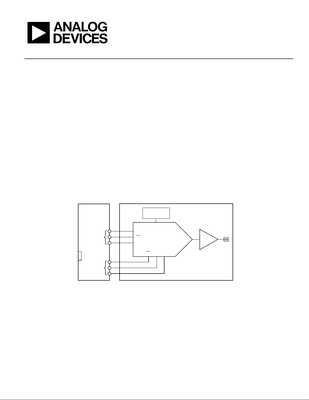
The AD5546 is a precision 16-bit, multiplying, low power,
current output, parallel input digital-to-analog converter (DAC).
FUNCTIONAL BLOCK DIAGRAM
It operates from a single 2.7 V to 5.5 V supply with ±10 V
multiplying references for four-quadrant outputs. Built-in
four-quadrant resistors facilitate the resistance matching and
temperature tracking that minimize the number of components
needed for multiquadrant applications.
The applied external reference input voltage (V
the full-scale output current. The feedback resistor (R
fies the I-to-V conversion with an external buffer.
The AD5546 is packaged in compact 28-lead TSSOP packages
with operating temperatures from –40°C to +125°C.
The E VA L -AD5546SDZ is used in conjunction with the E VA L -
SDP-CB1Z system demonstration platform (SDP) board available
from Analog Devices, Inc., which is purchased separately from
the evaluation board. The USB-to-SPI communication to the DAC
is completed using this Blackfin®-based demonstration board.
) determines
REF
) simpli-
FB
PLEASE SEE THE LAST PAGE FOR AN IMPORTANT
WARNING AND LEGAL TERMS AND CONDITIONS.
Figure 1.
Rev. A | Page 1 of 12
Page 2

UG-309 Evaluation Board User Guide
TABLE OF CONTENTS
Features .............................................................................................. 1
Applications ....................................................................................... 1
General Description ......................................................................... 1
Functional Block Diagram .............................................................. 1
Revision History ............................................................................... 2
Evaluation Board Software .............................................................. 3
Installing the Software ................................................................. 3
Running the Software .................................................................. 3
REVISION HISTORY
3/12—Rev. 0 to Rev. A
Added New Table 1; Renumbered Sequentially ........................... 4
Changes to the Example Section .................................................... 5
Replaced Evaluation Board Schematics and Artwork Section ... 6
11/11—Revision 0: Initial Version
Applications Provided .......................................................................4
Using the Evaluation Board Software .............................................5
Example ..........................................................................................5
Evaluation Board Schematics and Artwork ...................................6
Schematics ......................................................................................6
Evaluation Board Layout ..............................................................8
Related Links ......................................................................................9
Rev. A | Page 2 of 12
Page 3
Evaluation Board User Guide UG-309
10112-002
10112-003
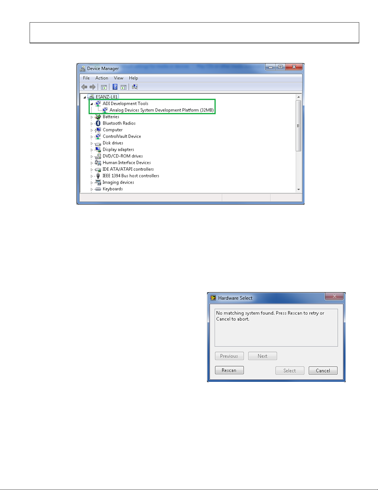
EVALUATION BOARD SOFTWARE
Figure 2. Device Manager Showing the SDP Board Connected
INSTALLING THE SOFTWARE
The EVAL-AD5546SDZ kit includes the software and drivers on a
CD. To install the software, follow these steps:
1. Install the software before connecting the SDP board to the
USB port of the PC.
2. Start the Windows® operating system and insert the EVAL-
AD5546SDZ CD.
3. Download the E VA L -AD5546SDZ LabVIEW™ software.
The correct driver for the SDP board, SDPDriversNET,
should download automatically after LabVIEW is
downloaded, supporting both 32- and 64-bit systems.
However, if the drivers do not download automatically, the
driver executable file can also be found in the Program
Files/Analog Devices folder. Follow the on-screen prompts
to install it.
4. After installation of the software and drivers is complete, plug
the EVA L -AD5546SDZ into the SDP board and the SDP
board into the PC using the USB cable included in the kit.
5. When the software detects the evaluation board, proceed
through any dialog boxes that appear to finalize the
installation (for example, Found New Hardware Wizard
and Install the Software Automatically).
RUNNING THE SOFTWARE
To run the evaluation board program, do the following:
1. Click Start/All Programs/Analog Devices/EVAL-
AD5546SDZ.
2. If the SDP board is not connected to the USB port when
the software is launched, a connectivity error displays (see
Figure 3). Simply connect the evaluation board to the USB
port of the PC, wait a few seconds, click Rescan, and follow
the instructions.
Figure 3. Connectivity Error
Rev. A | Page 3 of 12
Page 4

UG-309 Evaluation Board User Guide
APPLICATIONS PROVIDED
The EVAL-AD5546SDZ board provides the possibility of
configuring the DAC in two different unipolar two-quadrant
multiplying modes. Table 1 show how to select the desired
voltage reference. Table 2 shows the connections needed to
obtain these unipolar modes.
Table 1. Voltage Reference Selection
Link Connections
Link No. Position
LK1 IN
OUT
Func tion
Internal voltage reference ADR01
connected.
External voltage reference connected
to VREF (J3 SMB connector).
Table 2. Applications Provided
Link Connections
Link No. Position
LK2 A
LK3 A
Func tion
Unipolar two-quadrant multiplying
mode, V
LK4 In
LK2 B
LK3 B
Unipolar two-quadrant multiplying
mode, V
LK4 Out
= 0 V to −V
OUT
= 0 V to + V
OUT
REF
REF
Rev. A | Page 4 of 12
Page 5

Evaluation Board User Guide UG-309
10112-004
V2.5
536,65
384,16
10
536,65
−=×−=×−=DVV
REF
OUT
V5
536,65
768,32
10
536,65
−=×−=×−=DVV
REF
OUT
USING THE EVALUATION BOARD SOFTWARE
When the software is launched, the main window appears (see
Figure 4).
EXAMPLE
Using the internal voltage reference in the unipolar twoquadrant multiplying mode (V
MSB, and
RS
tied high, specify quarter scale (0x4000 or 16,384
decimal) in the Input Data box and click Wr ite DAC. The
expected output obtained is
RS
is tied low, with MSB tied high, a reset takes place in
If
the part, changing the output to half scale (0x8000 or 32,768
decimal).
= 0 V to −V
OUT
), with LDAC,
REF
Figure 4. Main Window
The desired data loads and updates the DAC’s output when
LDAC is brought high.
The reset button, /RS, updates all channel outputs to zero scale
or midscale when MSB is pulled low or high.
Rev. A | Page 5 of 12
Page 6

UG-309 Evaluation Board User Guide
10112-005
EVALUATION BOARD SCHEMATICS AND ARTWORK
SCHEMATICS
Figure 5. EVAL-AD5546SDZ Schematic, SDP Connector
Rev. A | Page 6 of 12
Page 7

Evaluation Board User Guide UG-309
10112-006
Figure 6. EVAL-AD5546SDZ Schematic, DAC
Rev. A | Page 7 of 12
Page 8

UG-309 Evaluation Board User Guide
10112-007
10112-008
EVALUATION BOARD LAYOUT
Figure 7. Silkscreen
Figure 8. Component Side
Rev. A | Page 8 of 12
Page 9

Evaluation Board User Guide UG-309
10112-009
Figure 9. Solder Side
RELATED LINKS
Resource Description
AD5546 Product Page, AD5546 Current-Output Parallel-Input, 16-Bit Digital-toAnalog-Converter
ADR01 Product Page, ADR01 Ultracompact, Precision 10.0 V Voltage Reference
AD8065 Product Page, AD8065: High Performance, 145 MHz FastFET™ Op Amp
EVAL-SDP-CB1Z Product Page, SDP-B: System Demonstration Platform—Blackfin
Rev. A | Page 9 of 12
Page 10

UG-309 Evaluation Board User Guide
NOTES
Rev. A | Page 10 of 12
Page 11

Evaluation Board User Guide UG-309
NOTES
Rev. A | Page 11 of 12
Page 12

UG-309 Evaluation Board User Guide
ment is made by and between you (“Customer”) and Analog Devices, Inc. (“ADI”),
NOTES
ESD Caution
ESD (electrostatic discharge) sensitive device. Charged devices and circuit boards can discharge without detection. Although this product features patented or proprietary protection
circuitry, damage may occur on devices subjected to high e nergy ESD. Therefore, proper ESD precaution s should be taken to avoid per forma nce degra dation or loss of functionality.
Legal Terms and Conditions
By using the evaluation board discussed herein (together with any tools, components documentation or support materials, the “Evaluation Board”), you are agreeing to b e bound by the terms an d conditions set
forth below (“Agreement”) unless you have purchased the Evaluation Board, in which case the Analog Devices Standard Terms and Conditions of Sale shall govern. Do not use the Evaluation Board until you have
read and agreed to the Agreement. Your use of the Evaluation Board shall signify your acceptance of the Agreement. This Agree
with its principal place of business at One Technology Way, Norwood, MA 02062, USA. Subject to the terms and conditions of the Agreement, A DI hereby grants to Customer a free, limited, personal, temporary,
non-exclusive, non-sublicensable, non-transferable license to use the Evaluation Board FOR EVALUATION PURPOSES ONLY. Customer understands and agrees that the Evaluation Board is provided for the sole and
exclusive purpos e referenced above, and agrees not to use the Evaluati on Board for any other purpose. Furthermo re, th e license granted is expressly made subject to the following additional limitations: Customer
shall not (i) rent, lease, display, sell, transfer, assign, sublicense, or distribute the Evaluation Board; and (ii) permit any Third Party to access the Evaluation Board. As used herein, the term “Third Party” includes any
entity other than ADI, Customer, their employees, affiliates and in-house consultants. The Evaluation Board is NOT sold to Customer; all rights not expressly granted herein, including ownership of the Evaluation
Board, are reser ved by ADI. CONFIDENTIALITY. This Agreement and the Evaluation Board shall all be considered the confidential and proprietary information of ADI. Customer may not disclose or transfer any
portion of the Evaluation Board to any other party for any reason. Upon discontinuation of use of the Evaluation Board or termination of this Agreement, Cu stomer agrees to promptly return the Evaluation Board
to ADI. ADDITIONAL RESTRICTIONS. Customer may not disassemble, decompile or reverse engineer chips on the Evaluation Board. Customer shall inform ADI of any occurred damages or any modifications or
alterations it m akes to the Evaluation Board, including but not limited to soldering or any other activity that affects the material content of the Evaluation Board. Modifications to t he Evaluati on Board must comply
with applicable law, including but not limited to the RoHS Directive. TERMINATION. ADI may terminate this Agreement at any time upon giving written notice to Customer. Customer agrees to return to ADI the
Evaluation Board at that time. LIMITATION OF LIABILITY. THE EVALUATION BOARD PROVIDED HEREUNDER IS PROVIDED “AS IS” AND ADI MAKES NO WARRANTIES OR REPRESENTATIONS OF ANY KIND WITH
RESPECT TO IT. ADI SPECIFICALLY DISCLAIMS ANY REPRESENTATIONS, ENDORSEMENTS, GUARANTEES, OR WARRANTIES, EXPRESS OR IMPLIED, RELATED TO THE EVALUATION BOARD INCLUDING, BUT NOT
LIMITED TO, THE IMPLIED WARRANTY OF MERCHANTABILITY, TITLE, FITNESS FOR A PARTICULAR PURPOSE OR NONINFRINGEMENT OF INTELLECTUAL PROPERTY RIGHTS. IN NO EVENT WILL ADI AND ITS
LICENSORS BE LIABLE FOR ANY INCIDENTAL, SPECIAL, INDIRECT, OR CONSEQUENTIAL DAMAGES RESULTING FROM CUSTOMER’S POSSESSION OR USE OF THE EVALUAT ION BOARD, INCLUDING BUT NOT LI MITED
TO LOST PROFITS, DELAY COSTS, LABOR COSTS OR LOSS OF GOODWILL. ADI’S TOTAL LIABILITY FROM ANY AND ALL CAUSES SHALL BE LIMITED TO THE AMOUNT OF ONE HUNDRED US DOLLARS ($1 00.00).
EXPORT. Customer agrees that it will not directly or indirectly export the Evaluation Board to another country, and that it will comply with all applicable United States federal laws and regulations relating to
exports. GO VERNING LAW. This Ag ree ment shall be governed by an d construed in accordance with the substantive laws of the Commonwealth of Massachusetts (excluding conflict of law rules). Any legal action
regarding this Agreement will be heard in the state or federal courts having jurisdiction in Suffolk County, Massachusett s, and Customer hereb y submits to the per sonal jurisdiction and venue of such courts. The
United Nations Conventio n on Contracts for the International Sale of Goods shall not appl y to this Agreement an d is expressly disclai med.
©2011–2012 Analog Devices, Inc. All rights reserved. Trademarks and
registered trademarks are the property of their respective owners.
UG10112-0-3/12(A)
Rev. A | Page 12 of 12
 Loading...