

Page 1
Evaluation Board User Guide
UG-165
One Technology Way • P. O . Box 9106 • Norwood, MA 02062-9106, U.S.A. • Tel : 781.329.4700 • Fax : 781.461.3113 • www.analog.com
Evaluation Board for Integer-N PLL Frequency Synthesizer
FEATURES
Self-contained board including synthesizer, VCO, and loop
filter (1 GHz to 1.7 GHz)
Designed for 1 MHz PFD frequency and 50 kHz loop
bandwidth
Accompanying software allows complete control of
synthesizer functions from a PC
Battery operated: choice of 3 V or 5 V supplies
V
supply must be externally driven
P
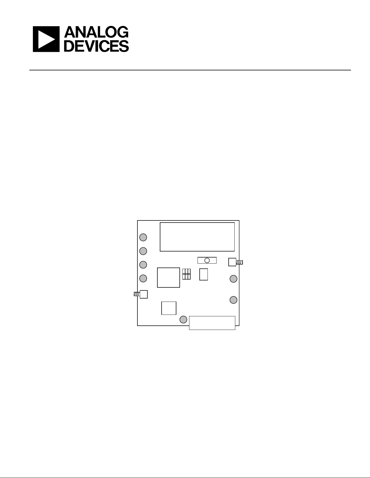
BLOCK DIAGRAM
GENERAL DESCRIPTION
This board is designed to allow the user to evaluate the
performance of the ADF4113HV frequency synthesizer for
phase locked loops (PLLs). The block diagram of the board is
shown in Figure 1. It contains the ADF4113HV synthesizer, a
PC connector, SMA connectors for the power supplies, and an
RF output. There is also a low-pass loop filter (50 kHz) and a
VCO (Sirenza VCO790-1500T) on board. The evaluation board
is set up for a 1 MHz PFD comparison frequency. The reference
frequency is provided by a 10 MHz TCXO. A cable is included
with the board to connect to a PC printer port. The V
supply must be driven externally.
The package also contains Windows® software to allow easy
programming of the synthesizer.
power
P
V
DD
V
VCO
TEST
SMA
SOCKET
VCO
TCXO
TEST
RF
OUT
9V BATTERY
POWER SWITCH
ON OFF
FILTER
ADF4113HV
EVAL-ADF411xEB1Z
REF
IN
Figure 1.
SMA
SOCKET
PC CONNECTOR
V
P
MUXOUT
CE
09150-001
PLEASE SEE THE LAST PAGE FOR AN IMPORTANT
WARNING AND LEGAL TERMS AND CONDITIONS.
Rev. 0 | Page 1 of 8
Page 2

UG-165 Evaluation Board User Guide
TABLE OF CONTENTS
Features.............................................................................................. 1
General Description ......................................................................... 1
Block Diagram .................................................................................. 1
Revision History ............................................................................... 2
Evaluation Board Hardware............................................................ 3
Overview........................................................................................ 3
REVISION HISTORY
6/11—Revision 0: Initial Version
Power Supplies...............................................................................3
Local Oscillator Components......................................................3
Evaluation Board Software...............................................................4
Evaluation Board Schematics and Artwork...................................5
Test Setup........................................................................................6
Rev. 0 | Page 2 of 8
Page 3
Evaluation Board User Guide UG-165
EVALUATION BOARD HARDWARE
OVERVIEW
The evaluation board is supplied with a cable for connecting to
the printer port of a PC. The board schematics are shown in
Figure 5 and Figure 6.
POWER SUPPLIES
The board is powered from a single 9 V battery, and an external
15 V source. The power supply circuitry allows the user to choose
3 V for the ADF4113HV V
supply. The default settings are 3 V for the ADF4113HV V
and 5 V for the VCO supply. The supply pin, V
externally via the SMA provided (J10) with 15 V.
It is very important to note that the ADF4113HV V
never exceed the ADF4113HV V
the device.
External power supplies can be used for the ADF4113HV V
and VCO power supplies. In this case, insert SMA connectors as
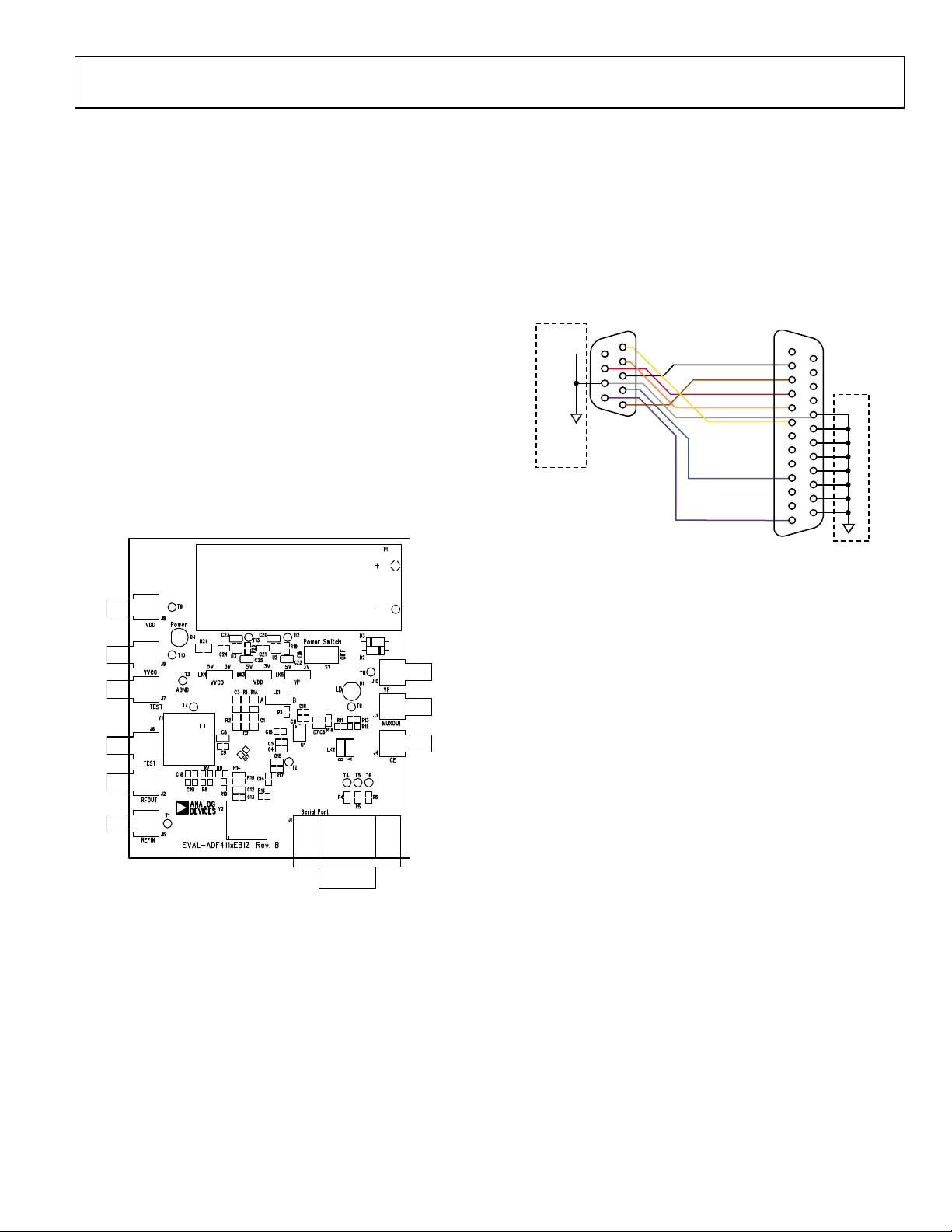
shown on the silkscreen (see Fi
ure 1).
(see Fig
and either 3 V or 5 V for the VCO
DD
, must be driven
P
should
DD
. This can cause damage to
P
gure 2) and the block diagram
DD
DD
LOCAL OSCILLATOR COMPONENTS
All components necessary for LO generation are on the board.
A 10 MHz TCXO from Fox provides the reference frequency.
The on-board loop filter is set up for a 640 μA charge pump
current and gives a loop bandwidth of 50 kHz. The VCO is
the VCO790-1500T from Sirenza. The output is available at
RF
through a standard SMA connector.
OUT
EVAL-ADF411x
EVAL-ADF421x
1
6
2
7
3
8
4
9
5
9-WAY
FEMALE D-TYPE
TO
ADF411x
ADF421x
EVALUATION
BOARD
Figure 3. PC Cable Diagram
BLACK-CLK
BROWN-DATA
ORANGE-CE
WHITE-GND
YELLOW
1
2
3
RED-LE
4
5
6
7
8
9
BLUE
10
11
12
PURPLE
13
25-WAY
MALE D-TYPE
PC PRINTER PORT
TO
14
15
16
17
18
19
20
21
22
23
24
25
PC
09150-003
09150-002
Figure 2. Evaluation Board Silkscreen
Rev. 0 | Page 3 of 8
Page 4

UG-165 Evaluation Board User Guide
EVALUATION BOARD SOFTWARE
The control software for the EVAL-ADF4113HVEBZ1 is on the
CD, which accompanies the board. Click on setup.exe to open
the install wizard, which guides you through the install process.
Simply follow the on-screen instructions. The software is
installed in a default directory: C:/Program Files/Analog
Devices/ADF4xxx. To run the software, double-click on
ADF_Revx_x.exe.
Before the Main Interface Page opens, the device window
appears, which prompts you to choose the device to be
evaluated. Select ADF4113HV and click OK. The Main
Interface Page window now opens (see Figure 4). To change the
VCO output frequency and/or channel spacing, click the RF
VCO Output Frequenc y text. The output frequency window
opens and you can change this value. The other values under
the RF Section can be changed in a similar manner. The window
should be set up as shown in Figure 4 for the ADF4113HV
evaluation board. Note that the charge pump current is set to
the maximum. To program the ADF4113HV, click the Resend
Data button and load the three registers.
9150-007
Figure 4. Software Front Panel
Rev. 0 | Page 4 of 8
Page 5

Evaluation Board User Guide UG-165
EVALUATION BOARD SCHEMATICS AND ARTWORK
09150-004
Figure 5. Evaluation Board Schematic (Page 1)
Rev. 0 | Page 5 of 8
Page 6

UG-165 Evaluation Board User Guide
09150-005
TEST SETUP
SPECTRUM ANALYZER
Figure 6. Evaluation Board Schematic (Page 2)
POWER SUPPLY
+15V
PC
9V BATTERY
POWER SWITCH
ON OFF
FILTER
VCO
ADF4113HV
SMA
RF
OUT
SOCKET
TCXO
EVAL-ADF411xEB1Z
PC CONNECTOR
REF
IN
SMA
SOCKET
V
P
MUXOUT
CE
09150-006
Figure 7. Test Setup
Rev. 0 | Page 6 of 8
Page 7

Evaluation Board User Guide UG-165
NOTES
Rev. 0 | Page 7 of 8
Page 8

UG-165 Evaluation Board User Guide
NOTES
ESD Caution
ESD (electrostatic discharge) sensitive device. Charged devices and circuit boards can discharge without detection. Although this product features patented or proprietary protection
circuitry, damage may occur on devices subjected to high energy ESD. Therefore, proper ESD precautions should be taken to avoid performance degradation or loss of functionality.
Legal Terms and Conditions
By using the evaluation board discussed herein (together with any tools, components documentation or support materials, the “Evaluation Board”), you are agreeing to be bound by the terms and conditions
set forth below (“Agreement”) unless you have purchased the Evaluation Board, in which case the Analog Devices Standard Terms and Conditions of Sale shall govern. Do not use the Evaluation Board until you
have read and agreed to the Agreement. Your use of the Evaluation Board shall signify your acceptance of the Agreement. This Agreement is made by and between you (“Customer”) and Analog Devices, Inc.
(“ADI”), with its principal place of business at One Technology Way, Norwood, MA 02062, USA. Subject to the terms and conditions of the Agreement, ADI hereby grants to Customer a free, limited, personal,
temporary, non-exclusive, non-sublicensable, non-transferable license to use the Evaluation Board FOR EVALUATION PURPOSES ONLY. Customer understands and agrees that the Evaluation Board is provided
for the sole and exclusive purpose referenced above, and agrees not to use the Evaluation Board for any other purpose. Furthermore, the license granted is expressly made subject to the following additional
limitations: Customer shall not (i) rent, lease, display, sell, transfer, assign, sublicense, or distribute the Evaluation Board; and (ii) permit any Third Party to access the Evaluation Board. As used herein, the term
“Third Party” includes any entity other than ADI, Customer, their employees, affiliates and in-house consultants. The Evaluation Board is NOT sold to Customer; all rights not expressly granted herein, including
ownership of the Evaluation Board, are reserved by ADI. CONFIDENTIALITY. This Agreement and the Evaluation Board shall all be considered the confidential and proprietary information of ADI. Customer may
not disclose or transfer any portion of the Evaluation Board to any other party for any reason. Upon discontinuation of use of the Evaluation Board or termination of this Agreement, Customer agrees to
promptly return the Evaluation Board to ADI. ADDITIONAL RESTRICTIONS. Customer may not disassemble, decompile or reverse engineer chips on the Evaluation Board. Customer shall inform ADI of any
occurred damages or any modifications or alterations it makes to the Evaluation Board, including but not limited to soldering or any other activity that affects the material content of the Evaluation Board.
Modifications to the Evaluation Board must comply with applicable law, including but not limited to the RoHS Directive. TERMINATION. ADI may terminate this Agreement at any time upon giving written notice
to Customer. Customer agrees to return to ADI the Evaluation Board at that time. LIMITATION OF LIABILITY. THE EVALUATION BOARD PROVIDED HEREUNDER IS PROVIDED “AS IS” AND ADI MAKES NO
WARRANTIES OR REPRESENTATIONS OF ANY KIND WITH RESPECT TO IT. ADI SPECIFICALLY DISCLAIMS ANY REPRESENTATIONS, ENDORSEMENTS, GUARANTEES, OR
TO THE EVALUATION BOARD INCLUDING, BUT NOT LIMITED TO, THE IMPLIED WARRANTY OF MERCHANTABILITY, TITLE, FITNESS FOR A PARTICULAR PURPOSE OR NONINFRINGEMENT OF INTELLECTUAL
PROPERTY RIGHTS. IN NO EVENT WILL ADI AND ITS LICENSORS BE LIABLE FOR ANY INCIDENTAL, SPECIAL, INDIRECT, OR CONSEQUENTIAL DAMAGES RESULTING FROM CUSTOMER’S POSSESSION OR USE OF
THE EVALUATION BOARD, INCLUDING BUT NOT LIMITED TO LOST PROFITS, DELAY COSTS, LABOR COSTS OR LOSS OF GOODWILL. ADI’S TOTAL LIABILITY FROM ANY AND ALL CAUSES SHALL BE LIMITED TO THE
AMOUNT OF ONE HUNDRED US DOLLARS ($100.00). EXPORT. Customer agrees that it will not directly or indirectly export the Evaluation Board to another country, and that it will comply with all applicable
United States federal laws and regulations relating to exports. GOVERNING LAW. This Agreement shall be governed by and construed in accordance with the substantive laws of the Commonwealth of
Massachusetts (excluding conflict of law rules). Any legal action regarding this Agreement will be heard in the state or federal courts having jurisdiction in Suffolk County, Massachusetts, and Customer hereby
submits to the pers onal jurisdiction and venu e of such courts. The United Nations Conventi on on Contracts for the Internation al Sale of Goods shall not apply to this Agreement and is expressly disclaimed.
©2011 Analog Devices, Inc. All rights reserved. Trademarks and
registered trademarks are the property of their respective owners.
UG09150-0-6/11(0)
Rev. 0 | Page 8 of 8
WARRANTIES, EXPRESS OR IMPLIED, RELATED
 Loading...