

Page 1

Evaluation Board User Guide
UG-030
One Technology Way • P. O . Box 9106 • Norwood, MA 02062-9106, U.S.A. • Tel : 781.329.4700 • Fax : 781.461.3113 • www.analog.com
Using the ADAU1381 Sound Engine
INTRODUCTION
This user guide explains the signal flow and parameter settings
for the ADAU1381 sound engine. The ADAU1381 is ideal for
low power portable applications, such as digital camera audio.
During the recording or playing back of audio, the sound
engine provides many signal processing features to improve
audio quality.
DIGITAL CAMERA SYSTEM OVERVIEW
Although the ADAU1381 is flexible enough to be used in
several types of portable audio applications, its design specifically
targets digital camera systems. The sound processing engine
was, therefore, designed especially with such a system in mind.
In general, digital cameras use audio processing when recording
or playing back video. When recording, one or more microphones
mounted in the camera or connected externally capture the
audio data, which is then stored in the memory along with the
video data. During playback or review mode, the audio data is
retrieved from memory and played back through a speaker
mounted in the camera or through a jack for headphones or
other external connections.
In record mode, the source is an audio transducer (microphone)
and the target is memory. In playback mode, the source is
memory and the target is an audio transducer (speaker). In
both modes, the sound engine is positioned between the source
and target, processing the signal to improve audio quality.
Because the required audio processing differs depending on the
operating mode of the camera, several audio processing modes
have been implemented in the sound engine of the ADAU1381.
SOUND ENGINE SIGNAL FLOW BLOCK DIAGRAM
AUDIO MODE
AUDIO PROCESSING MODES
Record Mode
Record mode takes audio input from a microphone. Wind noise
reduction is applied to remove unwanted noise from the signal
and improve audio clarity. The enhanced stereo capture algorithm
provides improved stereo separation when microphones are
spaced close together. The six-band equalizer can be programmed
to augment bands of interest and filter out unwanted frequencies.
The dual-band dynamics processor acts as an automatic level
control, compensating for fluctuating input signal levels. The
processed signal is output to a digital storage medium.
Two record modes exist: Record A (REC A) and Record B (REC B).
The only differences between the two modes are the six-band
equalizer and the dual-band dynamics processor settings. The
two record modes allow for different audio recording profiles,
such as voice or music. The recording profile can be changed by
a single write to the RAM parameter.
Playback Mode
Playback mode takes audio input from the digital storage. The sixband equalizer is used for frequency compensation with the output
speaker or headphones. The dual-band dynamics processor acts
as a compressor, allowing for suitable playback levels even in
noisy environments. The playback output includes a digital
volume control for output level adjustment.
RECORD
INPUT
PLAYBACK
INPUT
WIND NOISE
REDUCTION
ENHANCED
STEREO
CAPTURE
SIX-BAND
EQUALIZER
Figure 1.
Please see the last page for an important warning and disclaimers. Rev. 0 | Page 1 of 40
DUAL-BAND
DYNAMIC
PROCESSOR
RECORD
OUTPUT
PLAYBACK
OUTPUT
08356-001
Page 2

UG-030 Evaluation Board User Guide
TABLE OF CONTENTS
Introduction ...................................................................................... 1
Digital Camera System Overview .................................................. 1
Audio Processing Modes ................................................................. 1
Sound Engine Signal Flow Block Diagram ................................... 1
Revision History ............................................................................... 2
SigmaStudio Interface to the Sound Engine ................................. 3
SigmaStudio Interface .................................................................. 3
ADAU1381 Power-Up Sequence ................................................ 3
Connecting the ADAU1381 Evaluation Board to the
Computer ....................................................................................... 3
Editing the Signal Flow ................................................................ 3
Controlling Parameters in Real Time ........................................ 3
Output File Generation ................................................................ 3
Sound Engine Signal Processing Flow ........................................... 4
Description .................................................................................... 4
Inputs ............................................................................................. 4
Outputs and Mute .........................................................................4
Mode Selection ..............................................................................4
Main Page .......................................................................................4
Wind Noise Reduction Page ........................................................6
Enhanced Stereo Capture Page ....................................................8
Equalization Filters Page ..............................................................9
Dual-Band Compression Page.................................................. 14
SigmaStudio Tools .......................................................................... 27
Changing Sample Rate ............................................................... 27
Capture Window ........................................................................ 27
Parameter Visualization Window ............................................ 27
Sequence Window ...................................................................... 27
Export Parameter and Register Settings .................................. 28
SigmaStudio Help File ............................................................... 28
Full Parameter Map ........................................................................ 29
REVISION HISTORY
11/09—Revision 0: Initial Version
Rev. 0 | Page 2 of 40
Page 3

Evaluation Board User Guide UG-030
SIGMASTUDIO INTERFACE TO THE SOUND ENGINE
SIGMASTUDIO INTERFACE
SigmaStudio™ is a software tool that allows the user to configure
the registers and parameters of the ADAU1381 via a graphical
user interface. SigmaStudio can communicate directly with target
hardware via the EVAL-ADUSB2EBZ board, also known as the
USBi, which uses the I
The ADAU1381 evaluation board is configured for use with the
USBi. Prototype hardware can also be configured for a USBi
connection using a 10-pin communications header.
More information on the USBi can be found in the AN-1006
application note at www.analog.com.
2
C® and SPI communications protocols.
ADAU1381 POWER-UP SEQUENCE
When power is supplied to the ADAU1381, a boot sequence is
initiated to clear the memory to a default state. When the boot
sequence is complete, all of the sound engine parameters are set
to 0. The parameters in the ADAU1381 memory do not match the
values shown in SigmaStudio until they are overwritten.
CONNECTING THE ADAU1381 EVALUATION BOARD TO THE COMPUTER
To connect the ADAU1381 to the computer, complete the
following steps:
1. Install SigmaStudio; refer to the evaluation board
documentation for step-by-step instructions.
2. Set up the USBi and ADAU1381 evaluation board as
described in the evaluation board documentation.
3. Connect the USBi to the PC with a USB cable and install
the drivers as described in the AN-1006 application note.
4. Connect the communications ribbon cable to the target
ADAU1381 board to initiate the built-in hardware selfboot function of the ADAU1381.
5. Run SigmaStudio.
6. Open the ADAU1381.dspproj file, which is located in the
SigmaStudio program directory.
7. Write registers and parameters from SigmaStudio to the
hardware to enable the audio signal paths. To download all
parameters for the ADAU1381.dspproj file at once, click
Link-Compile-Download in the main toolbar.
EDITING THE SIGNAL FLOW
The signal flow of the ADAU1381 is fixed function. The
corresponding SigmaStudio project file is locked. Therefore,
no cells can be added to or deleted from the project. Only
the parameters and register settings can be modified.
CONTROLLING PARAMETERS IN REAL TIME
SigmaStudio can be used for real-time tuning of the evaluation
board or a production system via the USBi control interface.
The method for changing the parameters of each cell is described
in the help documentation for that cell.
New parameter values should always be generated within the
SigmaStudio tool. The default minimum and maximum limits
for each control should be obeyed.
OUTPUT FILE GENERATION
SigmaStudio includes built-in code and header file generation
tools that can greatly simplify integration in the host controller
of a target system. Parameter values and register settings can
easily be exported via the Export System Files command in
SigmaStudio to C-compatible output files.
Rev. 0 | Page 3 of 40
Page 4
UG-030 Evaluation Board User Guide
SOUND ENGINE SIGNAL PROCESSING FLOW
The sound engine processing flow of the ADAU1381 is partitioned
into multiple hierarchy pages in the SigmaStudio tool. In this
section, each page and its corresponding controls and parameters
are described in detail.
DESCRIPTION
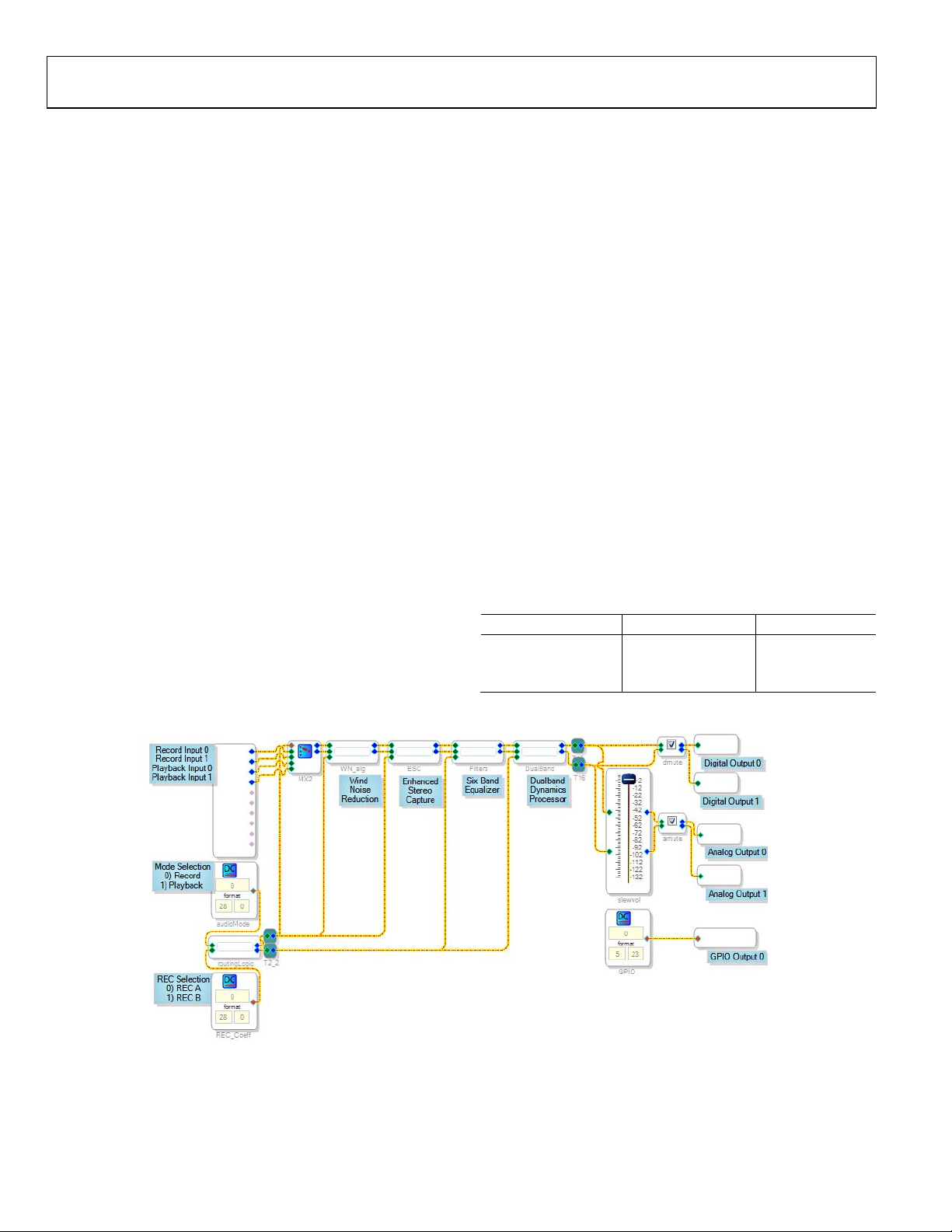
The main page presents an overview of the signal flow, with the
processing blocks of the sound engine presented as hierarchy
boards. Using the main page controls, the audio modes and
output volumes can be modified.
INPUTS
There are four audio inputs to the sound engine: Record Input 0,
Record Input 1, Playback Input 0, and Playback Input 1. The
source of the signals on the record inputs is the ADCs or digital
microphones. Record Input 0 comes from the left ADC or Digital
Microphone Input 1 (the LMIC/LMICN/MICD1 pin), and
Record Input 1 comes from the right ADC or Digital Microphone
Input 2 (the RMIC/RMICN/MICD2 pin). The inputs to the
playback path are from the digital serial data interface. Digital
Serial Input 0 (the left channel of the DAC_SDATA/GPIO0 pin)
is connected to Playback Input 0, and Digital Serial Input
right channel of the DAC_SDATA/GPIO0 pin) is connected to
Playback Input 1.
These two input pairs are routed to the subsequent processing
blocks based on the mode selections. In REC A and REC B
modes, the record input pair is routed through the processing
algorithms; in playback mode, the playback input pair is routed
through the processing algorithms.
1 (the
OUTPUTS AND MUTE
There are four audio outputs from the sound engine: Record
Output 0, Record Output 1, Playback Output 0, and Playback
Output 1. The record output signals (also labeled as Digital
Output 0 and Digital Output 1) are sent to the digital serial
data interface, and the playback output signals (also labeled as
Analog Output 0 and Analog Output 1) go to the DACs of the
ADAU1381. Playback Output 0 is sent to the left DAC, and
Playback Output 1 is sent to the right DAC.
The digital and analog outputs have separate mute settings. In
SigmaStudio, each of these is enabled by checking the appropriate
box for the mute control.
There is a single flag in the sound engine that outputs a high or
a low logic signal on the GPIO pin of the ADAU1381. This
output is set by writing either a 0 or a 1 to the GPIO parameter.
MODE SELECTION
The sound engine can be put into three modes: REC A (Record A),
REC B (Record B), or Playback. Using the settings on the two
mode selection blocks, the routing logic properly configures the
signal flow for the selected mode. The parameter settings for
each mode are shown in Tabl e 1.
Table 1. Record/Playback Modes
Mode Mode Selection REC Selection
REC A (Record A) 0 0
REC B (Record B) 0 1
Playback 1 Don’t care
MAIN PAGE
Figure 2. Main Page
08356-002
Rev. 0 | Page 4 of 40
Page 5
Evaluation Board User Guide UG-030
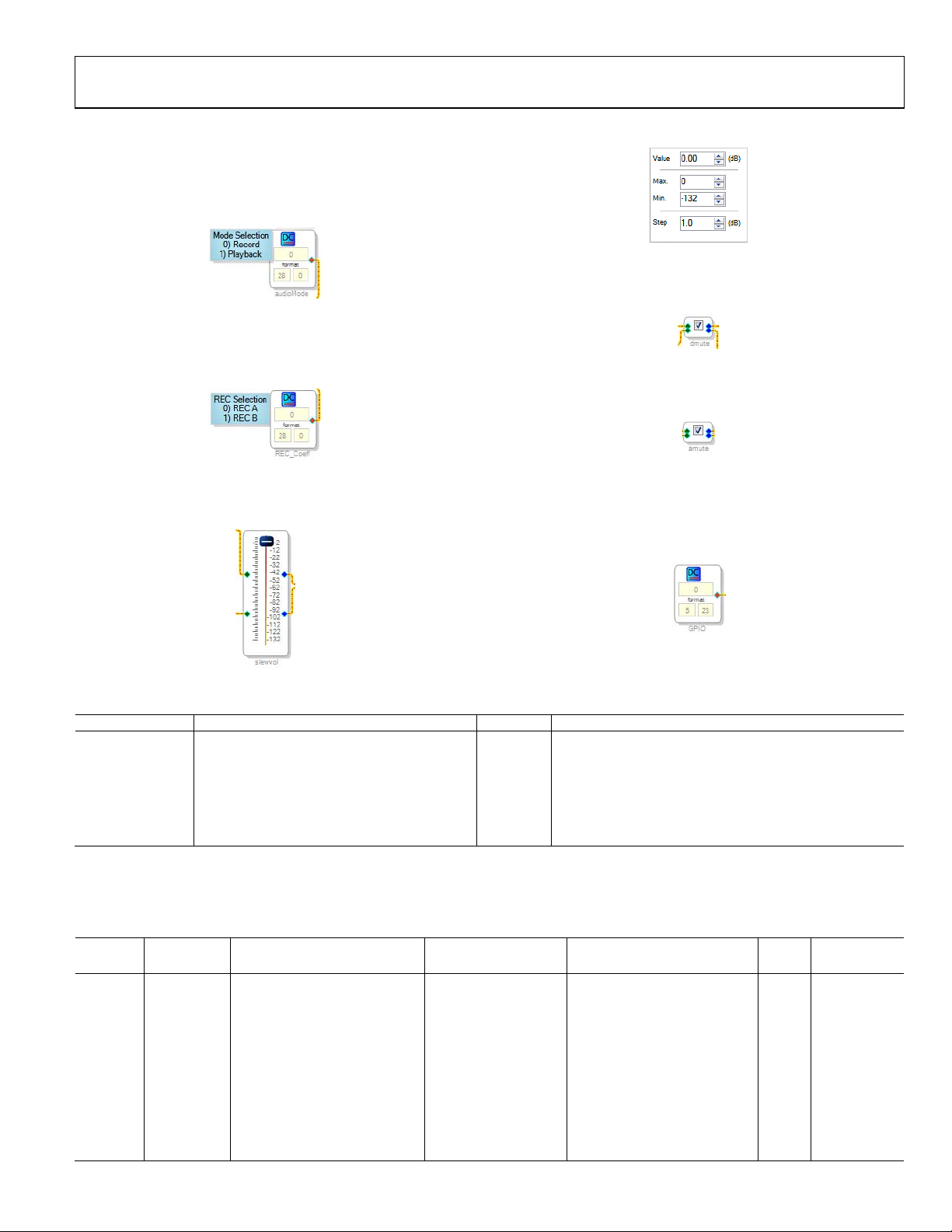
Controls
Set the audio mode by typing 0 or 1 into the audioMode cell in
the default 28.0 format (see Figure 3). More information on 28.0
and other numeric formats can be found in the Numeric Formats
section of the SigmaStudio help file.
08356-003
Figure 3. audioMode Control
Record Mode A (REC A) or Record Mode B (REC B) can be
selected by typing 0 or 1 into the REC_Coeff cell in the default
28.0 format (see Figure 4).
Figure 4. REC_Coeff Control
08356-004
The playback (analog) output volume can be adjusted using the
slewvol cell. Click and drag the slider to select a value (see Figure 5).
Click on the slider to type the value in directly (see Figure 6).
08356-006
Figure 6. slewvol Control Direct Value Entry
Click the dmute cell to disable the record (digital) output
(see Figure 7). A check corresponds to a mute setting.
08356-007
Figure 7. dmute Control
Click the amute cell to disable the playback (analog) output
(see Figure 8). A check corresponds to a mute setting.
Figure 8. amute Control
08356-008
To manually toggle the GPIO output, type a value into the
GPIO cell (see Figure 9). This value is in 5.23 format. More
information on 5.23 and other numeric formats can be found in
the Numeric Formats section of the SigmaStudio help file.
08356-009
08356-005
Figure 5. slewvol Control
Figure 9. GPIO Control
Table 2. Main Page Control Settings
Setting Name Description Default Control Type
audioMode Record/playback selection 0 Function selection
REC_Coeff Selects REC A or REC B path 0 Function selection
slewvol Analog volume control with slew 0 dB Processing parameter
dmute Digital output mute using slew Enabled Processing parameter
amute Analog output mute using slew Enabled Processing parameter
GPIO Sets the GPIO pin high/low (active high) 0 Processing parameter
Parameters
The main page parameters are stored in RAM, as outlined in Table 3 . These addresses can be directly accessed and modified via the
control port of the ADAU1381.
Table 3. Main Page Parameters
Sample Rate
Address Cell Name Parameter Name Default Value Function Bytes
Dependent?
0x0009 audioMode DCInpAlg1 0x00, 0x00, 0x00, 0x00 Set record/playback mode 4 No
0x000A REC_Coeff DCInpAlg3 0x00, 0x00, 0x00, 0x00 Set record mode A or B 4 No
0x000B GPIO DCInpAlg4 0x00, 0x00, 0x00, 0x00 Set GPIO output flag 4 No
0x01B8 slewvol GainS200AlgGrow1gain_target 0x00, 0x80, 0x00, 0x00 Analog output volume control 4 No
0x07FA,
0X07FB
slewvol GainS200AlgGrow1alpha
0x00, 0x7F, 0xF2, 0x59,
0x00, 0x00, 0x0D, 0xA7
Slew rate for analog volume
control
8 Yes
0x01B6 dmute MuteSWLinSlewAlg1mute 0x00, 0x00, 0x00, 0x00 Mute digital (record) output 4 No
0x01B7 dmute MuteSWLinSlewAlg1step 0x00, 0x00, 0x40, 0x00 Slew rate for digital mute 4 Yes
0x01BA amute MuteSWLinSlewAlg2mute 0x00, 0x00, 0x00, 0x00 Mute analog (playback) output 4 No
0x01BB amute MuteSWLinSlewAlg2step 0x00, 0x00, 0x40, 0x00 Slew rate for analog mute 4 Yes
Rev. 0 | Page 5 of 40
Page 6
UG-030 Evaluation Board User Guide
WIND NOISE REDUCTION PAGE
08356-010
Figure 10. Wind Noise Reduction Page
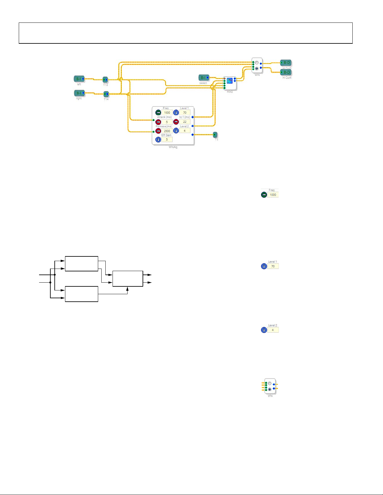
Description
The wind noise reduction page houses the wind noise reduction
algorithm, which uses two microphones to detect and filter wind
noise from the audio signal. Wind noise can easily overwhelm
an audio recording; this reduction algorithm can be used to
lower the effect and increase the clarity of the signal to be recorded.
The algorithm works by detecting the presence of wind noise
and smoothly enabling or disabling a high-pass filter that removes
the noise from the signal. Much of the wind noise that the
microphones pick up is at low frequencies; therefore, the cutoff
frequency of the high-pass filter should be adjusted to adequately
remove the unwanted noise.
such as from a fan blowing across, not directly onto, the
microphones. The value can be entered by clicking the up/
down arrows or by entering text directly in the box.
Figure 12. Freq Control
Level 1 should be tuned while turning the wind source on and
off and simultaneously tuning the parameter setting between 0
and 100. The Level 1 setting is recommended to be between 60
and 90, but this varies depending on the application. The value
can be entered by clicking the up/down arrows or by entering
text directly in the box.
08356-012
FILTERS
L
R
WIND NOIS E
DETECTION
Figure 11. Wind Noise Reduction Block Diagram
WIND NOIS E
REDUCTION
OUTPUTINPUTS
Routing and Bypass
The wind noise reduction processing path is automatically enabled
on the multiplexer (MX3) when the sound engine is put into either
Record Mode A or Record Mode B. When in playback mode, this
mulitplexer bypasses the wind noise reduction algorithm. The
switch on this page (WN) can be used to manually bypass the wind
noise reduction, even in the record modes, if desired.
Controls
Three controls are recommended for in-system tuning:
frequency (Freq), Level 1, and Level 2.
The frequency control sets the detector filters. This parameter
should be tuned so that wind noise is removed, but the desired
audio signal is preserved. The frequency parameter should be
tuned while the system is presented with a constant wind noise,
08356-013
Figure 13. Level 1 Control
Level 2 should be tuned in the same way as Level 1; its settings
range from 0 to 15, with 0 being for strong wind noise and 15 being
08356-011
for a signal with a weak wind noise component. The value can be
entered by clicking the up/down arrows or by entering text directly
in the box.
08356-014
Figure 14. Level 2 Control
The WN switch manually enables or bypasses the algorithm
independently of multiplexer MX3, which allows the algorithm
to be disabled even when a record mode is active. The switch
can be changed by clicking on the appropriate radio button.
08356-015
Figure 15. WN Control
Rev. 0 | Page 6 of 40
Page 7
Evaluation Board User Guide UG-030
Table 4. Wind Noise Reduction Page Control Settings
Setting Name Description Default Control Type
Freq High-pass filter setting 1000 Tune
Attack (ms) Wind noise reduction effect attack time 5 Use default
Release (ms) Wind noise reduction effect release time 2500 Use default
Eff Gain Effect gain 5 Use default
tc 1 (ms) Time constant 22 Use default
Level 1 Level of wind noise reduction 70 Tune
Level 2 Wind noise strength (0 = strong, 15 = weak) 4 Tune
WN Switch Bypass Switch to disable algorithm Enable algorithm Function selection
MX3 Mux Bypass Switch to bypass algorithm (via multiplexer) Enable algorithm Function selection
Parameters
The wind noise reduction page parameters are stored in RAM, as outlined in Tabl e 5. These addresses can be directly accessed and
modified via the control port of the ADAU1381.
Table 5. Wind Noise Reduction Page Parameters
Cell
Address
0x0011 WNAlg WindNoiseAlg2F11 0x00, 0xE8, 0x5D, 0x19 Frequency and effect gain parameters 4 Yes
0x0012 WNAlg WindNoiseAlg2F12 0xFF, 0x95, 0xA1, 0x9C Frequency and effect gain parameters 4 Yes
0x0013 WNAlg WindNoiseAlg2F20 0x00, 0x00, 0x80, 0x53 Frequency and effect gain parameters 4 Yes
0x0014 WNAlg WindNoiseAlg2F21 0x00, 0x01, 0x00, 0xA6 Frequency and effect gain parameters 4 Yes
0x0015 WNAlg WindNoiseAlg2F30 0x00, 0xE8, 0xD0, 0x3A Frequency and effect gain parameters 4 Yes
0x0016 WNAlg WindNoiseAlg2F31 0xFE, 0x2E, 0x5F, 0x8D Frequency and effect gain parameters 4 Yes
0x0017 WNAlg WindNoiseAlg2F42 0x00, 0x80, 0x00, 0x00 Frequency and effect gain parameters 4 Yes
0x0018 WNAlg WindNoiseAlg2tc1 0x00, 0x00, 0x20, 0x00 Time constant 1 (ms) 4 Yes
0x0019 WNAlg WindNoiseAlg2tc11 0x00, 0x7F, 0xE0, 0x00 Time constant 1 (ms) 4 Yes
0x001A WNAlg WindNoiseAlg2tc2 0x00, 0x00, 0x20, 0x00 Time constant 2 (ms) 4 Yes
0x001B WNAlg WindNoiseAlg2tc22 0x00, 0x7F, 0xE0, 0x00 Time constant 2 (ms) 4 Yes
0x001C WNAlg WindNoiseAlg2Level1 0x00, 0x59, 0x99, 0x9A Level 1 4 No
0x001D WNAlg WindNoiseAlg2Level2 0x00, 0x08, 0x00, 0x00 Level 2 4 No
0x001E WNAlg WindNoiseAlg2attack 0x00, 0x00, 0x80, 0x00 Attack (ms) 4 Yes
0x001F WNAlg WindNoiseAlg2release 0x00, 0x00, 0x00, 0x40 Release (ms) 4 Yes
0x0020 WN stereomux1940ns40 0x00, 0x00, 0x00, 0x00
0x0021 WN stereomux1940ns41 0x00, 0x80, 0x00, 0x00
Name Parameter Name Default Value Function Bytes
On/off (burst write Address 0x0020
and Address 0x0021 together)
On/off (burst write Addresses 0x0020
and Address 0x0021 together)
4 No
4 No
Sample Rate
Dependent?
Rev. 0 | Page 7 of 40
Page 8
UG-030 Evaluation Board User Guide
ENHANCED STEREO CAPTURE PAGE
08356-016
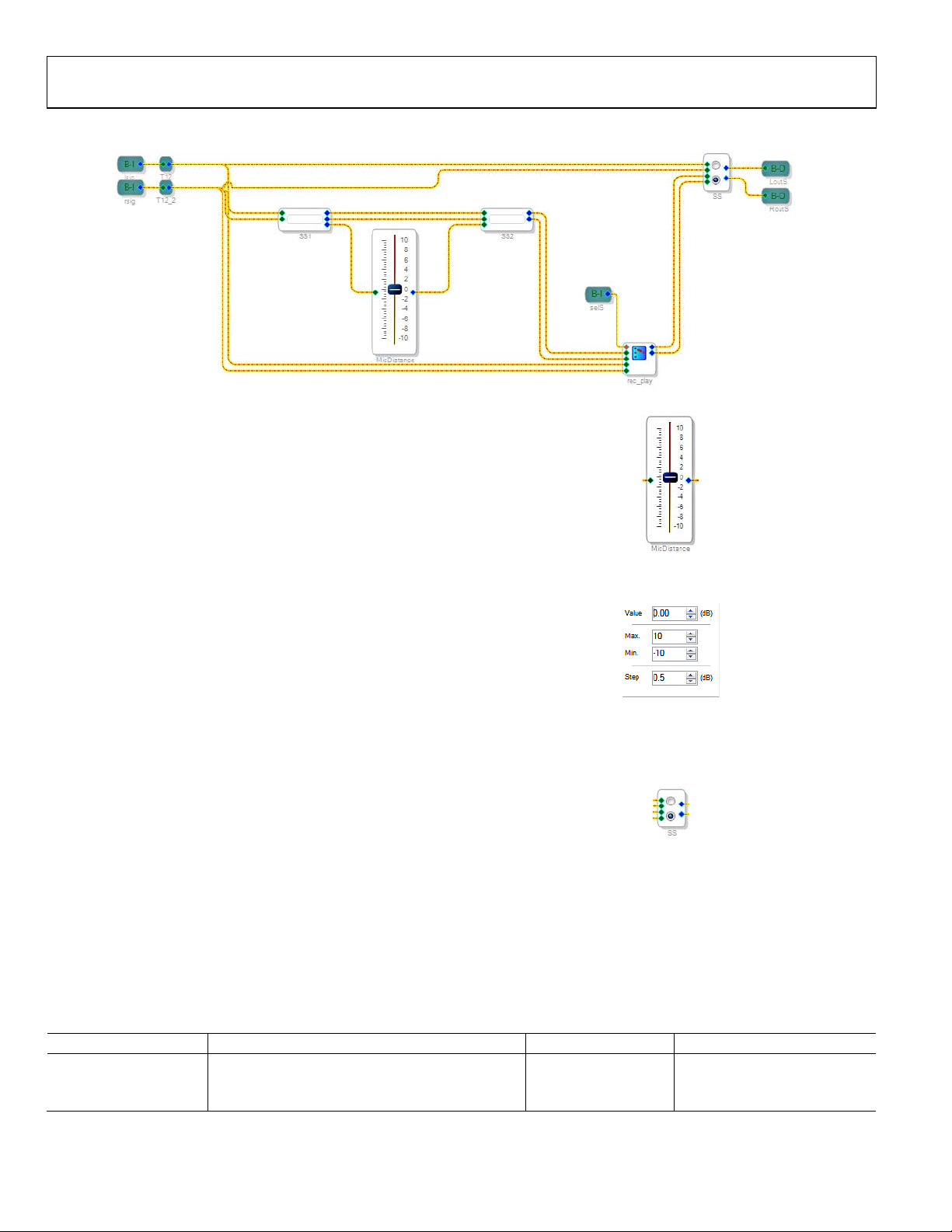
Figure 16. Enhanced Stereo Capture Page
Description
The enhanced stereo capture (ESC) algorithm takes a stereo record
signal and creates a wider stereo image. ESC is used as a recording
algorithm to capture an enhanced stereo image from two closely
spaced microphones.
The ESC algorithm takes two input signals from two closely
spaced microphones. The algorithm separates these two signals
and widens the stereo image. The result is a perceived widened
stereo image as if the audio was captured by microphones with
greater left/right separation. ESC is based on proprietary filtering
and a stereo balance gain that adjusts how much stereo effect is
achieved in the algorithm.
Routing and Bypass
The enhanced stereo capture path is automatically enabled on
the mux (rec_play) when the sound engine is put into either
REC A or REC B. When in playback mode, the mux bypasses
the wind noise reduction algorithm. The switch on this page
(SS) can be used to bypass the enhanced stereo capture, even in
the record modes, if desired.
Controls
The MicDistance control can be set from −10 to +10, with a
default value of 0 (see Figure 17). This control determines the
sensitivity of the ESC algorithm and directly affects the level of
stereo enhancement perceived in the recorded signal. Increasing
the enhancement too much may result in an unnatural quality
in the recorded audio. This control may vary greatly depending
on factors such as microphone selection, spacing, and housing.
Therefore, it must be tuned to fit the needs of a specific design.
Figure 17. MicDistance Control
08356-017
Right-click the slider to enter the value directly (see Figure 18).
8356-018
Figure 18. MicDistance Control Direct Value Entry
The SS switch allows the algorithm to be bypassed independently
of the rec_play multiplexer and the active audio mode. The
switch can be changed by clicking on the appropriate radio button.
08356-019
Figure 19. SS Control
Table 6. ESC Page Control Settings
Setting Name Description Default Control Type
MicDistance Control enhancement level 0 Tune
SS Switch Bypass Switch to disable algorithm Algorithm enabled Function selection
rec_play Mux Bypass Switch to bypass algorithm (via multiplexer) Algorithm enabled Function selection
Rev. 0 | Page 8 of 40
Page 9
Evaluation Board User Guide UG-030
Parameters
The enhanced stereo capture page parameters are stored in RAM, as outlined in Tabl e 7. These addresses can be directly accessed and
modified via the control port of the ADAU1381.
Table 7. ESC Page Parameters
Sample Rate
Address Cell Name Parameter Name Default Value Function Bytes
0x0029 MicDistance Gain1940AlgNS1 0x00, 0x80, 0x00, 0x00
0x002B SS stereomux1940ns30 0x00, 0x00, 0x00, 0x00
0x002C SS stereomux1940ns31 0x00, 0x80, 0x00, 0x00
0x0023 Locked Cell param1 0x00, 0xCA, 0x9A, 0x58
0x0024 Locked Cell param2 0x0F, 0x35, 0x65, 0xA8
0x0025 Locked Cell param3 0x00, 0x7F, 0xAA, 0xE7
0x0026 Locked Cell param4 0x00, 0x08, 0x38, 0x65
0x0027 Locked Cell param5 0x00, 0x00, 0x00, 0x00
0x0028 Locked Cell param6 0x00, 0x7B, 0x1A, 0x7E
Gain setting related to the distance
between microphones that enhances
the perceived effect
On/off (burst write Address0x002B
and Address 0x002C together)
On/off (burst write Address 0x002B
and Address 0x002C together)
Locked parameter (generated by
SigmaStudio)
Locked parameter (generated by
SigmaStudio)
Locked parameter (generated by
SigmaStudio)
Locked parameter (generated by
SigmaStudio)
Locked parameter (generated by
SigmaStudio)
Locked parameter (generated by
SigmaStudio)
4 No
4 No
4 No
4 Yes
4 Yes
4 Yes
4 Yes
4 Yes
4 Yes
EQUALIZATION FILTERS PAGE
Dependent?
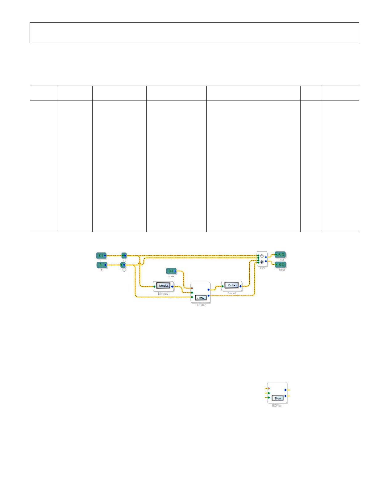
Figure 20. Equalization Filters Page
Description
Equalization (EQ) filters are used to tune the frequency response of
the recorded or played back audio signal. The ADAU1381 sound
engine includes three, six-band EQ paths, one for playback and
the other two for different recording scenarios, such as music
recording and voice.
Each EQ band is implemented as a double-precision biquad
filter. These filters can be used in a wide variety of configurations,
such as low-pass, high-pass, band-pass, parametric, shelving,
peaking, tone control, and others.
Routing and Bypass
There are three, six-band EQ paths in the sound engine: one
each for Record A (REC A), Record B (REC B), and Playback
modes. Path 0 (top row) is the EQ filters for Record A (REC A),
Path 1 (middle row) is the EQ filters for Record B (REC B), and
Path 2 (bottom row) is the filters for the playback processing.
Rev. 0 | Page 9 of 40
08356-020
The appropriate path is automatically selected when the mode is
selected on the main page
The switch
on this page (filtS) can be used to completely bypass
.
the EQFilter, if desired.
Controls
Click Show on the EQFilter cell to configure the filter bands
(see Figure 21).
Figure 21. EQFilter Control with Show Button
08356-021
Page 10
UG-030 Evaluation Board User Guide
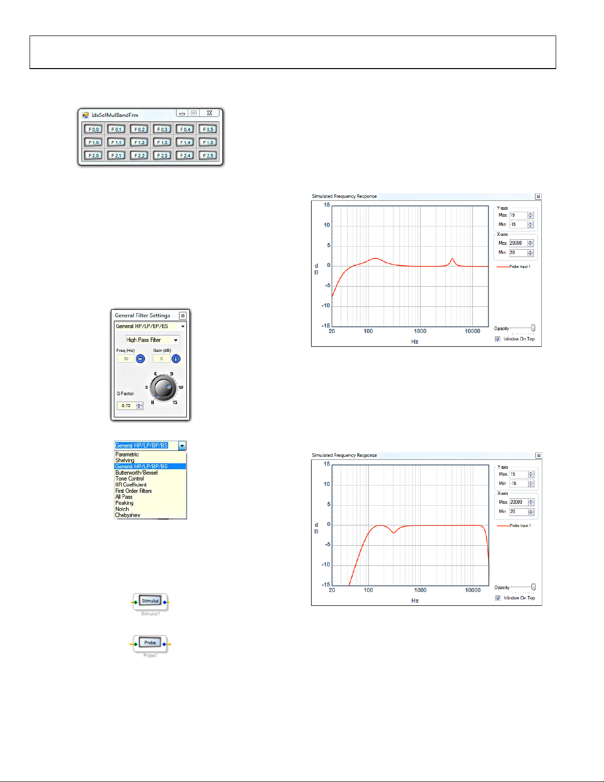
When Show is clicked, it displays a filter matrix with three rows
and six columns (see Figure 22).
022
Figure 22. EQFilter Matrix
08356-
The first row represents the six bands of the Record A (REC A)
mode, the second
row represents the six bands of the Record B
(REC B) mode, and the third row represents the six bands of the
Playback mode.
Each button in the matrix contains a single second-order biqua
d
filter. To individually tune a filter, click its corresponding button.
Clicking the menu at the top of the General Filter Settings
window provides access to a large variety of filters, each with its
own property pages and controls (see Figure 23 and Figure 24).
The Simulated Frequency Response window displays a
calculated frequency response for each of the filter bands. It
shows only one EQ curve at a time, the one corresponding to
the filter mode that was last edited.
By default, the EQ curve for Record A (REC A) mode is configured
for voice recording (see Figure 27). The high-pass filter removes
low frequencies that are not necessary for voice recording. The
wide boost in the 150 Hz range amplifies the voice fundamental
frequencies, and the narrow boost near 4 kHz increases vocal clarity.
08356-023
Figure 23. Individual Filter Band Settings
Figure 24. F
ilter Type Selection
024
08356-
More information on the various filters is available in the Help
menu within SigmaStudio.
Click Stimulus and Probe to open the Simulated Frequency
Response window (see Figure 25 and gure 26).
Figure 25. Stimulus Button
Fi
8356-025
08356-027
Figure 27. Default Record A (REC A) Mode EQ Curve
By default, the EQ curve for Record B (REC B) mode is configured
for music and live concert recording (see Figure 28). The highpass filter removes low frequency boom and rumble from a
concert recording environment. The cut in the midbass range
around 300 Hz helps to increase the perceived level of the bass.
The low-pass filter on the high frequency range helps to reduce
ringing caused by reflections in a loud concert environment.
8356-028
Figure 28. Default Record B (REC B) Mode EQ Curve
8356-026
Figure 26. Probe Button
Rev. 0 | Page 10 of 40
Page 11
Evaluation Board User Guide UG-030
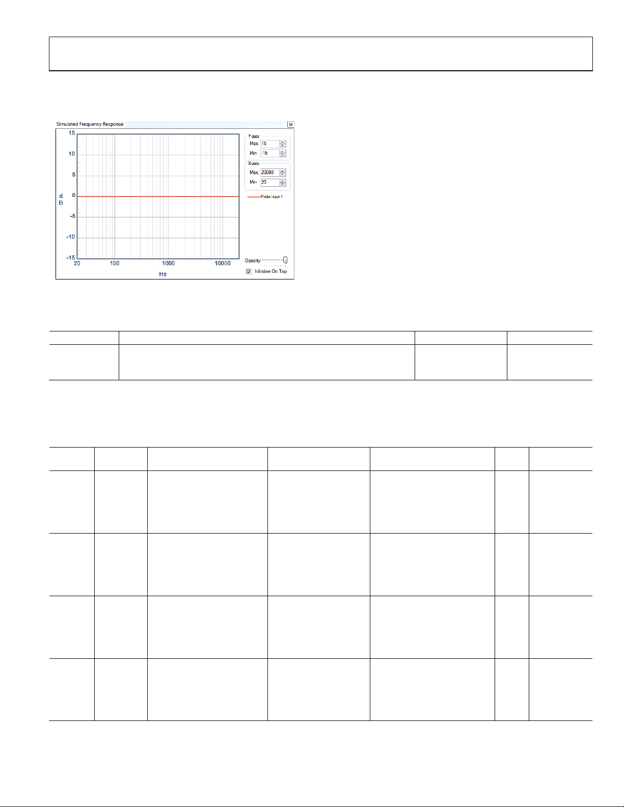
By default, the EQ curve for Playback mode is flat, which should
be changed accordingly to compensate for nonlinearities due to
the speaker design and housing (see Figure 29).
8356-029
Figure 29. Default Playback Mode EQ Curve
Table 8. EQ Page Control Settings
Setting Name Description Default Control Type
EQFilter Three parallel six-band equalizers with independently controllable bands
filtS Switch to disable algorithm Algorithm enabled Function selection
The default EQ curves are intended only as examples and
should be specifically tuned for the target application system.
Example curves for
record and playback
Tune
Parameters
The equalization filters page parameters are stored in RAM, as outlined in Tab le 9. These addresses can be directly accessed and modified
via the control port of the ADAU1381.
Table 9. EQ Page Parameters
Sample Rate
Address Cell Name Parameter Name Default Value Function Bytes
0x002D EQFilter IndexSelMultBandAlg100b2 0x00, 0x7F, 0xAA, 0x50, Biquad F0, 0 20 Yes
0x002E 0xFF, 0x00, 0xAB, 0x60,
0x002F 0x00, 0x7F, 0xAA, 0x50,
0x0030 0xFF, 0x80, 0xAB, 0x20,
0x0031 0x00, 0xFF, 0x54, 0x5F
0x0032 EQFilter IndexSelMultBandAlg101b2 0x00, 0x7D, 0xBD, 0xAF, Biquad F0, 1 20 Yes
0x0033 0xFF, 0x02, 0x0A, 0x2E,
0x0034 0x00, 0x80, 0x42, 0x4A,
0x0035 0xFF, 0x82, 0x00, 0x07,
0x0036 0x00, 0xFD, 0xF5, 0xD2
0x0037 EQFilter IndexSelMultBandAlg102b2 0x00, 0x00, 0x00, 0x00, Biquad F0, 2 20 Yes
0x0038 0x00, 0x00, 0x00, 0x00,
0x0039 0x00, 0x80, 0x00, 0x00,
0x003A 0x00, 0x00, 0x00, 0x00,
0x003B 0x00, 0x00, 0x00, 0x00
0x003C EQFilter IndexSelMultBandAlg103b2 0x00, 0x00, 0x00, 0x00, Biquad F0, 3 20 Yes
0x003D 0x00, 0x00, 0x00, 0x00,
0x003E 0x00, 0x80, 0x00, 0x00,
0x003F 0x00, 0x00, 0x00, 0x00,
0x0040 0x00, 0x00, 0x00, 0x00
Dependent?
Rev. 0 | Page 11 of 40
Page 12

UG-030 Evaluation Board User Guide
Sample Rate
Address Cell Name Parameter Name Default Value Function Bytes
0x0041 EQFilter IndexSelMultBandAlg104b2 0x00, 0x71, 0xCB, 0x91, Biquad F0, 4 20 Yes
0x0042 0xFF, 0x2E, 0xCC, 0xE6,
0x0043 0x00, 0x81, 0xA0, 0xD2,
0x0044 0xFF, 0x8C, 0x93, 0x9D,
0x0045 0x00, 0xD1, 0x33, 0x1A
0x0046 EQFilter IndexSelMultBandAlg105b2 0x00, 0x00, 0x00, 0x00, Biquad F0, 5 20 Yes
0x0047 0x00, 0x00, 0x00, 0x00,
0x0048 0x00, 0x80, 0x00, 0x00,
0x0049 0x00, 0x00, 0x00, 0x00,
0x004A 0x00, 0x00, 0x00, 0x00
0x004B EQFilter IndexSelMultBandAlg110b2 0x00, 0x7E, 0xFB, 0x24, Biquad F1, 0 20 Yes
0x004C 0xFF, 0x02, 0x09, 0xB7,
0x004D 0x00, 0x7E, 0xFB, 0x24,
0x004E 0xFF, 0x82, 0x06, 0xEE,
0x004F 0x00, 0xFD, 0xF3, 0x80
0x0050 EQFilter IndexSelMultBandAlg111b2 0x00, 0x7D, 0xEB, 0x86, Biquad F1, 1 20 Yes
0x0051 0xFF, 0x02, 0x83, 0x95,
0x0052 0x00, 0x7F, 0xC2, 0xF7,
0x0053 0xFF, 0x82, 0x51, 0x83,
0x0054 0x00, 0xFD, 0x7C, 0x6B
0x0055 EQFilter IndexSelMultBandAlg112b2 0x00, 0x00, 0x00, 0x00, Biquad F1, 2 20 Yes
0x0056 0x00, 0x00, 0x00, 0x00,
0x0057 0x00, 0x80, 0x00, 0x00,
0x0058 0x00, 0x00, 0x00, 0x00,
0x0059 0x00, 0x00, 0x00, 0x00
0x005A EQFilter IndexSelMultBandAlg113b2 0x00, 0x00, 0x00, 0x00, Biquad F1, 3 20 Yes
0x005B 0x00, 0x00, 0x00, 0x00,
0x005C 0x00, 0x80, 0x00, 0x00,
0x005D 0x00, 0x00, 0x00, 0x00,
0x005E 0x00, 0x00, 0x00, 0x00
0x005F EQFilter IndexSelMultBandAlg114b2 0x00, 0x00, 0x00, 0x00, Biquad F1, 4 20 Yes
0x0060 0x00, 0x00, 0x00, 0x00,
0x0061 0x00, 0x80, 0x00, 0x00,
0x0062 0x00, 0x00, 0x00, 0x00,
0x0063 0x00, 0x00, 0x00, 0x00
0x0064 EQFilter IndexSelMultBandAlg115b2 0x00, 0x4A, 0x91, 0x00, Biquad F1, 5 20 Yes
0x0065 0x00, 0x95, 0x22, 0x00,
0x0066 0x00, 0x4A, 0x91, 0x00,
0x0067 0xFF, 0xD1, 0x47, 0xB1,
0x0068 0xFF, 0x84, 0x74, 0x4F
0x0069 EQFilter IndexSelMultBandAlg120b2 0x00, 0x00, 0x00, 0x00, Biquad F2, 0 20 Yes
0x006A 0x00, 0x00, 0x00, 0x00,
0x006B 0x00, 0x80, 0x00, 0x00,
0x006C 0x00, 0x00, 0x00, 0x00,
0x006D 0x00, 0x00, 0x00, 0x00
0x006E EQFilter IndexSelMultBandAlg121b2 0x00, 0x00, 0x00, 0x00, Biquad F2, 1 20 Yes
0x006F 0x00, 0x00, 0x00, 0x00,
0x0070 0x00, 0x80, 0x00, 0x00,
0x0071 0x00, 0x00, 0x00, 0x00,
0x0072 0x00, 0x00, 0x00, 0x00
Dependent?
Rev. 0 | Page 12 of 40
Page 13

Evaluation Board User Guide UG-030
Sample Rate
Address Cell Name Parameter Name Default Value Function Bytes
0x0073 EQFilter IndexSelMultBandAlg122b2 0x00, 0x00, 0x00, 0x00, Biquad F2, 2 20 Yes
0x0074 0x00, 0x00, 0x00, 0x00,
0x0075 0x00, 0x80, 0x00, 0x00,
0x0076 0x00, 0x00, 0x00, 0x00,
0x0077 0x00, 0x00, 0x00, 0x00
0x0078 EQFilter IndexSelMultBandAlg123b2 0x00, 0x00, 0x00, 0x00, Biquad F2, 3 20 Yes
0x0079 0x00, 0x00, 0x00, 0x00,
0x007A 0x00, 0x80, 0x00, 0x00,
0x007B 0x00, 0x00, 0x00, 0x00,
0x007C 0x00, 0x00, 0x00, 0x00
0x007D EQFilter IndexSelMultBandAlg124b2 0x00, 0x00, 0x00, 0x00, Biquad F2, 4 20 Yes
0x007E 0x00, 0x00, 0x00, 0x00,
0x007F 0x00, 0x80, 0x00, 0x00,
0x0080 0x00, 0x00, 0x00, 0x00,
0x0081 0x00, 0x00, 0x00, 0x00
0x0082 EQFilter IndexSelMultBandAlg125b2 0x00, 0x00, 0x00, 0x00, Biquad F2, 5 20 Yes
0x0083 0x00, 0x00, 0x00, 0x00,
0x0084 0x00, 0x80, 0x00, 0x00,
0x0085 0x00, 0x00, 0x00, 0x00,
0x0086 0x00, 0x00, 0x00, 0x00
0x008E filtS stereomux1940ns10 0x00, 0x00, 0x00, 0x00
0x008F filtS stereomux1940ns11 0x00, 0x80, 0x00, 0x00
On/off (burst write
Address 0x008E and
Address 0x008F together)
On/off (burst write
Address 0x008E and
Address 0x008F together)
4 No
4 No
Dependent?
Rev. 0 | Page 13 of 40
Page 14
UG-030 Evaluation Board User Guide
DUAL-BAND COMPRESSION PAGE
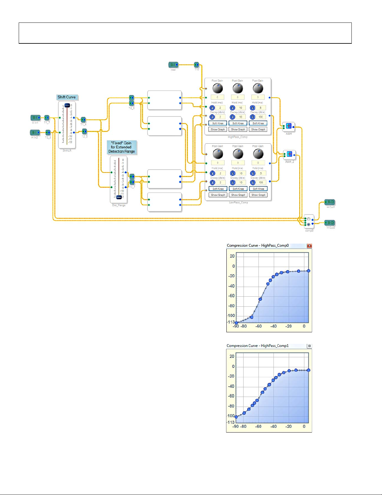
Figure 30. Dual-Band Compression Page
Description
The dual-band compression page contains dynamic processors
designed to alter the dynamic range of the audio signal during
record or playback. To provide high audio quality, the input
signal is sent into a crossover network that divides it into high
and low bands. Each band is detected and processed individually.
The end result is that a sudden peak in one band (for example, a
kick drum in the low band) will not cause a dip in the overall
signal level.
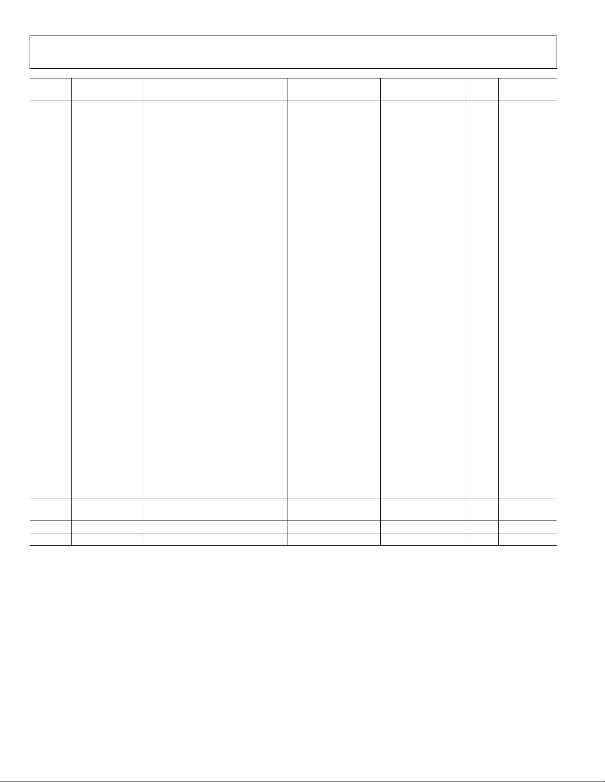
Available Curves
By default, the record modes are configured with an automatic
level control (ALC) curve, and the playback mode is configured
with a standard compressor curve with a threshold of −6 dB and a
ratio of 2:1. The Record A (REC A) mode curve is an example
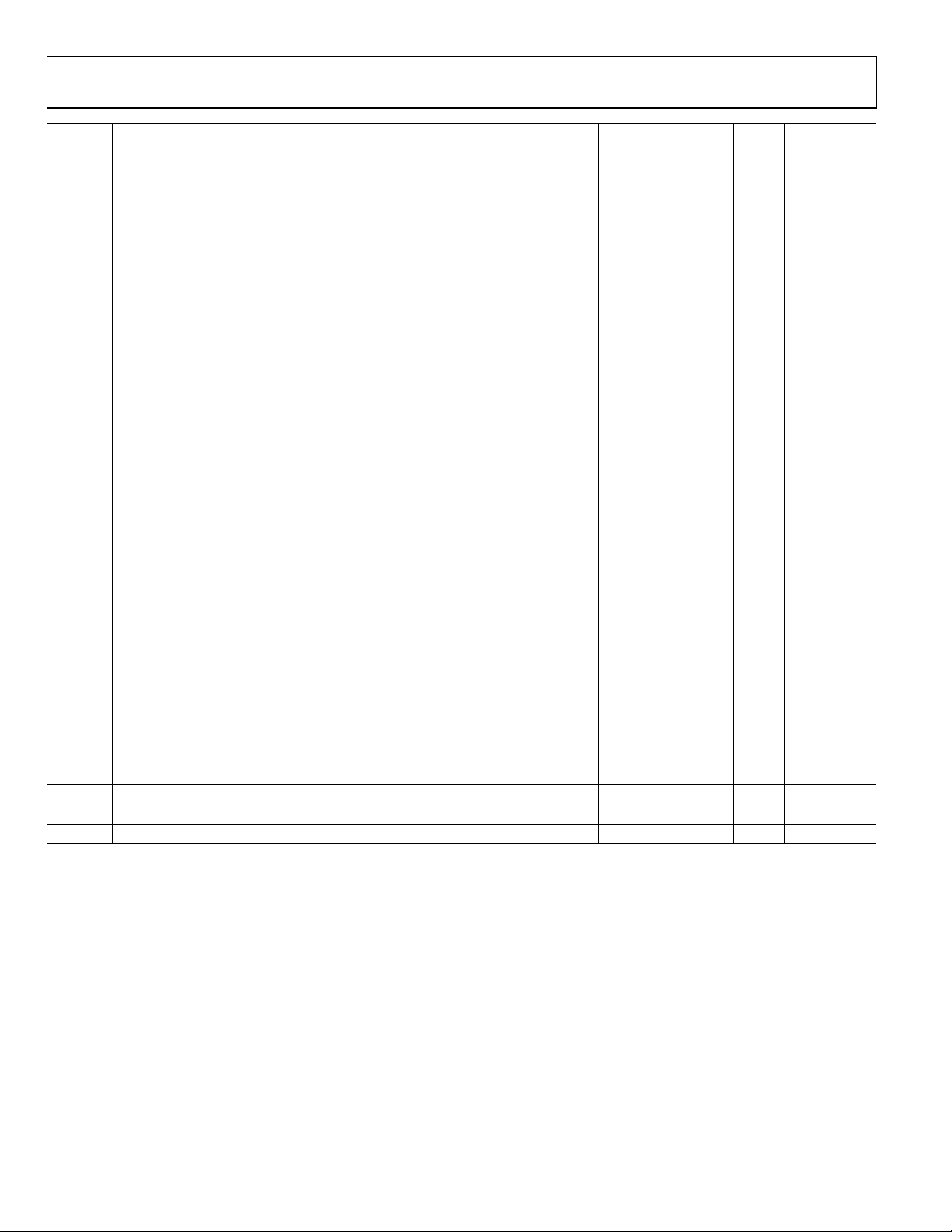
of hard ALC compression (see Figure 31), and the Record B (REC B)
mode curve is an example of smoothed ALC compression
(see Figure 32). The playback mode compressor curve has
moderate compression starting at a threshold of −8 dB
(see Figure 33). These default curves are intended only to be
examples. The desired curve varies greatly depending on the
application and other factors in the system. Therefore, unique
curves should be created during the
tuning process.
Figure 31, Figure 32, and Figure 33 show examples of compressor
curves. The curves represent a transfer function, with the
horizontal axis representing input in dB and the vertical axis
representing the resulting output in dB.
08356-031
Figure 31. Default Record A (REC A) Mode Compressor Curve
Figure 32. Default Record B (REC B) Mode Compressor Curve
08356-032
08356-030
Rev. 0 | Page 14 of 40
Page 15

Evaluation Board User Guide UG-030
Detection Range Shift
The detection range control shifts the range over which the
compressor operates. The algorithm typically handles inputs
ranging from −90 dB to +6 dB. Any inputs outside of this range
have a linear input-to-output relationship, effectively ignoring
the compression curve. In applications where inputs to the
compressor greater than 6 dB are expected, the detection range
can be shifted to accommodate the input signal range. The
default shift of −12 dB changes the detection range’s lower
bound to −78 dB and its upper bound to +18 dB. This curve
8356-033
Figure 33. Default Playback Mode Compressor Curve
Curve Shift
The compressor curves can be shifted to the right using the
ShiftLR control. This changes the input gain of the audio and
detects signals routed to the compressor. The default value of
0 dB represents no shift from the original curve. Decreasing this
value translates the compressor curves directly to the right by a
corresponding amount. Note that there is no graphical difference
shown on the compressor curve graphs, but the compressor curve
points effectively shift directly to the right as the value of the
slider decreases. The maximum shift allowed is 12 dB.
For a classic compression curve (linear compression ratio for
low amplitudes and a ratio greater than 1 after a certain
threshold), the ShiftLR control effectively increases the
threshold value. The ShiftLR control allows a curve to be
shifted at run time without requiring a download of new
compression table parameters via the control port.
Figure 34 shows an example of curve shift being applied to an
example compression curve with a gate below −80 dB, a linear
transfer function between −80 dB and −28 dB, and a compression
ratio of 2:1 for input amplitudes greater than −28 dB. The example
curve is shown furthest to the left. Shifted curves for −3 dB, −6 dB,
−9 dB, and −12 dB are shown to the right of the example curve.
For all shifted curves, the compression threshold remains constant,
but the gate threshold changes. The output gain for the linear
section of the input range decreases as the curve shifts to the right.
20
0
–20
–40
–60
OUTPUT LEVEL (dB)
–80
–100
–113
–90 0–20–40–60–80
Figure 34. Curve Shift L/R Example
INPUT LEVEL (dB)
08356-034
shift must correspond to the compressors Adjust Gain Curve
setting, shown in Figure 39.
The compression curve displayed in the compression curve graph
represents a detection range shift of 0 dB. Decreasing the detection
range effectively shifts the curve upward and to the right.
The detection range shift should be determined during system
tuning and should not be altered when the system is in operation.
Figure 35 shows an example of detection range shift being
applied to an example compression curve with a gate below
−80 dB, a linear transfer function between −80 dB and −28 dB,
and a compression ratio of 2:1 for input amplitudes greater than
−28 dB. The example curve is shown furthest to the bottom and
the left. Shifted curves for −3 dB, −6 dB, −9 dB, and −12 dB are
shown above and to the right of the example curve. For all shifted
curves, both the compression and gate thresholds increase, but
the linear section of the input range remains linear.
20
0
–20
–40
–60
OUTPUT LEVEL (dB)
–80
–100
–113
–90 0–20–40–60–80
Figure 35. Detection Range Shift Example
INPUT LEVEL (dB)
08356-035
Routing and Bypass
The dual-band compression algorithm is enabled by default in
all audio modes. The compS switch allows the dual-band
compressor to be bypassed manually.
Rev. 0 | Page 15 of 40
Page 16

UG-030 Evaluation Board User Guide
Controls
The ShiftLR control shifts the compression curve horizontally.
The slider can be dragged to change the value (see Figure 36).
The default value of 0 dB indicates that the transfer function
displayed in the compression curve editor matches the processing
in the sound engine. Decreasing the value of the control shifts
the curve to the right.
08356-036
Figure 36. ShiftLR Control
Right-click the slider to type the value in directly (see Figure 37).
Figure 37. ShiftLR Control Direct Value Entry
The Det_Range control shifts the compression curve diagonally
(see Figure 38). The Det_Range value can be controlled by
dragging the slider or by entering the value manually by rightclicking the slider. The Det_Range control is only intended to
take on the following values: 0 dB, −3 dB, −6 dB, −9 dB, and −12 dB.
08356-039
Figure 39. Changing the Detection Curve of a Compressor
Each frequency band (low and high) is fed into a stereo
compressor matrix (see Figure 40). Each matrix contains three
compressors, one for each audio mode. The left column
08356-037
corresponds to Record A (REC A) mode, the center column
corresponds to Record B (REC B) mode, and the right column
corresponds to Playback mode.
08356-038
Figure 38. Det_Range Control
When the detection range is modified, the compressors must
also be configured to match. By default, the compressors are
configured for a detection range shift of −12 dB. To change the
compressor detection range, click on a compressor cell, select
the Adjust Gain Curve option, and select the value matching
the setting of the Det_Range control (see Figure 39). Complete
this process for both the high-band and low-band compressors.
Rev. 0 | Page 16 of 40
Figure 40. HighPass_Comp Control
08356-040
Each compressor column contains a Post Gain control that adjusts
the amount of gain applied to the signal at the output of the
compressor (see Figure 41).
08356-041
Figure 41. Post Gain Control
The Hold (ms) control sets the duration that the gain reduction
ratio of the compressor is held after it is set by the input signal
(see Figure 42).
08356-042
Figure 42. Hold (ms) Control
Page 17

Evaluation Board User Guide UG-030
3
4
The Decay (dB/s) control sets the speed by which the gain
reduction ratio decays after the hold duration expires
(see Figure 4
3).
Figure 43. Decay (dB/s) Control
08356-04
Click the Soft Knee button to smooth the corners (also known
as knees) of the Compression Curve (see Figure 44).
08356-04
Figure 44. Soft Knee Button
Click the Show Graph button to display the Compression
Curve graphical editor (see Figure 45).
08356-045
Figure 45. Show Graph Button
The Compression Curve editor displays a graphical representation
of the input/output gain transfer function, which is a curve with
33 points (see Figure 46). The horizontal axis represents the input
level, and the vertical axis represents the output level. Each large
point can be dragged to a new position on the graph.
Click on a point within the graph to display the Compression
Curve Point Option menu. This is where large points can be
added, removed, or fine-tuned (see Figure 47).
08356-047
Figure 47. Compression Curve Point Option Menu
Click on a set point value to display a dialog box where the
coordinates of the point can be entered manually (see Figure 48).
08356-048
Figure 48. Compression Curve Point Direct Value Entry
The compS switch allows the dual-band compressors to be
bypassed (see Figure 49). Click on the appropriate radio button
to change the switch.
8356-049
Figure 49. compS Control
08356-046
Figure 46. Compression Curve Editor
Table 10. Dual-Band Compression Page Control Settings
Setting Name Description Default Control Type
ShiftLR Shift curve left/right 0 Tune
Det_Range Fixed gain for extended detection range −12 Tune
CrossHi Crossover for high frequencies N/A Locked
CrossLo Crossover for low frequencies N/A Locked
HiDet Filter Filter for high frequency detector N/A Locked
LoDet Filter Filter for low frequency detector N/A Locked
HIGH-PASS COMPRESSOR
Post Gain (dB) Gain applied to the output of the compressor 0 Tune
Hold (ms)
Duration that the gain reduction ratio of the compressor
2 Tune
is held after it is set by the input signal
Decay (dB/s)
Speed that the gain reduction ratio of the compressor
2 Tune
decreases after the hold time expires
Soft Knee Smooths the compression curve Active Tune
Graph Editor
Graphical entry of compression curve (input/output
gain transfer function)
Default compression
curves
Tune
Rev. 0 | Page 17 of 40
Page 18

UG-030 Evaluation Board User Guide
Setting Name Description Default Control Type
LOW-PASS COMPRESSOR
Post Gain (dB) Gain applied to the output of the compressor 0 Tune
Hold (ms)
Decay (dB/s)
Soft Knee Smooths the compression curve Active Tune
Graph Editor
compS Switch/mux bypass Algorithm enabled Function selection
Duration that the gain reduction ratio of the compressor
is held after it is set by the input signal
Speed that the gain reduction ratio of the compressor
decreases after the hold time expires
Graphical entry of compression curve (input/output
gain transfer function)
Parameters
The dual-band compression page parameters are stored in RAM, as outlined in Ta ble 1 1. These addresses can be directly accessed and
modified via the control port of the ADAU1381.
Table 11. Dual-Band Compression Page Parameters
Address Cell Name Parameter Name Default Value Function Bytes
0x0090 ShiftLR Gain1940AlgNS4 0x00, 0x80, 0x00, 0x00
0x0091 ShiftLR Gain1940AlgNS5 0x00, 0x80, 0x00, 0x00
0x0092 Det_Range Gain1940AlgNS3 0x00, 0x20, 0x26, 0xF3
0x0093 Det_Range Gain1940AlgNS2 0x00, 0x20, 0x26, 0xF3
0x00A2 CrossHi EQwSubDualDP32B1 0x00, 0x7B, 0xEB, 0x74
0x00A3 CrossHi EQwSubDualDP31B1 0x0F, 0x08, 0x29, 0x18
0x00A4 CrossHi EQwSubDualDP30B1 0x00, 0x7B, 0xEB, 0x74
0x00A5 CrossHi EQwSubDualDP32A1 0x0F, 0x88, 0x07, 0xC9
0x00A6 CrossHi EQwSubDualDP31A1 0x00, 0xF7, 0xB5, 0x9A
0x00A7 CrossHi EQwSubDualDP32B2 0x00, 0x7B, 0xEB, 0x74
0x00A8 CrossHi EQwSubDualDP31B2 0x0F, 0x08, 0x29, 0x18
0x00A9 CrossHi EQwSubDualDP30B2 0x00, 0x7B, 0xEB, 0x74
0x00AA CrossHi EQwSubDualDP32A2 0x0F, 0x88, 0x07, 0xC9
0x00AB CrossHi EQwSubDualDP31A2 0x00, 0xF7, 0xB5, 0x9A
2 Tune
2 Tune
Default compression
curves
Shift curve left/right;
Address 0x0090 and
Address 0x0091
must contain
the same value
Shift curve left/right;
Address 0x0090 and
Address 0x0091
must contain
the same value
On/off (burst write
Address 0x0092 and
Address 0x0093
together)
On/off (burst write
Address 0x0092 and
Address 0x0093
together)
Crossover HPF filter
coefficient
Crossover HPF filter
coefficient
Crossover HPF filter
coefficient
Crossover HPF filter
coefficient
Crossover HPF filter
coefficient
Crossover HPF filter
coefficient
Crossover HPF filter
coefficient
Crossover HPF filter
coefficient
Crossover HPF filter
coefficient
Crossover HPF filter
coefficient
Tune
Sample Rate
Dependent?
4 No
4 No
4 No
4 No
4 Yes
4 Yes
4 Yes
4 Yes
4 Yes
4 Yes
4 Yes
4 Yes
4 Yes
4 Yes
Rev. 0 | Page 18 of 40
Page 19

Evaluation Board User Guide UG-030
Sample Rate
Address Cell Name Parameter Name Default Value Function Bytes
0x0094 CrossLo EQwSubDualDP42B1 0x00, 0x00, 0x10, 0xA7
0x0095 CrossLo EQwSubDualDP41B1 0x00, 0x00, 0x21, 0x4E
0x0096 CrossLo EQwSubDualDP40B1 0x00, 0x00, 0x10, 0xA7
0x0097 CrossLo EQwSubDualDP42A1 0x0F, 0x88, 0x07, 0xC9
0x0098 CrossLo EQwSubDualDP41A1 0x00, 0xF7, 0xB5, 0x9A
0x0099 CrossLo EQwSubDualDP42B2 0x00, 0x00, 0x10, 0xA7
0x009A CrossLo EQwSubDualDP41B2 0x00, 0x00, 0x21, 0x4E
0x009B CrossLo EQwSubDualDP40B2 0x00, 0x00, 0x10, 0xA7
0x009C CrossLo EQwSubDualDP42A2 0x0F, 0x88, 0x07, 0xC9
0x009D CrossLo EQwSubDualDP41A2 0x00, 0xF7, 0xB5, 0x9A
0x00BE HiDet_Filter EQwSubDualDP52B1 0x00, 0x7D, 0x44, 0xE0
0x00BF HiDet_Filter EQwSubDualDP51B1 0x0F, 0x05, 0x76, 0x40
0x00C0 HiDet_Filter EQwSubDualDP50B1 0x00, 0x7D, 0x44, 0xE0
0x00C1 HiDet_Filter EQwSubDualDP52A1 0x0F, 0x85, 0x67, 0x55
0x00C2 HiDet_Filter EQwSubDualDP51A1 0x00, 0xFA, 0x7A, 0xD5
0x00C3 HiDet_Filter EQwSubDualDP52B2 0x00, 0x7D, 0x44, 0xE0
0x00C4 HiDet_Filter EQwSubDualDP51B2 0x0F, 0x05, 0x76, 0x40
0x00C5 HiDet_Filter EQwSubDualDP50B2 0x00, 0x7D, 0x44, 0xE0
0x00C6 HiDet_Filter EQwSubDualDP52A2 0x0F, 0x85, 0x67, 0x55
0x00C7 HiDet_Filter EQwSubDualDP51A2 0x00, 0xFA, 0x7A, 0xD5
0x00B0 LoDet_Filter EQwSubDualDP62B1 0x00, 0x00, 0x24, 0xE2
0x00B1 LoDet_Filter EQwSubDualDP61B1 0x00, 0x00, 0x49, 0xC4
Crossover LPF filter
coefficient
Crossover LPF filter
coefficient
Crossover LPF filter
coefficient
Crossover LPF filter
coefficient
Crossover LPF filter
coefficient
Crossover LPF filter
coefficient
Crossover LPF filter
coefficient
Crossover LPF filter
coefficient
Crossover LPF filter
coefficient
Crossover LPF filter
coefficient
Crossover HPF
detection path
filter coefficient
Crossover HPF
detection path
filter coefficient
Crossover HPF
detection path
filter coefficient
Crossover HPF
detection path
filter coefficient
Crossover HPF
detection path
filter coefficient
Crossover HPF
detection path
filter coefficient
Crossover HPF
detection path
filter coefficient
Crossover HPF
detection path
filter coefficient
Crossover HPF
detection path
filter coefficient
Crossover HPF
detection path
filter coefficient
Crossover LPF
detection path
filter coefficient
Crossover LPF
detection path
filter coefficient
4 Yes
4 Yes
4 Yes
4 Yes
4 Yes
4 Yes
4 Yes
4 Yes
4 Yes
4 Yes
4 Yes
4 Yes
4 Yes
4 Yes
4 Yes
4 Yes
4 Yes
4 Yes
4 Yes
4 Yes
4 Yes
4 Yes
Dependent?
Rev. 0 | Page 19 of 40
Page 20

UG-030 Evaluation Board User Guide
Sample Rate
Address Cell Name Parameter Name Default Value Function Bytes
0x00B2 LoDet_Filter EQwSubDualDP60B1 0x00, 0x00, 0x24, 0xE2
0x00B3 LoDet_Filter EQwSubDualDP62A1 0x0F, 0x8B, 0xDA, 0xCC
0x00B4 LoDet_Filter EQwSubDualDP61A1 0x00, 0xF3, 0x91, 0xAC
0x00B5 LoDet_Filter EQwSubDualDP62B2 0x00, 0x00, 0x24, 0xE2
0x00B6 LoDet_Filter EQwSubDualDP61B2 0x00, 0x00, 0x49, 0xC4
0x00B7 LoDet_Filter EQwSubDualDP60B2 0x00, 0x00, 0x24, 0xE2
0x00B8 LoDet_Filter EQwSubDualDP62A2 0x0F, 0x8B, 0xDA, 0xCC
0x00B9 LoDet_Filter EQwSubDualDP61A2 0x00, 0xF3, 0x91, 0xAC
0x00CC HighPass_Comp PeakDBCompLUTAlgPG30decay 0x00, 0x00, 0x00, 0x04 REC_Auto: decay 4 Yes
0x00CD HighPass_Comp PeakDBCompLUTAlgPG30hold 0x00, 0x00, 0x00, 0x60 REC_Auto: hold 4 Yes
Crossover LPF
detection path
filter coefficient
Crossover LPF
detection path
filter coefficient
Crossover LPF
detection path
filter coefficient
Crossover LPF
detection path
filter coefficient
Crossover LPF
detection path
filter coefficient
Crossover LPF
detection path
filter coefficient
Crossover LPF
detection path
filter coefficient
Crossover LPF
detection path
filter coefficient
4 Yes
4 Yes
4 Yes
4 Yes
4 Yes
4 Yes
4 Yes
4 Yes
Dependent?
Rev. 0 | Page 20 of 40
Page 21

Evaluation Board User Guide UG-030
Sample Rate
Address Cell Name Parameter Name Default Value Function Bytes
0x00CE HighPass_Comp PeakDBCompLUTAlgPG30tab 0x00, 0x05, 0x1A, 0x96, REC_Auto: 132 No
0x00CF 0x00, 0x04, 0xB6, 0x9B, compressor
0x00D0 0x00, 0x04, 0xAD, 0x54, curve points
0x00D1 0x00, 0x05, 0x55, 0x55,
0x00D2 0x00, 0x08, 0x55, 0xC1,
0x00D3 0x00, 0x11, 0x6C, 0xA5,
0x00D4 0x00, 0x25, 0x0E, 0xD2,
0x00D5 0x00, 0x4D, 0x9C, 0x93,
0x00D6 0x00, 0xA0, 0x10, 0xF5,
0x00D7 0x01, 0x46, 0xB2, 0x33,
0x00D8 0x02, 0x80, 0x9F, 0x0A,
0x00D9 0x03, 0xF0, 0xCE, 0x62,
0x00DA 0x05, 0x54, 0x59, 0xF2,
0x00DB 0x05, 0xEF, 0xF5, 0xFC,
0x00DC 0x05, 0xBA, 0x65, 0x98,
0x00DD 0x05, 0x17, 0xAD, 0xEF,
0x00DE 0x04, 0x3A, 0x77, 0xC5,
0x00DF 0x03, 0x56, 0xDC, 0x88,
0x00E0 0x02, 0x8B, 0x2A, 0xC5,
0x00E1 0x01, 0xE7, 0x60, 0xA5,
0x00E2 0x01, 0x67, 0x06, 0x39,
0x00E3 0x01, 0x05, 0xD8, 0x28,
0x00E4 0x00, 0xBE, 0x7E, 0xE5,
0x00E5 0x00, 0x8A, 0x46, 0xF6,
0x00E6 0x00, 0x64, 0x17, 0x5B,
0x00E7 0x00, 0x48, 0x3E, 0xCA,
0x00E8 0x00, 0x34, 0x06, 0x48,
0x00E9 0x00, 0x25, 0x6A, 0x11,
0x00EA 0x00, 0x1A, 0xE6, 0xE6,
0x00EB 0x00, 0x13, 0x05, 0xC6,
0x00EC 0x00, 0x0D, 0x73, 0x73,
0x00ED 0x00, 0x09, 0x82, 0xE3,
0x00EE 0x00, 0x06, 0xB9, 0xBA
0x0138 HighPass_Comp PeakDBCompLUTAlgPG30post_gain 0x00, 0x80, 0x00, 0x00 REC_Auto: post gain 4 No
0x00EF HighPass_Comp PeakDBCompLUTAlgPG31decay 0x00, 0x00, 0x00, 0x12 REC_Manual: decay 4 Yes
0x00F0 HighPass_Comp PeakDBCompLUTAlgPG31hold 0x00, 0x00, 0x01, 0xE0 REC_Manual: hold 4 Yes
Dependent?
Rev. 0 | Page 21 of 40
Page 22
UG-030 Evaluation Board User Guide
Sample Rate
Address Cell Name Parameter Name Default Value Function Bytes
0x00F1 HighPass_Comp PeakDBCompLUTAlgPG31tab 0x00, 0x1D, 0xC7, 0xFA, REC_Manual: 132 No
0x00F2 0x00, 0x1F, 0xA6, 0x78, compressor
0x00F3 0x00, 0x24, 0xCD, 0xBF, curve points
0x00F4 0x00, 0x2D, 0xB0, 0xDE,
0x00F5 0x00, 0x3A, 0x4E, 0x7F,
0x00F6 0x00, 0x47, 0xE3, 0x23,
0x00F7 0x00, 0x67, 0x41, 0xE8,
0x00F8 0x00, 0xA1, 0x64, 0x8B,
0x00F9 0x00, 0xF3, 0x71, 0x72,
0x00FA 0x01, 0x4B, 0x5C, 0x80,
0x00FB 0x01, 0x96, 0x84, 0x19,
0x00FC 0x01, 0xF9, 0x0D, 0x62,
0x00FD 0x02, 0x8A, 0xA7, 0xCA,
0x00FE 0x03, 0x24, 0x67, 0xA2,
0x00FF 0x03, 0x9A, 0x7A, 0x83,
0x0100 0x03, 0xD1, 0x34, 0x62,
0x0101 0x03, 0xA2, 0xBD, 0x15,
0x0102 0x03, 0x3D, 0x07, 0x65,
0x0103 0x02, 0xC9, 0xE3, 0xC3,
0x0104 0x02, 0x4D, 0x52, 0x70,
0x0105 0x01, 0xCE, 0xBA, 0xD0,
0x0106 0x01, 0x5C, 0x48, 0xE1,
0x0107 0x00, 0xFF, 0x34, 0xC9,
0x0108 0x00, 0xB8, 0x8A, 0x49,
0x0109 0x00, 0x83, 0xA5, 0x3C,
0x010A 0x00, 0x5D, 0x40, 0x76,
0x010B 0x00, 0x42, 0x04, 0x69,
0x010C 0x00, 0x2E, 0xBC, 0x93,
0x010D 0x00, 0x21, 0x16, 0x45,
0x010E 0x00, 0x17, 0x65, 0x63,
0x010F 0x00, 0x10, 0x8B, 0x23,
0x0110 0x00, 0x0B, 0xB2, 0xB1,
0x0111 0x00, 0x08, 0x45, 0x91
0x0139 HighPass_Comp PeakDBCompLUTAlgPG31post_gain 0x00, 0x80, 0x00, 0x00
0x0112 HighPass_Comp PeakDBCompLUTAlgPG32decay 0x00, 0x00, 0x00, 0xB6 Speaker: decay 4 Yes
0x0113 HighPass_Comp PeakDBCompLUTAlgPG32hold 0x00, 0x00, 0x00, 0xF0 Speaker: hold 4 Yes
REC_Manual:
post gain
4 No
Dependent?
Rev. 0 | Page 22 of 40
Page 23

Evaluation Board User Guide UG-030
Sample Rate
Address Cell Name Parameter Name Default Value Function Bytes
0x0114 HighPass_Comp PeakDBCompLUTAlgPG32tab 0x00, 0x80, 0x00, 0x00, Speaker: 132 No
0x0115 0x00, 0x80, 0x00, 0x00, compressor
0x0116 0x00, 0x80, 0x00, 0x00, curve points
0x0117 0x00, 0x80, 0x00, 0x00,
0x0118 0x00, 0x80, 0x00, 0x00,
0x0119 0x00, 0x80, 0x00, 0x00,
0x011A 0x00, 0x80, 0x00, 0x00,
0x011B 0x00, 0x80, 0x00, 0x00,
0x011C 0x00, 0x80, 0x00, 0x00,
0x011D 0x00, 0x80, 0x00, 0x00,
0x011E 0x00, 0x80, 0x00, 0x00,
0x011F 0x00, 0x80, 0x00, 0x00,
0x0120 0x00, 0x80, 0x00, 0x00,
0x0121 0x00, 0x80, 0x00, 0x00,
0x0122 0x00, 0x80, 0x00, 0x00,
0x0123 0x00, 0x80, 0x00, 0x00,
0x0124 0x00, 0x80, 0x00, 0x00,
0x0125 0x00, 0x80, 0x00, 0x00,
0x0126 0x00, 0x80, 0x00, 0x00,
0x0127 0x00, 0x80, 0x00, 0x00,
0x0128 0x00, 0x80, 0x00, 0x00,
0x0129 0x00, 0x80, 0x00, 0x00,
0x012A 0x00, 0x7F, 0xF0, 0x61,
0x012B 0x00, 0x7D, 0x6C, 0x21,
0x012C 0x00, 0x75, 0x7A, 0x64,
0x012D 0x00, 0x68, 0xDB, 0x84,
0x012E 0x00, 0x5A, 0x4C, 0x32,
0x012F 0x00, 0x4C, 0x3E, 0xA8,
0x0130 0x00, 0x40, 0x26, 0xE7,
0x0131 0x00, 0x2D, 0x5C, 0xBF,
0x0132 0x00, 0x20, 0x13, 0x74,
0x0133 0x00, 0x16, 0xAE, 0x60,
0x0134 0x00, 0x10, 0x09, 0xBA
0x013A HighPass_Comp PeakDBCompLUTAlgPG32post_gain 0x00, 0x80, 0x00, 0x00 Speaker: post gain 4 No
0x0140 LowPass_Comp PeakDBCompLUTAlgPG40decay 0x00, 0x00, 0x00, 0x04 REC_Auto: decay 4 Yes
0x0141 LowPass_Comp PeakDBCompLUTAlgPG40hold 0x00, 0x00, 0x00, 0x60 REC_Auto: hold 4 Yes
Dependent?
Rev. 0 | Page 23 of 40
Page 24
UG-030 Evaluation Board User Guide
Sample Rate
Address Cell Name Parameter Name Default Value Function Bytes
0x0142 LowPass_Comp PeakDBCompLUTAlgPG40tab 0x00, 0x05, 0x1A, 0x96, REC_Auto: 132 No
0x0143 0x00, 0x04, 0xB6, 0x9B, compressor
0x0144 0x00, 0x04, 0xAD, 0x54, curve points
0x0145 0x00, 0x05, 0x55, 0x55,
0x0146 0x00, 0x08, 0x55, 0xC1,
0x0147 0x00, 0x11, 0x6C, 0xA5,
0x0148 0x00, 0x25, 0x0E, 0xD2,
0x0149 0x00, 0x4D, 0x9C, 0x93,
0x014A 0x00, 0xA0, 0x10, 0xF5,
0x014B 0x01, 0x46, 0xB2, 0x33,
0x014C 0x02, 0x80, 0x9F, 0x0A,
0x014D 0x03, 0xF0, 0xCE, 0x62,
0x014E 0x05, 0x54, 0x59, 0xF2,
0x014F 0x05, 0xEF, 0xF5, 0xFC,
0x0150 0x05, 0xBA, 0x65, 0x98,
0x0151 0x05, 0x17, 0xAD, 0xEF,
0x0152 0x04, 0x3A, 0x77, 0xC5,
0x0153 0x03, 0x56, 0xDC, 0x88,
0x0154 0x02, 0x8B, 0x2A, 0xC5,
0x0155 0x01, 0xE7, 0x60, 0xA5,
0x0156 0x01, 0x67, 0x06, 0x39,
0x0157 0x01, 0x05, 0xD8, 0x28,
0x0158 0x00, 0xBE, 0x7E, 0xE5,
0x0159 0x00, 0x8A, 0x46, 0xF6,
0x015A 0x00, 0x64, 0x17, 0x5B,
0x015B 0x00, 0x48, 0x3E, 0xCA,
0x015C 0x00, 0x34, 0x06, 0x48,
0x015D 0x00, 0x25, 0x6A, 0x11,
0x015E 0x00, 0x1A, 0xE6, 0xE6,
0x015F 0x00, 0x13, 0x05, 0xC6,
0x0160 0x00, 0x0D, 0x73, 0x73,
0x0161 0x00, 0x09, 0x82, 0xE3,
0x0162 0x00, 0x06, 0xB9, 0xBA
0x01AC LowPass_Comp PeakDBCompLUTAlgPG40post_gain 0x00, 0x80, 0x00, 0x00 REC_Auto: post gain 4 No
0x0163 LowPass_Comp PeakDBCompLUTAlgPG41decay 0x00, 0x00, 0x00, 0x12 REC_Manual: decay 4 Yes
0x0164 LowPass_Comp PeakDBCompLUTAlgPG41hold 0x00, 0x00, 0x01, 0xE0 REC_Manual: hold 4 Yes
Dependent?
Rev. 0 | Page 24 of 40
Page 25
Evaluation Board User Guide UG-030
Sample Rate
Address Cell Name Parameter Name Default Value Function Bytes
0x0165 LowPass_Comp PeakDBCompLUTAlgPG41tab 0x00, 0x1D, 0xC7, 0xFA, REC_Manual: 132 No
0x0166 0x00, 0x1F, 0xA6, 0x78, compressor
0x0167 0x00, 0x24, 0xCD, 0xBF, curve points
0x0168 0x00, 0x2D, 0xB0, 0xDE,
0x0169 0x00, 0x3A, 0x4E, 0x7F,
0x016A 0x00, 0x47, 0xE3, 0x23,
0x016B 0x00, 0x67, 0x41, 0xE8,
0x016C 0x00, 0xA1, 0x64, 0x8B,
0x016D 0x00, 0xF3, 0x71, 0x72,
0x016E 0x01, 0x4B, 0x5C, 0x80,
0x016F 0x01, 0x96, 0x84, 0x19,
0x0170 0x01, 0xF9, 0x0D, 0x62,
0x0171 0x02, 0x8A, 0xA7, 0xCA,
0x0172 0x03, 0x24, 0x67, 0xA2,
0x0173 0x03, 0x9A, 0x7A, 0x83,
0x0174 0x03, 0xD1, 0x34, 0x62,
0x0175 0x03, 0xA2, 0xBD, 0x15,
0x0176 0x03, 0x3D, 0x07, 0x65,
0x0177 0x02, 0xC9, 0xE3, 0xC3,
0x0178 0x02, 0x4D, 0x52, 0x70,
0x0179 0x01, 0xCE, 0xBA, 0xD0,
0x017A 0x01, 0x5C, 0x48, 0xE1,
0x017B 0x00, 0xFF, 0x34, 0xC9,
0x017C 0x00, 0xB8, 0x8A, 0x49,
0x017D 0x00, 0x83, 0xA5, 0x3C,
0x017E 0x00, 0x5D, 0x40, 0x76,
0x017F 0x00, 0x42, 0x04, 0x69,
0x0180 0x00, 0x2E, 0xBC, 0x93,
0x0181 0x00, 0x21, 0x16, 0x45,
0x0182 0x00, 0x17, 0x65, 0x63,
0x0183 0x00, 0x10, 0x8B, 0x23,
0x0184 0x00, 0x0B, 0xB2, 0xB1,
0x0185 0x00, 0x08, 0x45, 0x91
0x01AD LowPass_Comp PeakDBCompLUTAlgPG41post_gain 0x00, 0x80, 0x00, 0x00
0x0186 LowPass_Comp PeakDBCompLUTAlgPG42decay 0x00, 0x00, 0x00, 0xB6 Speaker: decay 4 Yes
0x0187 LowPass_Comp PeakDBCompLUTAlgPG42hold 0x00, 0x00, 0x00, 0xF0 Speaker: hold 4 Yes
REC_Manual:
post gain
4 No
Dependent?
Rev. 0 | Page 25 of 40
Page 26

UG-030 Evaluation Board User Guide
Sample Rate
Address Cell Name Parameter Name Default Value Function Bytes
0x0188 LowPass_Comp PeakDBCompLUTAlgPG42tab 0x00, 0x80, 0x00, 0x00, Speaker: 132 No
0x0189 0x00, 0x80, 0x00, 0x00, compressor
0x018A 0x00, 0x80, 0x00, 0x00, curve points
0x018B 0x00, 0x80, 0x00, 0x00,
0x018C 0x00, 0x80, 0x00, 0x00,
0x018D 0x00, 0x80, 0x00, 0x00,
0x018E 0x00, 0x80, 0x00, 0x00,
0x018F 0x00, 0x80, 0x00, 0x00,
0x0190 0x00, 0x80, 0x00, 0x00,
0x0191 0x00, 0x80, 0x00, 0x00,
0x0192 0x00, 0x80, 0x00, 0x00,
0x0193 0x00, 0x80, 0x00, 0x00,
0x0194 0x00, 0x80, 0x00, 0x00,
0x0195 0x00, 0x80, 0x00, 0x00,
0x0196 0x00, 0x80, 0x00, 0x00,
0x0197 0x00, 0x80, 0x00, 0x00,
0x0198 0x00, 0x80, 0x00, 0x00,
0x0199 0x00, 0x80, 0x00, 0x00,
0x019A 0x00, 0x80, 0x00, 0x00,
0x019B 0x00, 0x80, 0x00, 0x00,
0x019C 0x00, 0x80, 0x00, 0x00,
0x019D 0x00, 0x80, 0x00, 0x00,
0x019E 0x00, 0x7F, 0xF0, 0x61,
0x019F 0x00, 0x7D, 0x6C, 0x21,
0x01A0 0x00, 0x75, 0x7A, 0x64,
0x01A1 0x00, 0x68, 0xDB, 0x84,
0x01A2 0x00, 0x5A, 0x4C, 0x32,
0x01A3 0x00, 0x4C, 0x3E, 0xA8,
0x01A4 0x00, 0x40, 0x26, 0xE7,
0x01A5 0x00, 0x2D, 0x5C, 0xBF,
0x01A6 0x00, 0x20, 0x13, 0x74,
0x01A7 0x00, 0x16, 0xAE, 0x60,
0x01A8 0x00, 0x10, 0x09, 0xBA
0x01AE LowPass_Comp PeakDBCompLUTAlgPG42post_gain 0x00, 0x80, 0x00, 0x00 Speaker: post gain 4 No
0x01B4 compS stereomux1940ns50 0x00, 0x00, 0x00, 0x00
0x01B5 compS stereomux1940ns51 0x00, 0x80, 0x00, 0x00
On/off (burst write
Address 0x01B4
and Address 0x01B5
together)
On/off (burst write
Address 0x01B4
and Address 0x01B5
together)
4 No
4 No
Dependent?
Rev. 0 | Page 26 of 40
Page 27

Evaluation Board User Guide UG-030
SIGMASTUDIO TOOLS
CHANGING SAMPLE RATE
To change the sampling rate of the system, complete the
following steps:
1. Select a new sample rate from the menu in the toolbar
(see Figure 50).
08356-050
Figure 50. Sample Rate Menu
2. Click the Set System Sampling Rate button (see Figure 51)
and click Ye s when prompted to confirm (see Figure 52).
Figure 51. Set System Sampling Rate Button
08356-051
The Capture window displays all communications between the
PC and the control port of the ADAU1381 (see Figure 54). It is
a useful tool for debugging and monitoring communications.
Figure 54. Capture Window
PARAMETER VISUALIZATION WINDOW
Click the IC 2: Params tab at the bottom of the Capture window to
open the Parameter Visualization window (see Figure 55). This
window shows all parameter RAM values for the project in realtime. It does not display the values of the parameters stored in
addresses higher than 0x01FF (Decimal 511).
08356-055
Figure 52. Set System Sampling Rate… Confirmation Window
3. If target hardware is connected to the PC, click the Link-
Compile-Download button (see Figure 53) to download
the new parameters to the hardware.
8356-054
Figure 53. Link-Compile-Download Button
CAPTURE WINDOW
The Capture window is visible by default when SigmaStudio is
executed for the first time. Its visibility can be toggled in the
View menu.
08356-052
Figure 55. Parameter Visualization Window
08356-056
SEQUENCE WINDOW
Click << at the top right of the Capture window to open the
Display Sequence Window (see Figure 56). In this window,
sequences of data writes can be created by dragging rows from
the Capture window or by manually entering target addresses
and data values.
08356-057
Figure 56. Display Sequence Window Button
Click the Download Mode to Hardware button to then initiate
the sequence (see Figure 57).
Figure 57. Download Mode to Hardware Button
08356-058
Rev. 0 | Page 27 of 40
Page 28

UG-030 Evaluation Board User Guide
Figure 58 shows an example sequence that changes the playback
volume control (slewvol cell) gain value to −52 dB.
Figure 58. Example Sequence Changing the Playback Volume Control
EXPORT PARAMETER AND REGISTER SETTINGS
Click Export System Files in the toolbar to export the system
files, such as parameter and register values (see Figure 59).
8356-060
Figure 59. Export System Files Button
08356-059
SIGMASTUDIO HELP FILE
SigmaStudio includes a Help file that further describes many of
the algorithms and design functions described in this user guide.
Access the Help file through the toolbar or by highlighting a
block in the Schematic window and pressing F1, which brings
you to the Help page for that block.
Rev. 0 | Page 28 of 40
Page 29

Evaluation Board User Guide UG-030
FULL PARAMETER MAP
Table 12. Full Parameter Map with Default Values for fS = 48 kHz
Sample Rate
Address Cell Name Parameter Name Default Value Function Bytes
0x0009 audioMode DCInpAlg1 0x00, 0x00, 0x00, 0x00
0x000A REC_Coeff DCInpAlg3 0x00, 0x00, 0x00, 0x00
0x000B GPIO DCInpAlg4 0x00, 0x00, 0x00, 0x00 Set GPIO output flag 4 No
0x0011 WNAlg WindNoiseAlg2F11 0x00, 0xE8, 0x5D, 0x19
0x0012 WNAlg WindNoiseAlg2F12 0xFF, 0x95, 0xA1, 0x9C
0x0013 WNAlg WindNoiseAlg2F20 0x00, 0x00, 0x80, 0x53
0x0014 WNAlg WindNoiseAlg2F21 0x00, 0x01, 0x00, 0xA6
0x0015 WNAlg WindNoiseAlg2F30 0x00, 0xE8, 0xD0, 0x3A
0x0016 WNAlg WindNoiseAlg2F31 0xFE, 0x2E, 0x5F, 0x8D
0x0017 WNAlg WindNoiseAlg2F42 0x00, 0x80, 0x00, 0x00
0x0018 WNAlg WindNoiseAlg2tc1 0x00, 0x00, 0x20, 0x00 Time constant 1 (ms) 4 Yes
0x0019 WNAlg WindNoiseAlg2tc11 0x00, 0x7F, 0xE0, 0x00 Time constant 1 (ms) 4 Yes
0x001A WNAlg WindNoiseAlg2tc2 0x00, 0x00, 0x20, 0x00 Time constant 2 (ms) 4 Yes
0x001B WNAlg WindNoiseAlg2tc22 0x00, 0x7F, 0xE0, 0x00 Time constant 2 (ms) 4 Yes
0x001C WNAlg WindNoiseAlg2Level1 0x00, 0x59, 0x99, 0x9A Level 1 4 No
0x001D WNAlg WindNoiseAlg2Level2 0x00, 0x08, 0x00, 0x00 Level 2 4 No
0x001E WNAlg WindNoiseAlg2attack 0x00, 0x00, 0x80, 0x00 Attack (ms) 4 Yes
0x001F WNAlg WindNoiseAlg2release 0x00, 0x00, 0x00, 0x40 Release (ms) 4 Yes
0x0020 WN stereomux1940ns40 0x00, 0x00, 0x00, 0x00
0x0021 WN stereomux1940ns41 0x00, 0x80, 0x00, 0x00
0x0023 Locked Cell param1 0x00, 0xCA, 0x9A, 0x58
0x0024 Locked Cell param2 0x0F, 0x35, 0x65, 0xA8
0x0025 Locked Cell param3 0x00, 0x7F, 0xAA, 0xE7
0x0026 Locked Cell param4 0x00, 0x08, 0x38, 0x65
0x0027 Locked Cell param5 0x00, 0x00, 0x00, 0x00
Set record/playback
mode
Set Record Mode A
or Record Mode B
Frequency and effect
gain parameters
Frequency and effect
gain parameters
Frequency and effect
gain parameters
Frequency and effect
gain parameters
Frequency and effect
gain parameters
Frequency and effect
gain parameters
Frequency and effect
gain parameters
On/off (burst write
Address 0x0020 and
Address 0x0021
together)
On/off (burst write
Address 0x0020 and
Address 0x0021
together)
Locked parameter
(generated by
SigmaStudio)
Locked parameter
(generated by
SigmaStudio)
Locked parameter
(generated by
SigmaStudio)
Locked parameter
(generated by
SigmaStudio)
Locked parameter
(generated by
SigmaStudio)
4 No
4 No
4 Yes
4 Yes
4 Yes
4 Yes
4 Yes
4 Yes
4 Yes
4 No
4 No
4 Yes
4 Yes
4 Yes
4 Yes
4 Yes
Dependent?
Rev. 0 | Page 29 of 40
Page 30

UG-030 Evaluation Board User Guide
Sample Rate
Address Cell Name Parameter Name Default Value Function Bytes
0x0028 Locked Cell param6 0x00, 0x7B, 0x1A, 0x7E
0x0029 MicDistance Gain1940AlgNS1 0x00, 0x80, 0x00, 0x00
0x002B SS stereomux1940ns30 0x00, 0x00, 0x00, 0x00
0x002C SS stereomux1940ns31 0x00, 0x80, 0x00, 0x00
0x002D EQFilter IndexSelMultBandAlg100b2 0x00, 0x7F, 0xAA, 0x50, Biquad F0, 0 20 Yes
0x002E 0xFF, 0x00, 0xAB, 0x60,
0x002F 0x00, 0x7F, 0xAA, 0x50,
0x0030 0xFF, 0x80, 0xAB, 0x20,
0x0031 0x00, 0xFF, 0x54, 0x5F
0x0032 EQFilter IndexSelMultBandAlg101b2 0x00, 0x7D, 0xBD, 0xAF, Biquad F0, 1 20 Yes
0x0033 0xFF, 0x02, 0x0A, 0x2E,
0x0034 0x00, 0x80, 0x42, 0x4A,
0x0035 0xFF, 0x82, 0x00, 0x07,
0x0036 0x00, 0xFD, 0xF5, 0xD2
0x0037 EQFilter IndexSelMultBandAlg102b2 0x00, 0x00, 0x00, 0x00, Biquad F0, 2 20 Yes
0x0038 0x00, 0x00, 0x00, 0x00,
0x0039 0x00, 0x80, 0x00, 0x00,
0x003A 0x00, 0x00, 0x00, 0x00,
0x003B 0x00, 0x00, 0x00, 0x00
0x003C EQFilter IndexSelMultBandAlg103b2 0x00, 0x00, 0x00, 0x00, Biquad F0, 3 20 Yes
0x003D 0x00, 0x00, 0x00, 0x00,
0x003E 0x00, 0x80, 0x00, 0x00,
0x003F 0x00, 0x00, 0x00, 0x00,
0x0040 0x00, 0x00, 0x00, 0x00
0x0041 EQFilter IndexSelMultBandAlg104b2 0x00, 0x71, 0xCB, 0x91, Biquad F0, 4 20 Yes
0x0042 0xFF, 0x2E, 0xCC, 0xE6,
0x0043 0x00, 0x81, 0xA0, 0xD2,
0x0044 0xFF, 0x8C, 0x93, 0x9D,
0x0045 0x00, 0xD1, 0x33, 0x1A
0x0046 EQFilter IndexSelMultBandAlg105b2 0x00, 0x00, 0x00, 0x00, Biquad F0, 5 20 Yes
0x0047 0x00, 0x00, 0x00, 0x00,
0x0048 0x00, 0x80, 0x00, 0x00,
0x0049 0x00, 0x00, 0x00, 0x00,
0x004A 0x00, 0x00, 0x00, 0x00
0x004B EQFilter IndexSelMultBandAlg110b2 0x00, 0x7E, 0xFB, 0x24, Biquad F1, 0 20 Yes
0x004C 0xFF, 0x02, 0x09, 0xB7,
0x004D 0x00, 0x7E, 0xFB, 0x24,
0x004E 0xFF, 0x82, 0x06, 0xEE,
0x004F 0x00, 0xFD, 0xF3, 0x80
Locked parameter
(generated by
SigmaStudio)
Gain setting related
to the distance
between microphones
that enhances the
perceived effect
On/off (burst write
Address 0x002B and
Address 0x002C
together)
On/off (burst write
Address 0x002B and
Address 0x002C
together)
4 Yes
4 No
4 No
4 No
Dependent?
Rev. 0 | Page 30 of 40
Page 31

Evaluation Board User Guide UG-030
Sample Rate
Address Cell Name Parameter Name Default Value Function Bytes
0x0050 EQFilter IndexSelMultBandAlg111b2 0x00, 0x7D, 0xEB, 0x86, Biquad F1, 1 20 Yes
0x0051 0xFF, 0x02, 0x83, 0x95,
0x0052 0x00, 0x7F, 0xC2, 0xF7,
0x0053 0xFF, 0x82, 0x51, 0x83,
0x0054 0x00, 0xFD, 0x7C, 0x6B
0x0055 EQFilter IndexSelMultBandAlg112b2 0x00, 0x00, 0x00, 0x00, Biquad F1, 2 20 Yes
0x0056 0x00, 0x00, 0x00, 0x00,
0x0057 0x00, 0x80, 0x00, 0x00,
0x0058 0x00, 0x00, 0x00, 0x00,
0x0059 0x00, 0x00, 0x00, 0x00
0x005A EQFilter IndexSelMultBandAlg113b2 0x00, 0x00, 0x00, 0x00, Biquad F1, 3 20 Yes
0x005B 0x00, 0x00, 0x00, 0x00,
0x005C 0x00, 0x80, 0x00, 0x00,
0x005D 0x00, 0x00, 0x00, 0x00,
0x005E 0x00, 0x00, 0x00, 0x00
0x005F EQFilter IndexSelMultBandAlg114b2 0x00, 0x00, 0x00, 0x00, Biquad F1, 4 20 Yes
0x0060 0x00, 0x00, 0x00, 0x00,
0x0061 0x00, 0x80, 0x00, 0x00,
0x0062 0x00, 0x00, 0x00, 0x00,
0x0063 0x00, 0x00, 0x00, 0x00
0x0064 EQFilter IndexSelMultBandAlg115b2 0x00, 0x4A, 0x91, 0x00, Biquad F1, 5 20 Yes
0x0065 0x00, 0x95, 0x22, 0x00,
0x0066 0x00, 0x4A, 0x91, 0x00,
0x0067 0xFF, 0xD1, 0x47, 0xB1,
0x0068 0xFF, 0x84, 0x74, 0x4F
0x0069 EQFilter IndexSelMultBandAlg120b2 0x00, 0x00, 0x00, 0x00, Biquad F2, 0 20 Yes
0x006A 0x00, 0x00, 0x00, 0x00,
0x006B 0x00, 0x80, 0x00, 0x00,
0x006C 0x00, 0x00, 0x00, 0x00,
0x006D 0x00, 0x00, 0x00, 0x00
0x006E EQFilter IndexSelMultBandAlg121b2 0x00, 0x00, 0x00, 0x00, Biquad F2, 1 20 Yes
0x006F 0x00, 0x00, 0x00, 0x00,
0x0070 0x00, 0x80, 0x00, 0x00,
0x0071 0x00, 0x00, 0x00, 0x00,
0x0072 0x00, 0x00, 0x00, 0x00
0x0073 EQFilter IndexSelMultBandAlg122b2 0x00, 0x00, 0x00, 0x00, Biquad F2, 2 20 Yes
0x0074 0x00, 0x00, 0x00, 0x00,
0x0075 0x00, 0x80, 0x00, 0x00,
0x0076 0x00, 0x00, 0x00, 0x00,
0x0077 0x00, 0x00, 0x00, 0x00
0x0078 EQFilter IndexSelMultBandAlg123b2 0x00, 0x00, 0x00, 0x00, Biquad F2, 3 20 Yes
0x0079 0x00, 0x00, 0x00, 0x00,
0x007A 0x00, 0x80, 0x00, 0x00,
0x007B 0x00, 0x00, 0x00, 0x00,
0x007C 0x00, 0x00, 0x00, 0x00
0x007D EQFilter IndexSelMultBandAlg124b2 0x00, 0x00, 0x00, 0x00, Biquad F2, 4 20 Yes
0x007E 0x00, 0x00, 0x00, 0x00,
0x007F 0x00, 0x80, 0x00, 0x00,
0x0080 0x00, 0x00, 0x00, 0x00,
0x0081 0x00, 0x00, 0x00, 0x00
0x0082 EQFilter IndexSelMultBandAlg125b2 0x00, 0x00, 0x00, 0x00, Biquad F2, 5 20 Yes
0x0083 0x00, 0x00, 0x00, 0x00,
0x0084 0x00, 0x80, 0x00, 0x00,
0x0085 0x00, 0x00, 0x00, 0x00,
0x0086 0x00, 0x00, 0x00, 0x00
Rev. 0 | Page 31 of 40
Dependent?
Page 32

UG-030 Evaluation Board User Guide
Sample Rate
Address Cell Name Parameter Name Default Value Function Bytes
0x008E filtS stereomux1940ns10 0x00, 0x00, 0x00, 0x00
0x008F filtS stereomux1940ns11 0x00, 0x80, 0x00, 0x00
0x0090 ShiftLR Gain1940AlgNS4 0x00, 0x80, 0x00, 0x00
0x0091 ShiftLR Gain1940AlgNS5 0x00, 0x80, 0x00, 0x00
0x0092 Det_Range Gain1940AlgNS3 0x00, 0x20, 0x26, 0xF3
0x0093 Det_Range Gain1940AlgNS2 0x00, 0x20, 0x26, 0xF3
0x0094 CrossLo EQwSubDualDP42B1 0x00, 0x00, 0x10, 0xA7
0x0095 CrossLo EQwSubDualDP41B1 0x00, 0x00, 0x21, 0x4E
0x0096 CrossLo EQwSubDualDP40B1 0x00, 0x00, 0x10, 0xA7
0x0097 CrossLo EQwSubDualDP42A1 0x0F, 0x88, 0x07, 0xC9
0x0098 CrossLo EQwSubDualDP41A1 0x00, 0xF7, 0xB5, 0x9A
0x0099 CrossLo EQwSubDualDP42B2 0x00, 0x00, 0x10, 0xA7
0x009A CrossLo EQwSubDualDP41B2 0x00, 0x00, 0x21, 0x4E
0x009B CrossLo EQwSubDualDP40B2 0x00, 0x00, 0x10, 0xA7
0x009C CrossLo EQwSubDualDP42A2 0x0F, 0x88, 0x07, 0xC9
0x009D CrossLo EQwSubDualDP41A2 0x00, 0xF7, 0xB5, 0x9A
0x00A2 CrossHi EQwSubDualDP32B1 0x00, 0x7B, 0xEB, 0x74
0x00A3 CrossHi EQwSubDualDP31B1 0x0F, 0x08, 0x29, 0x18
0x00A4 CrossHi EQwSubDualDP30B1 0x00, 0x7B, 0xEB, 0x74
0x00A5 CrossHi EQwSubDualDP32A1 0x0F, 0x88, 0x07, 0xC9
0x00A6 CrossHi EQwSubDualDP31A1 0x00, 0xF7, 0xB5, 0x9A
0x00A7 CrossHi EQwSubDualDP32B2 0x00, 0x7B, 0xEB, 0x74
On/off (burst write
Address 0x008E and
Address 0x008F
together)
On/off (burst write
Address 0x008E and
Address 0x008F
together)
Shift curve left/right;
Address 0x0090 and
Address 0x0091 must
contain the same value
Shift curve left/right;
Address 0x0090 and
Address 0x0091 must
contain the same value
On/off (burst write
Address 0x0092 and
Address 0x0093
together)
On/off (burst write
Address 0x0092 and
Address 0x0093
together)
Crossover LPF filter
coefficient
Crossover LPF filter
coefficient
Crossover LPF filter
coefficient
Crossover LPF filter
coefficient
Crossover LPF filter
coefficient
Crossover LPF filter
coefficient
Crossover LPF filter
coefficient
Crossover LPF filter
coefficient
Crossover LPF filter
coefficient
Crossover LPF filter
coefficient
Crossover HPF filter
coefficient
Crossover HPF filter
coefficient
Crossover HPF filter
coefficient
Crossover HPF filter
coefficient
Crossover HPF filter
coefficient
Crossover HPF filter
coefficient
4 No
4 No
4 No
4 No
4 No
4 No
4 Yes
4 Yes
4 Yes
4 Yes
4 Yes
4 Yes
4 Yes
4 Yes
4 Yes
4 Yes
4 Yes
4 Yes
4 Yes
4 Yes
4 Yes
4 Yes
Dependent?
Rev. 0 | Page 32 of 40
Page 33

Evaluation Board User Guide UG-030
Sample Rate
Address Cell Name Parameter Name Default Value Function Bytes
0x00A8 CrossHi EQwSubDualDP31B2 0x0F, 0x08, 0x29, 0x18
0x00A9 CrossHi EQwSubDualDP30B2 0x00, 0x7B, 0xEB, 0x74
0x00AA CrossHi EQwSubDualDP32A2 0x0F, 0x88, 0x07, 0xC9
0x00AB CrossHi EQwSubDualDP31A2 0x00, 0xF7, 0xB5, 0x9A
0x00B0 LoDet_Filter EQwSubDualDP62B1 0x00, 0x00, 0x24, 0xE2
0x00B1 LoDet_Filter EQwSubDualDP61B1 0x00, 0x00, 0x49, 0xC4
0x00B2 LoDet_Filter EQwSubDualDP60B1 0x00, 0x00, 0x24, 0xE2
0x00B3 LoDet_Filter EQwSubDualDP62A1 0x0F, 0x8B, 0xDA, 0xCC
0x00B4 LoDet_Filter EQwSubDualDP61A1 0x00, 0xF3, 0x91, 0xAC
0x00B5 LoDet_Filter EQwSubDualDP62B2 0x00, 0x00, 0x24, 0xE2
0x00B6 LoDet_Filter EQwSubDualDP61B2 0x00, 0x00, 0x49, 0xC4
0x00B7 LoDet_Filter EQwSubDualDP60B2 0x00, 0x00, 0x24, 0xE2
0x00B8 LoDet_Filter EQwSubDualDP62A2 0x0F, 0x8B, 0xDA, 0xCC
0x00B9 LoDet_Filter EQwSubDualDP61A2 0x00, 0xF3, 0x91, 0xAC
0x00BE HiDet_Filter EQwSubDualDP52B1 0x00, 0x7D, 0x44, 0xE0
0x00BF HiDet_Filter EQwSubDualDP51B1 0x0F, 0x05, 0x76, 0x40
0x00C0 HiDet_Filter EQwSubDualDP50B1 0x00, 0x7D, 0x44, 0xE0
0x00C1 HiDet_Filter EQwSubDualDP52A1 0x0F, 0x85, 0x67, 0x55
0x00C2 HiDet_Filter EQwSubDualDP51A1 0x00, 0xFA, 0x7A, 0xD5
0x00C3 HiDet_Filter EQwSubDualDP52B2 0x00, 0x7D, 0x44, 0xE0
Crossover HPF filter
coefficient
Crossover HPF filter
coefficient
Crossover HPF filter
coefficient
Crossover HPF filter
coefficient
Crossover LPF
detection path
filter coefficient
Crossover LPF
detection path
filter coefficient
Crossover LPF
detection path
filter coefficient
Crossover LPF
detection path
filter coefficient
Crossover LPF
detection path
filter coefficient
Crossover LPF
detection path
filter coefficient
Crossover LPF
detection path
filter coefficient
Crossover LPF
detection path
filter coefficient
Crossover LPF
detection path
filter coefficient
Crossover LPF
detection path
filter coefficient
Crossover HPF
detection path
filter coefficient
Crossover HPF
detection path
filter coefficient
Crossover HPF
detection path
filter coefficient
Crossover HPF
detection path
filter coefficient
Crossover HPF
detection path
filter coefficient
Crossover HPF
detection path
filter coefficient
4 Yes
4 Yes
4 Yes
4 Yes
4 Yes
4 Yes
4 Yes
4 Yes
4 Yes
4 Yes
4 Yes
4 Yes
4 Yes
4 Yes
4 Yes
4 Yes
4 Yes
4 Yes
4 Yes
4 Yes
Dependent?
Rev. 0 | Page 33 of 40
Page 34

UG-030 Evaluation Board User Guide
Sample Rate
Address Cell Name Parameter Name Default Value Function Bytes
0x00C4 HiDet_Filter EQwSubDualDP51B2 0x0F, 0x05, 0x76, 0x40
0x00C5 HiDet_Filter EQwSubDualDP50B2 0x00, 0x7D, 0x44, 0xE0
0x00C6 HiDet_Filter EQwSubDualDP52A2 0x0F, 0x85, 0x67, 0x55
0x00C7 HiDet_Filter EQwSubDualDP51A2 0x00, 0xFA, 0x7A, 0xD5
0x00CC HighPass_Comp PeakDBCompLUTAlgPG30decay 0x00, 0x00, 0x00, 0x04 REC_Auto: decay 4 Yes
0x00CD HighPass_Comp PeakDBCompLUTAlgPG30hold 0x00, 0x00, 0x00, 0x60 REC_Auto: hold 4 Yes
0x00CE HighPass_Comp PeakDBCompLUTAlgPG30tab 0x00, 0x05, 0x1A, 0x96, REC_Auto: compressor 132 No
0x00CF 0x00, 0x04, 0xB6, 0x9B, curve points
0x00D0 0x00, 0x04, 0xAD, 0x54,
0x00D1 0x00, 0x05, 0x55, 0x55,
0x00D2 0x00, 0x08, 0x55, 0xC1,
0x00D3 0x00, 0x11, 0x6C, 0xA5,
0x00D4 0x00, 0x25, 0x0E, 0xD2,
0x00D5 0x00, 0x4D, 0x9C, 0x93,
0x00D6 0x00, 0xA0, 0x10, 0xF5,
0x00D7 0x01, 0x46, 0xB2, 0x33,
0x00D8 0x02, 0x80, 0x9F, 0x0A,
0x00D9 0x03, 0xF0, 0xCE, 0x62,
0x00DA 0x05, 0x54, 0x59, 0xF2,
0x00DB 0x05, 0xEF, 0xF5, 0xFC,
0x00DC 0x05, 0xBA, 0x65, 0x98,
0x00DD 0x05, 0x17, 0xAD, 0xEF,
0x00DE 0x04, 0x3A, 0x77, 0xC5,
0x00DF 0x03, 0x56, 0xDC, 0x88,
0x00E0 0x02, 0x8B, 0x2A, 0xC5,
0x00E1 0x01, 0xE7, 0x60, 0xA5,
0x00E2 0x01, 0x67, 0x06, 0x39,
0x00E3 0x01, 0x05, 0xD8, 0x28,
0x00E4 0x00, 0xBE, 0x7E, 0xE5,
0x00E5 0x00, 0x8A, 0x46, 0xF6,
0x00E6 0x00, 0x64, 0x17, 0x5B,
0x00E7 0x00, 0x48, 0x3E, 0xCA,
0x00E8 0x00, 0x34, 0x06, 0x48,
0x00E9 0x00, 0x25, 0x6A, 0x11,
0x00EA 0x00, 0x1A, 0xE6, 0xE6,
0x00EB 0x00, 0x13, 0x05, 0xC6,
0x00EC 0x00, 0x0D, 0x73, 0x73,
0x00ED 0x00, 0x09, 0x82, 0xE3,
0x00EE 0x00, 0x06, 0xB9, 0xBA
0x00EF HighPass_Comp PeakDBCompLUTAlgPG31decay 0x00, 0x00, 0x00, 0x12 REC_Manual: decay 4 Yes
0x00F0 HighPass_Comp PeakDBCompLUTAlgPG31hold 0x00, 0x00, 0x01, 0xE0 REC_Manual: hold 4 Yes
Crossover HPF
detection path
filter coefficient
Crossover HPF
detection path
filter coefficient
Crossover HPF
detection path
filter coefficient
Crossover HPF
detection path
filter coefficient
4 Yes
4 Yes
4 Yes
4 Yes
Dependent?
Rev. 0 | Page 34 of 40
Page 35
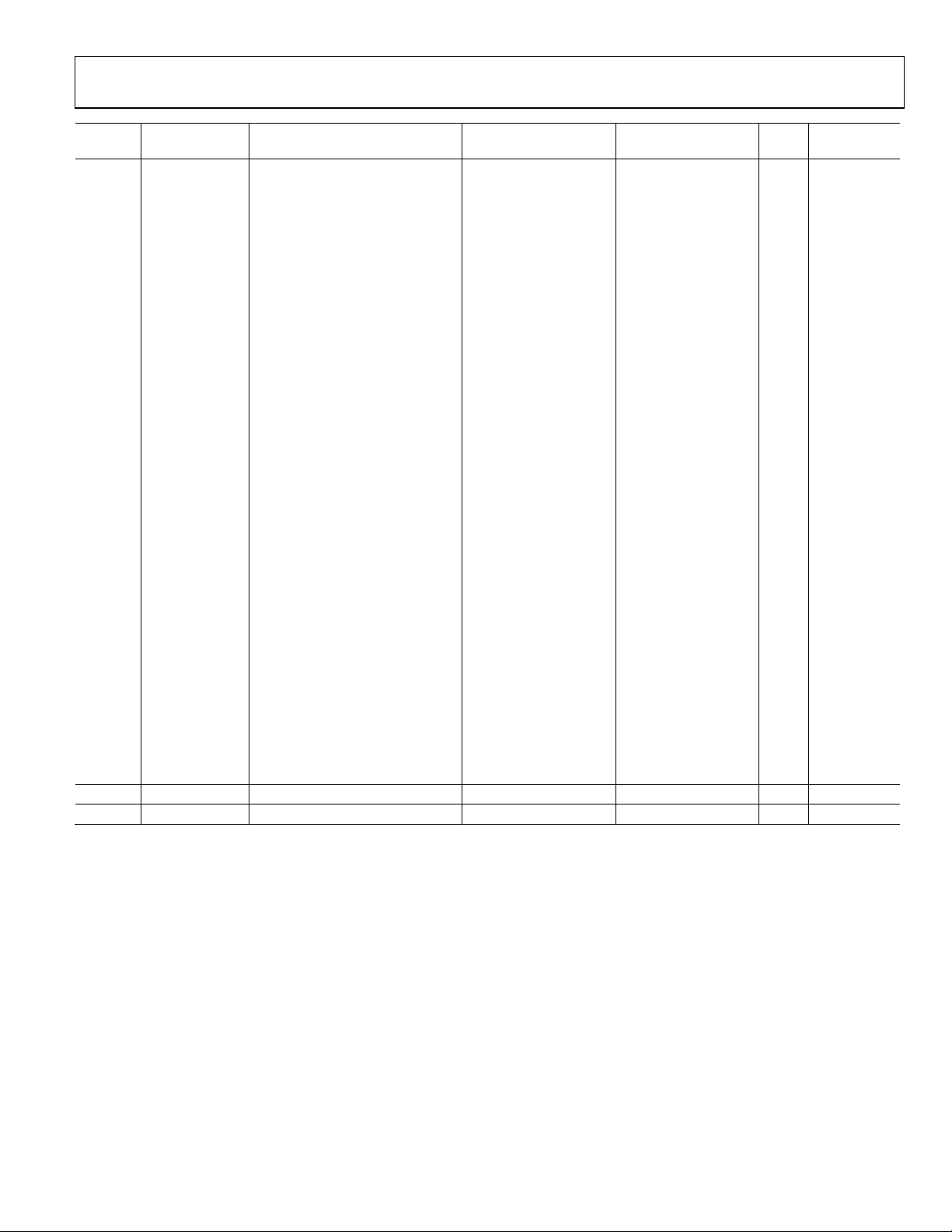
Evaluation Board User Guide UG-030
Sample Rate
Address Cell Name Parameter Name Default Value Function Bytes
0x00F1 HighPass_Comp PeakDBCompLUTAlgPG31tab 0x00, 0x1D, 0xC7, 0xFA, REC_Manual: 132 No
0x00F2 0x00, 0x1F, 0xA6, 0x78, compressor
0x00F3 0x00, 0x24, 0xCD, 0xBF, curve points
0x00F4 0x00, 0x2D, 0xB0, 0xDE,
0x00F5 0x00, 0x3A, 0x4E, 0x7F,
0x00F6 0x00, 0x47, 0xE3, 0x23,
0x00F7 0x00, 0x67, 0x41, 0xE8,
0x00F8 0x00, 0xA1, 0x64, 0x8B,
0x00F9 0x00, 0xF3, 0x71, 0x72,
0x00FA 0x01, 0x4B, 0x5C, 0x80,
0x00FB 0x01, 0x96, 0x84, 0x19,
0x00FC 0x01, 0xF9, 0x0D, 0x62,
0x00FD 0x02, 0x8A, 0xA7, 0xCA,
0x00FE 0x03, 0x24, 0x67, 0xA2,
0x00FF 0x03, 0x9A, 0x7A, 0x83,
0x0100 0x03, 0xD1, 0x34, 0x62,
0x0101 0x03, 0xA2, 0xBD, 0x15,
0x0102 0x03, 0x3D, 0x07, 0x65,
0x0103 0x02, 0xC9, 0xE3, 0xC3,
0x0104 0x02, 0x4D, 0x52, 0x70,
0x0105 0x01, 0xCE, 0xBA, 0xD0,
0x0106 0x01, 0x5C, 0x48, 0xE1,
0x0107 0x00, 0xFF, 0x34, 0xC9,
0x0108 0x00, 0xB8, 0x8A, 0x49,
0x0109 0x00, 0x83, 0xA5, 0x3C,
0x010A 0x00, 0x5D, 0x40, 0x76,
0x010B 0x00, 0x42, 0x04, 0x69,
0x010C 0x00, 0x2E, 0xBC, 0x93,
0x010D 0x00, 0x21, 0x16, 0x45,
0x010E 0x00, 0x17, 0x65, 0x63,
0x010F 0x00, 0x10, 0x8B, 0x23,
0x0110 0x00, 0x0B, 0xB2, 0xB1,
0x0111 0x00, 0x08, 0x45, 0x91
0x0112 HighPass_Comp PeakDBCompLUTAlgPG32decay 0x00, 0x00, 0x00, 0xB6 Speaker: decay 4 Yes
0x0113 HighPass_Comp PeakDBCompLUTAlgPG32hold 0x00, 0x00, 0x00, 0xF0 Speaker: hold 4 Yes
Dependent?
Rev. 0 | Page 35 of 40
Page 36
UG-030 Evaluation Board User Guide
Sample Rate
Address Cell Name Parameter Name Default Value Function Bytes
0x0114 HighPass_Comp PeakDBCompLUTAlgPG32tab 0x00, 0x80, 0x00, 0x00, Speaker: 132 No
0x0115 0x00, 0x80, 0x00, 0x00, compressor
0x0116 0x00, 0x80, 0x00, 0x00, curve points
0x0117 0x00, 0x80, 0x00, 0x00,
0x0118 0x00, 0x80, 0x00, 0x00,
0x0119 0x00, 0x80, 0x00, 0x00,
0x011A 0x00, 0x80, 0x00, 0x00,
0x011B 0x00, 0x80, 0x00, 0x00,
0x011C 0x00, 0x80, 0x00, 0x00,
0x011D 0x00, 0x80, 0x00, 0x00,
0x011E 0x00, 0x80, 0x00, 0x00,
0x011F 0x00, 0x80, 0x00, 0x00,
0x0120 0x00, 0x80, 0x00, 0x00,
0x0121 0x00, 0x80, 0x00, 0x00,
0x0122 0x00, 0x80, 0x00, 0x00,
0x0123 0x00, 0x80, 0x00, 0x00,
0x0124 0x00, 0x80, 0x00, 0x00,
0x0125 0x00, 0x80, 0x00, 0x00,
0x0126 0x00, 0x80, 0x00, 0x00,
0x0127 0x00, 0x80, 0x00, 0x00,
0x0128 0x00, 0x80, 0x00, 0x00,
0x0129 0x00, 0x80, 0x00, 0x00,
0x012A 0x00, 0x7F, 0xF0, 0x61,
0x012B 0x00, 0x7D, 0x6C, 0x21,
0x012C 0x00, 0x75, 0x7A, 0x64,
0x012D 0x00, 0x68, 0xDB, 0x84,
0x012E 0x00, 0x5A, 0x4C, 0x32,
0x012F 0x00, 0x4C, 0x3E, 0xA8,
0x0130 0x00, 0x40, 0x26, 0xE7,
0x0131 0x00, 0x2D, 0x5C, 0xBF,
0x0132 0x00, 0x20, 0x13, 0x74,
0x0133 0x00, 0x16, 0xAE, 0x60,
0x0134 0x00, 0x10, 0x09, 0xBA
0x0138 HighPass_Comp PeakDBCompLUTAlgPG30post_gain 0x00, 0x80, 0x00, 0x00 REC_Auto: post gain 4 No
0x0139 HighPass_Comp PeakDBCompLUTAlgPG31post_gain 0x00, 0x80, 0x00, 0x00 REC_Manual: post gain 4 No
0x013A HighPass_Comp PeakDBCompLUTAlgPG32post_gain 0x00, 0x80, 0x00, 0x00 Speaker: post gain 4 No
0x0140 LowPass_Comp PeakDBCompLUTAlgPG40decay 0x00, 0x00, 0x00, 0x04 REC_Auto: decay 4 Yes
0x0141 LowPass_Comp PeakDBCompLUTAlgPG40hold 0x00, 0x00, 0x00, 0x60 REC_Auto: hold 4 Yes
Dependent?
Rev. 0 | Page 36 of 40
Page 37

Evaluation Board User Guide UG-030
Sample Rate
Address Cell Name Parameter Name Default Value Function Bytes
0x0142 LowPass_Comp PeakDBCompLUTAlgPG40tab 0x00, 0x05, 0x1A, 0x96, REC_Auto: 132 No
0x0143 0x00, 0x04, 0xB6, 0x9B, compressor
0x0144 0x00, 0x04, 0xAD, 0x54, cu rve points
0x0145 0x00, 0x05, 0x55, 0x55,
0x0146 0x00, 0x08, 0x55, 0xC1,
0x0147 0x00, 0x11, 0x6C, 0xA5,
0x0148 0x00, 0x25, 0x0E, 0xD2,
0x0149 0x00, 0x4D, 0x9C, 0x93,
0x014A 0x00, 0xA0, 0x10, 0xF5,
0x014B 0x01, 0x46, 0xB2, 0x33,
0x014C 0x02, 0x80, 0x9F, 0x0A,
0x014D 0x03, 0xF0, 0xCE, 0x62,
0x014E 0x05, 0x54, 0x59, 0xF2,
0x014F 0x05, 0xEF, 0xF5, 0xFC,
0x0150 0x05, 0xBA, 0x65, 0x98,
0x0151 0x05, 0x17, 0xAD, 0xEF,
0x0152 0x04, 0x3A, 0x77, 0xC5,
0x0153 0x03, 0x56, 0xDC, 0x88,
0x0154 0x02, 0x8B, 0x2A, 0xC5,
0x0155 0x01, 0xE7, 0x60, 0xA5,
0x0156 0x01, 0x67, 0x06, 0x39,
0x0157 0x01, 0x05, 0xD8, 0x28,
0x0158 0x00, 0xBE, 0x7E, 0xE5,
0x0159 0x00, 0x8A, 0x46, 0xF6,
0x015A 0x00, 0x64, 0x17, 0x5B,
0x015B 0x00, 0x48, 0x3E, 0xCA,
0x015C 0x00, 0x34, 0x06, 0x48,
0x015D 0x00, 0x25, 0x6A, 0x11,
0x015E 0x00, 0x1A, 0xE6, 0xE6,
0x015F 0x00, 0x13, 0x05, 0xC6,
0x0160 0x00, 0x0D, 0x73, 0x73,
0x0161 0x00, 0x09, 0x82, 0xE3,
0x0162 0x00, 0x06, 0xB9, 0xBA
0x0163 LowPass_Comp PeakDBCompLUTAlgPG41decay 0x00, 0x00, 0x00, 0x12 REC_Manual: decay 4 Yes
0x0164 LowPass_Comp PeakDBCompLUTAlgPG41hold 0x00, 0x00, 0x01, 0xE0 REC_Manual: hold 4 Yes
Dependent?
Rev. 0 | Page 37 of 40
Page 38
UG-030 Evaluation Board User Guide
Sample Rate
Address Cell Name Parameter Name Default Value Function Bytes
0x0165 LowPass_Comp PeakDBCompLUTAlgPG41tab 0x00, 0x1D, 0xC7, 0xFA, REC_Manual: 132 No
0x0166 0x00, 0x1F, 0xA6, 0x78, compressor
0x0167 0x00, 0x24, 0xCD, 0xBF, curve points
0x0168 0x00, 0x2D, 0xB0, 0xDE,
0x0169 0x00, 0x3A, 0x4E, 0x7F,
0x016A 0x00, 0x47, 0xE3, 0x23,
0x016B 0x00, 0x67, 0x41, 0xE8,
0x016C 0x00, 0xA1, 0x64, 0x8B,
0x016D 0x00, 0xF3, 0x71, 0x72,
0x016E 0x01, 0x4B, 0x5C, 0x80,
0x016F 0x01, 0x96, 0x84, 0x19,
0x0170 0x01, 0xF9, 0x0D, 0x62,
0x0171 0x02, 0x8A, 0xA7, 0xCA,
0x0172 0x03, 0x24, 0x67, 0xA2,
0x0173 0x03, 0x9A, 0x7A, 0x83,
0x0174 0x03, 0xD1, 0x34, 0x62,
0x0175 0x03, 0xA2, 0xBD, 0x15,
0x0176 0x03, 0x3D, 0x07, 0x65,
0x0177 0x02, 0xC9, 0xE3, 0xC3,
0x0178 0x02, 0x4D, 0x52, 0x70,
0x0179 0x01, 0xCE, 0xBA, 0xD0,
0x017A 0x01, 0x5C, 0x48, 0xE1,
0x017B 0x00, 0xFF, 0x34, 0xC9,
0x017C 0x00, 0xB8, 0x8A, 0x49,
0x017D 0x00, 0x83, 0xA5, 0x3C,
0x017E 0x00, 0x5D, 0x40, 0x76,
0x017F 0x00, 0x42, 0x04, 0x69,
0x0180 0x00, 0x2E, 0xBC, 0x93,
0x0181 0x00, 0x21, 0x16, 0x45,
0x0182 0x00, 0x17, 0x65, 0x63,
0x0183 0x00, 0x10, 0x8B, 0x23,
0x0184 0x00, 0x0B, 0xB2, 0xB1,
0x0185 0x00, 0x08, 0x45, 0x91
0x0186 LowPass_Comp PeakDBCompLUTAlgPG42decay 0x00, 0x00, 0x00, 0xB6 Speaker: decay 4 Yes
0x0187 LowPass_Comp PeakDBCompLUTAlgPG42hold 0x00, 0x00, 0x00, 0xF0 Speaker: hold 4 Yes
Dependent?
Rev. 0 | Page 38 of 40
Page 39

Evaluation Board User Guide UG-030
Sample Rate
Address Cell Name Parameter Name Default Value Function Bytes
0x0188 LowPass_Comp PeakDBCompLUTAlgPG42tab 0x00, 0x80, 0x00, 0x00, Speaker: 132 No
0x0189 0x00, 0x80, 0x00, 0x00, compressor
0x018A 0x00, 0x80, 0x00, 0x00, curve points
0x018B 0x00, 0x80, 0x00, 0x00,
0x018C 0x00, 0x80, 0x00, 0x00,
0x018D 0x00, 0x80, 0x00, 0x00,
0x018E 0x00, 0x80, 0x00, 0x00,
0x018F 0x00, 0x80, 0x00, 0x00,
0x0190 0x00, 0x80, 0x00, 0x00,
0x0191 0x00, 0x80, 0x00, 0x00,
0x0192 0x00, 0x80, 0x00, 0x00,
0x0193 0x00, 0x80, 0x00, 0x00,
0x0194 0x00, 0x80, 0x00, 0x00,
0x0195 0x00, 0x80, 0x00, 0x00,
0x0196 0x00, 0x80, 0x00, 0x00,
0x0197 0x00, 0x80, 0x00, 0x00,
0x0198 0x00, 0x80, 0x00, 0x00,
0x0199 0x00, 0x80, 0x00, 0x00,
0x019A 0x00, 0x80, 0x00, 0x00,
0x019B 0x00, 0x80, 0x00, 0x00,
0x019C 0x00, 0x80, 0x00, 0x00,
0x019D 0x00, 0x80, 0x00, 0x00,
0x019E 0x00, 0x7F, 0xF0, 0x61,
0x019F 0x00, 0x7D, 0x6C, 0x21,
0x01A0 0x00, 0x75, 0x7A, 0x64,
0x01A1 0x00, 0x68, 0xDB, 0x84,
0x01A2 0x00, 0x5A, 0x4C, 0x32,
0x01A3 0x00, 0x4C, 0x3E, 0xA8,
0x01A4 0x00, 0x40, 0x26, 0xE7,
0x01A5 0x00, 0x2D, 0x5C, 0xBF,
0x01A6 0x00, 0x20, 0x13, 0x74,
0x01A7 0x00, 0x16, 0xAE, 0x60,
0x01A8 0x00, 0x10, 0x09, 0xBA
0x01AC LowPass_Comp PeakDBCompLUTAlgPG40post_gain 0x00, 0x80, 0x00, 0x00 REC_Auto: post gain 4 No
0x01AD LowPass_Comp PeakDBCompLUTAlgPG41post_gain 0x00, 0x80, 0x00, 0x00 REC_Manual: post gain 4 No
0x01AE LowPass_Comp PeakDBCompLUTAlgPG42post_gain 0x00, 0x80, 0x00, 0x00 Speaker: post gain 4 No
0x01B4 compS stereomux1940ns50 0x00, 0x00, 0x00, 0x00
0x01B5 compS stereomux1940ns51 0x00, 0x80, 0x00, 0x00
On/off (burst write
Address 0x01B4 and
Address 0x01B5
together)
On/off (burst write
Address 0x01B4 and
Address 0x01B5
together)
4 No
4 No
Dependent?
Rev. 0 | Page 39 of 40
Page 40

UG-030 Evaluation Board User Guide
Sample Rate
Address Cell Name Parameter Name Default Value Function Bytes
0x01B6 dmute MuteSWLinSlewAlg1mute 0x00, 0x00, 0x00, 0x00
Mute digital (record)
4 No
output
0x01B7 dmute MuteSWLinSlewAlg1step 0x00, 0x00, 0x40, 0x00
Slew rate for
4 Yes
digital mute
0x01B8 slewvol GainS200AlgGrow1gain_target 0x00, 0x80, 0x00, 0x00
Analog output
4 No
volume control
0x01BA amute MuteSWLinSlewAlg2mute 0x00, 0x00, 0x00, 0x00
Mute analog
4 No
(playback) output
0x01BB amute MuteSWLinSlewAlg2step 0x00, 0x00, 0x40, 0x00
Slew rate for
4 Yes
analog mute
0x07FA slewvol GainS200AlgGrow1alpha 0x00, 0x7F, 0xF2, 0x59, Slew rate for analog 8 Yes
0x07FB 0x00, 0x00, 0x0D, 0xA7 volume control
Dependent?
Evaluation boards are only intended for device evaluation and not for production purposes. Evaluation boards are supplied “as is” and without warranties of any kind, express,
implied, or statutory including, but not limited to, any implied warranty of merchantability or fitness for a particular purpose. No license is granted by implication or otherwise under
any patents or other intellectual property by application or use of evaluation boards. Information furnished by Analog Devices is believed to be accurate and reliable. However, no
responsibility is assumed by Analog Devices for its use, nor for any infringements of patents or other rights of third parties that may result from its use. Analog Devices reserves the
right to change devices or specifications at any time without notice. Trademarks and registered trademarks are the property of their respective owners. Evaluation boards are not
authorized to be used in life support devices or systems.
©2009 Analog Devices, Inc. All rights reserved. Trademarks and
registered trademarks are the property of their respective owners.
UG08356-0-11/09(0)
Rev. 0 | Page 40 of 40
 Loading...