

Page 1
2936-120
3-PHASE BRUSHLESS DC MOTOR
CONTROLLER/DRIVER
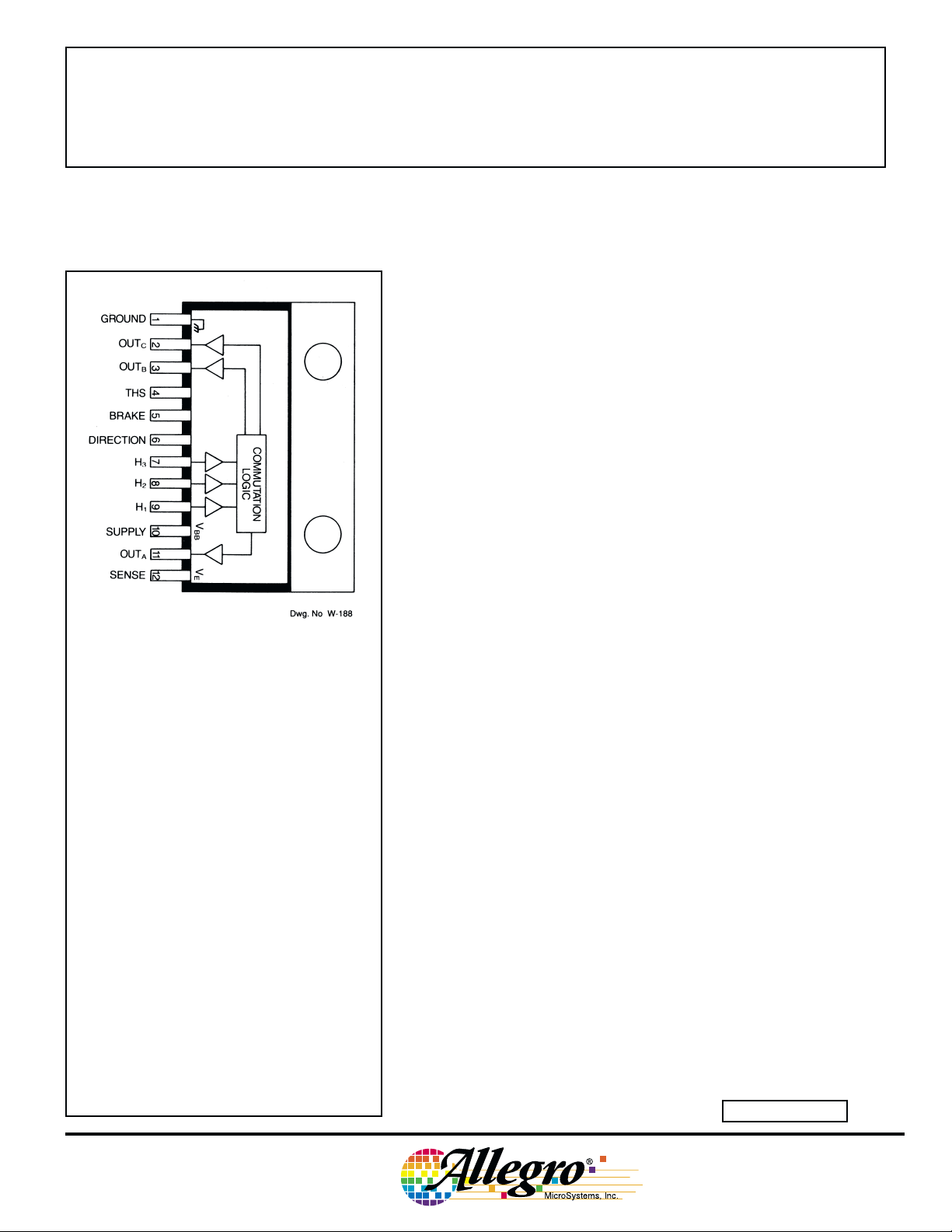
Combining logic and power, the UDN2936W-120 provides com-
mutation and drive for three-phase brushless dc motors. Each of the
three outputs are rated at 45 V and ±2 A (±3 A peak), and include
internal ground clamp and flyback diodes. The driver also features
internal commutation logic, PWM current control, and thermal shutdown protection.
The UDN2936W-120 is compatible with single-ended digital or
linear Hall effect sensors. The commutating logic is programmed for
120° electrical separation. The UDN2936W-120 can replace the
original UDN2936W (60° electrical separation) by simply adding an
inverter at the H
current through an external sense resistor and pulse-width modulating
the source drivers. Voltage thresholds and hysteresis can be externally
set by the user. If desired, internal threshold and hysteresis defaults
(300 mV, 7.5 percent) can be used. The UDN2936W-120 also includes
braking and direction control. Internal protection circuitry prevents
crossover current when braking or changing direction.
input. Current control is accomplished by sensing
2
Data Sheet
29318.20B
ABSOLUTE MAXIMUM RATINGS
at TJ ≤ +150°C
Supply Voltage, VBB . . . . . . . . . . . . . . . 45 V
Output Current, I
(continuous) . . . . . . . . . . . . . . . . ±2.0 A
(peak). . . . . . . . . . . . . . . . . . . . .
Input Voltage Range, VIN . . . -0.3 V to 15 V
Threshold Voltage, V
Package Power Dissipation,
. . . . . . . . . . . . . . . . . . . See Graph
P
D
Operating Temperature Range,
. . . . . . . . . . . . . . . . -20°C to +85°C
T
A
Storage Temperature Range,
. . . . . . . . . . . . . . . . -55°C to +150°C
T
S
Note: Output current rating may be limited by
duty cycle, ambient temperature, and heat
sinking. Under any set of conditions, do not
exceed the specified peak current and a junction
temperature of +150°C.
OUT
. . . . . . . . . . . . 15 V
THS
±3.0 A
The UDN2936W-120 is also available for operation between -40°C
and +85°C. To order, change the prefix from ‘UDN’ to ‘UDQ’.
For maximum power-handling capability, the UDN2936W-120 is
supplied in 12-pin single in-line power-tab package. An external heat
sink may be required for high-current applications. The tab is at
ground potential and needs no insulation.
FEATURES
■ 10 V to 45 V Operation
■ ±3 A Peak Output Current
■ Internal Clamp Diodes
■ Internal PWM Current Control
■ 120° Commutation Decoding Logic
■ Thermal Shutdown Protection
■ Compatible with Single-Ended or Differential Hall-Effect Sensors
■ Braking and Direction Control
Always order by complete part number, e.g., UDN2936W-120 .
Page 2
2936-120
3-PHASE BRUSHLESS
DC MOTOR
CONTROLLER/DRIVER
Functional Block Diagram
115 Northeast Cutoff, Box 15036
W
Worcester, Massachusetts 01615-0036 (508) 853-5000
Copyright © 1985, 2000 Allegro MicroSystems, Inc.
Page 3
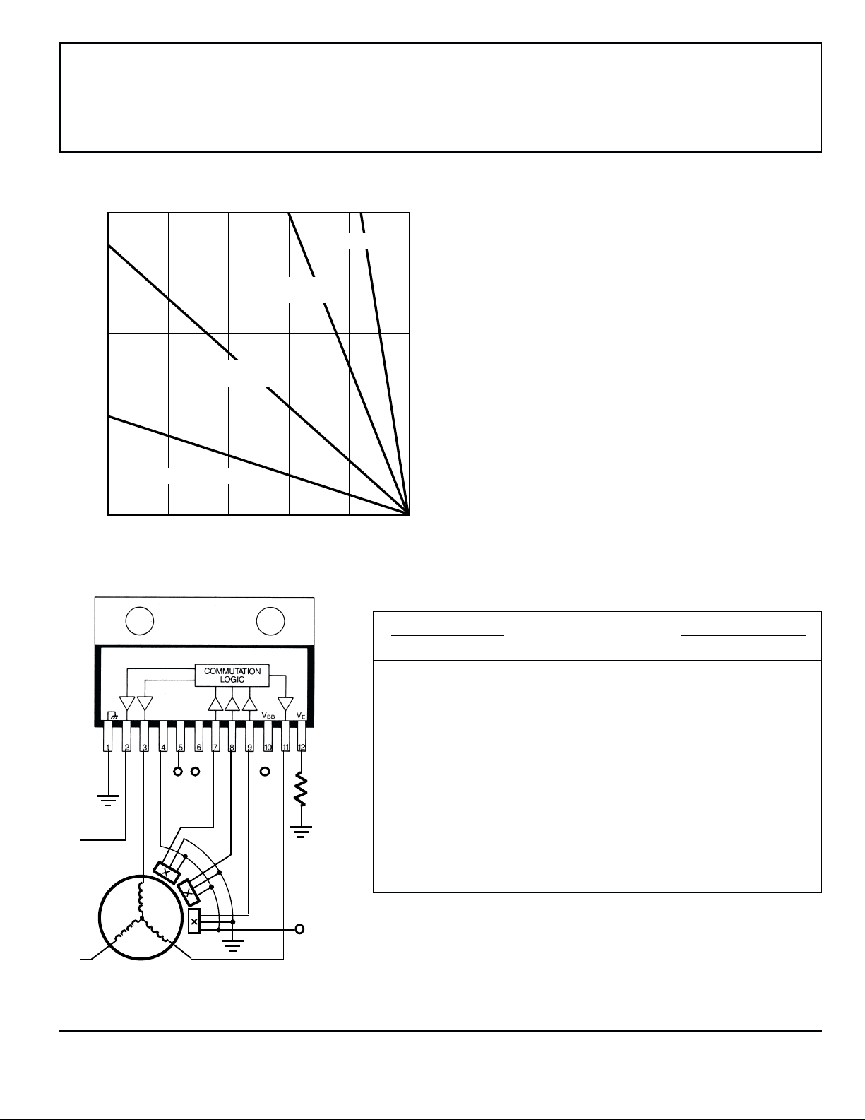
10
R = 2.0°C/W
θJT
2936-120
3-PHASE BRUSHLESS
DC MOTOR
CONTROLLER/DRIVER
8
6
12°C/W HEAT SINK
4
2
FREE AIR, R = 38°C/W
0
ALLOWABLE PACKAGE POWER DISSIPATION IN WATTS
25
50 75 100 125 150
TEMPERATURE IN °C
3.0°C/W HEAT SINK
R = 14°C/W
θJA
θJA
R = 5.0°C/W
θJA
Typical Application
R =
S
0.15 Ω
DIR.
BRAKE
BB
V
Dwg. GP-012B
Commutation Truth Table
UDN2936W-120
Hall Sensor Inputs Outputs
H
H
1
High Low High Low High Z Low High
High Low Low Low High High Low Z
High High Low Low High High Z Low
Low High Low Low High Z High Low
Low High High Low High Low High Z
Low Low High Low High Low Z High
High Low High High High Z High Low
High Low Low High High Low High Z
High High Low High High Low Z High
Low High Low High High Z Low High
Low High High High High High Low Z
Low Low High High High High Z Low
X X X X Low Low Low Low
H3 DIRECTION BRAKE OUTAOUTB OUT
2
C
www.allegromicro.com
V
CC
Dwg. EP-033
X= Irrelevant
Z = High Impedance
Note that the UDN2936W-120 truth table is the same as the original
UDN2936W except that the H
Hall sensor inputs are inverted.
2
Page 4

2936-120
3-PHASE BRUSHLESS
DC MOTOR
CONTROLLER/DRIVER
ELECTRICAL CHARACTERISTICS at TA = +25°C, TJ ≤ +150°C, VBB = 45 V
Limits
Characteristic Symbol Test Conditions Min. Typ. Max. Units
Supply Voltage Range V
Supply Current I
Thermal Shutdown Temp. T
Thermal Shutdown Hysteresis ∆T
Output Drivers
Output Leakage Current I
Output Saturation Voltage V
Output Sustaining Voltage V
CEX
CE(SAT)
CE(sus)
Clamp Diode Forward Voltage V
Clamp Diode Leakage Current I
Output Switching Time t
Turn-ON Delay t
(Resistive Load)
BB
t
on
BB
J
J
F
R
r
f
Operating 10 — 45 V
Outputs Open — 32 40 mA
V
= 0.8 V — 42 50 mA
BRAKE
— 165 — °C
—25 — °C
V
= V
V
I
OUT
I
OUT
I
OUT
I
OUT
I
OUT
OUT
OUT
BB
= 0 V — — -50 µA
= -1 A — 1.7 1.9 V
= +1 A — 1.1 1.3 V
= -2 A — 1.9 2.1 V
= +2 A — 1.4 1.6 V
= ±2 A, L = 2 mH 45 — — V
—— 50 µA
IF = 2 A — 1.8 2.0 V
VR = 45 V — — 50 µA
I
= ±2 A, Resistive Load — 2.0 — µs
OUT
I
= ±2 A, Resistive Load — 2.0 — µs
OUT
Source Drivers, 0 to -2 A — 1.25 — µs
Sink Drivers, 0 to +2 A — 1.9 — µs
Turn-OFF Delay t
(Resistive Load)
off
Source Drivers, -2 A to 0 — 1.7 — µs
Sink Drivers, +2 A to 0 — 0.9 — µs
Continued next page...
115 Northeast Cutoff, Box 15036
Worcester, Massachusetts 01615-0036 (508) 853-5000
Page 5

2936-120
3-PHASE BRUSHLESS
DC MOTOR
CONTROLLER/DRIVER
ELECTRICAL CHARACTERISTICS at TA = +25°C, TJ ≤ +150°C, VBB = 45 V continued
Limits
Characteristic Symbol Test Conditions Min. Typ. Max. Units
Control Logic
Logic lnput Voltage V
Sensor lnput Voltage Threshold V
Input Current I
V
I
IN(1)
IN(0)
IN(1)
IN(0)
I
THS
IN
Current Limit Threshold —
Default Sense Trip Voltage V
SENSE
Default Hysteresis — V
Deadtime t
d
V
or V
DIR
V
DIR
H1, H2, or H
V
DIR
V
BRAKE
BRAKE
or V
BRAKE
3
= 2 V — 150 200 µA
= 2 V — <1.0 5.0 µA
2.0 — — V
——0.8 V
—2.5 — V
VH = 5 V — -190 -220 µA
V
= 0.8 V — 35 50 µA
DIR
V
= 0.8 V — -5.0 -20 µA
BRAKE
VH = 0.8 V — -0.64 -1.0 mA
V
≥ 3.0 V — -8.0 -15 µA
THS
V
< 3.0 V, V
THS
V
< 3.0 V, V
THS
V
THS/VSENSE
V
THS
THS
at trip point, V
≥ 3.0 V 270 300 330 mV
≥ 3.0 V — 7.5 — %
SENSE
SENSE
< V
> V
/10.5 — -15 -30 µA
THS
/9.5 190 250 310 µA
THS
< 3.0 V
THS
9.5 10 10.5 —
BRAKE or DIRECTION — 2.0 — µs
www.allegromicro.com
Page 6

2936-120
3-PHASE BRUSHLESS
DC MOTOR
CONTROLLER/DRIVER
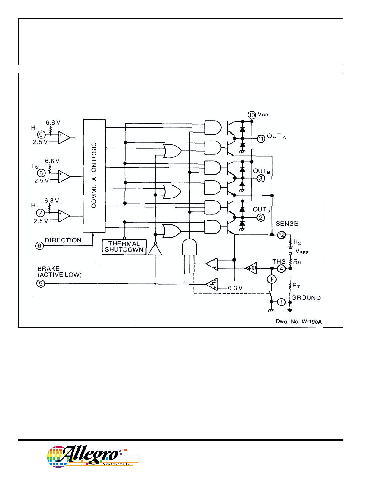
APPLICATIONS INFORMATION
The UDN2936W-120 power driver provides commutation
logic and power outputs to drive three-phase brushless dc
motors.
The UDN2936W-120 is designed to interface with singleended linear or digital Hall-effect devices (HEDs). Internal
pull-up resistors allow for direct use with open-collector digital
HEDs. The Hn inputs have 2.5 V thresholds.
The commutation logic provides decoding for HEDs with
120° electrical separation. At any one step in the logic sequencing, one half-bridge driver is sourcing current, one driver is
sinking current, and one driver is in a high-impedance state (see
Truth Table).
A logic low on the BRAKE pin turns on the three sink
drivers and turns off the three source drivers, essentially
shorting the motor windings to ground. During braking, the
back-electromotive force generated by the motor produces a
current that dynamically brakes the motor. Depending upon the
rotational velocity of the motor, this current can approach the
locked rotor current level (which is limited only by the motor
winding resistance). During braking, the output currentlimiting circuitry is disabled and care should be taken to ensure
that the back-EMF generated brake current does not exceed the
maximum rating (3 A peak) of the sink drivers and ground
clamp diodes.
Changing the logic level of the DIRECTION pin inverts the
output states, thus reversing the direction of the motor. Changing the direction of a rotating motor produces a back-EMF
current similar to when braking the motor. The load current
should not be allowed to exceed the maximum rating (±3 A
peak) of the drivers.
Thresholds and hysteresis can be set with external resistors,
or internal defaults can be used. With V
> 3.0 V, the trip
THS
point is internally set at 300 mV with 7.5% hysteresis. Load
current is then determined by the equation:
I
= 0.3 /R
With V
TRIP
< 3.0 V, the threshold, hysteresis percentage,
THS
S
and peak current are set with external resistors according to the
equations:
threshold voltage (V
hysteresis percentage = RH/50 V
load trip current (I
THS
) = V
TRIP
x RT /(RH + RT)
REF
) = V
THS
/10 R
REF
S
Percentage hysteresis is a fixed value independent of load
current. The chopping frequency is a function of circuit
parameters including load inductance, load resistance, supply
voltage, hysteresis, and switching speed of the drivers.
The UDN2936W-120 outputs are rated for normal operating currents of up to ±2 A and startup currents to ±3 A (see
cautions above regarding braking and changing of motor
direction). Internal power ground-clamp and flyback diodes
protect the outputs from the voltage transients that occur when
switching inductive loads. All devices also feature thermal
protection circuitry. If the junction temperature reaches
+165°C, the thermal shutdown circuitry turns off all output
drivers. The outputs are re-enabled when the junction cools
down to approximately +140°C. This protection is only
intended to protect the device from failures due to excessive
junction temperature or loss of heat sinking and should not
imply that output short circuits are permitted.
An internally generated dead time (td) of approximately
2 µs prevents potentially destructive crossover currents that can
occur when changing direction or braking.
Motor current is internally controlled by pulse-width
modulating the source drivers with a preset hysteresis format.
Load current through an external sense resistor (RS) is constantly monitored. When the current reaches the set trip point
(determined by an external reference voltage or internal
default), the source driver is disabled. Current recirculates
through the ground clamp diode, motor winding, and sink
driver. An internal constant-current sink reduces the trip point
(hysteresis). When the decaying current reaches this lower
threshold, the source driver is enabled again and the cycle
repeats.
115 Northeast Cutoff, Box 15036
Worcester, Massachusetts 01615-0036 (508) 853-5000
As with all high-power integrated circuits, the printed
wiring board should utilize a heavy ground plane. For optimum
performance, the drivers should be soldered directly into the
board. The power supply should be decoupled with an electrolytic capacitor (>10 µF) as close as possible to the device
supply pin (VBB).
Replacing the UDN2936W. The original UDN2936W can
be easily replaced with a UDN2936W-120 by inserting an
inverter (two resistors and a 2N3904 or 2N2222) between the
H2 Hall sensor and pin 8 of the UDN2936W-120, as shown in
the figure on the next page. If an extra inverter is available, be
certain that a pull-up for the Hall sensor is provided.
Page 7

V
DIRECTION
V
H1
V
H2
V
H3
OUT
A
2936-120
3-PHASE BRUSHLESS
DC MOTOR
CONTROLLER/DRIVER
+
0
–
+
OUT
0
B
–
+
OUT
0
C
–
Replacing the original UDN2936W
+V
+V
SENSOR H2
X
CC
V
CUT
2N2222
OR
2N3904
UDN2936W-120
+6.8 V
8
+2.5 V
+
–
Dwg. EP-071
t
d
Dwg. WM-002-1
Typical Hall-Effect
Sensor Locations
Dwg. No. W-193
www.allegromicro.com
Page 8

2936-120
3-PHASE BRUSHLESS
DC MOTOR
CONTROLLER/DRIVER
Dimensions in Inches
(controlling dimensions)
INDEX
AREA
0.065
0.035
0.020
1.260
1.240
0.775
0.765
0.245
0.225
0.180
0.155
MAX
0.055
0.045
ø
0.145
0.140
0.135
0.570
0.365
1
0.030
0.020
12
0.100
±0.010
0.540
0.290
0.023
0.018
MIN
0.100
0.080
0.070
Dwg. MP-007 in
NOTES: 1. Lead thickness is measured at seating plane or below.
2. Lead spacing tolerance is non-cumulative
3. Exact body and lead configuration at vendor’s option
within limits shown.
4. Lead gauge plane is 0.030” below seating plane.
5. Supplied in standard sticks/tubes of 15 devices.
115 Northeast Cutoff, Box 15036
Worcester, Massachusetts 01615-0036 (508) 853-5000
Page 9

Dimensions in Millimeters
(for reference only)
2936-120
3-PHASE BRUSHLESS
DC MOTOR
CONTROLLER/DRIVER
INDEX
AREA
1.65
0.89
0.51
1
32.00
31.49
19.69
19.45
0.76
0.51
12
6.22
5.71
3.56
9.27
2.54
±0.254
3.94
3.68
4.57
MAX
ø
14.48
13.71
7.36
MIN
0.59
0.45
1.40
1.14
3.43
2.54
2.03
1.77
Dwg. MP-007 mm
The products described here are manufactured
under one or more U.S. patents or U.S. patents
pending.
Allegro MicroSystems, Inc. reserves the right to
make, from time to time, such departures from the detail
specifications as may be required to permit improvements in the performance, reliability, or
manufacturability of its products. Before placing an
order, the user is cautioned to verify that the information being relied upon is current.
Allegro products are not authorized for use as
critical components in life-support devices or systems
without express written approval.
The information included herein is believed to be
accurate and reliable. However, Allegro
MicroSystems, Inc. assumes no responsibility for its
use; nor for any infringement of patents or other rights
of third parties which may result from its use.
www.allegromicro.com
NOTES: 1. Lead thickness is measured at seating plane or below.
2. Lead spacing tolerance is non-cumulative
3. Exact body and lead configuration at vendor’s option
within limits shown.
4. Lead gauge plane is 0.762 mm below seating plane.
5. Supplied in standard sticks/tubes of 15 devices.
Page 10

2936-120
3-PHASE BRUSHLESS
DC MOTOR
CONTROLLER/DRIVER
MOTOR DRIVERS
Function Output Ratings* Part Number
INTEGRATED CIRCUITS FOR BRUSHLESS DC MOTORS
3-Phase Power MOSFET Controller — 28 V 3933
3-Phase Power MOSFET Controller — 50 V 3932
3-Phase Power MOSFET Controller — 50 V 7600
2-Phase Hall-Effect Sensor/Driver 400 mA 26 V 3626
Bidirectional 3-Phase Back-EMF Controller/Driver ±600 mA 14 V 8906
2-Phase Hall-Effect Sensor/Driver 900 mA 14 V 3625
3-Phase Back-EMF Controller/Driver ±900 mA 14 V 8902–A
3-Phase Controller/Driver ±2.0 A 45 V 2936-120
INTEGRATED BRIDGE DRIVERS FOR DC AND BIPOLAR STEPPER MOTORS
Dual Full Bridge with Protection & Diagnostics ±500 mA 30 V 3976
PWM Current-Controlled Dual Full Bridge ±650 mA 30 V 3966
PWM Current-Controlled Dual Full Bridge ±650 mA 30 V 3968
PWM Current-Controlled Dual Full Bridge ±750 mA 45 V 2916
PWM Current-Controlled Dual Full Bridge ±750 mA 45 V 2919
PWM Current-Controlled Dual Full Bridge ±750 mA 45 V 6219
PWM Current-Controlled Dual Full Bridge ±800 mA 33 V 3964
PWM Current-Controlled Dual DMOS Full Bridge ±1.0 A 35 V 3973
PWM Current-Controlled Full Bridge ±1.3 A 50 V 3953
PWM Current-Controlled Dual Full Bridge ±1.5 A 45 V 2917
PWM Current-Controlled Microstepping Full Bridge ±1.5 A 50 V 3955
PWM Current-Controlled Microstepping Full Bridge ±1.5 A 50 V 3957
PWM Current-Controlled Dual DMOS Full Bridge ±1.5 A 50 V 3972
Dual Full-Bridge Driver ±2.0 A 50 V 2998
PWM Current-Controlled Full Bridge ±2.0 A 50 V 3952
DMOS Full Bridge PWM Driver ±2.0 A 50 V 3958
Dual DMOS Full Bridge ±2.5 A 50 V 3971
UNIPOLAR STEPPER MOTOR & OTHER DRIVERS
Voice-Coil Motor Driver ±500 mA 6 V 8932–A
Voice-Coil Motor Driver ±800 mA 16 V 8958
Unipolar Stepper-Motor Quad Drivers 1 A 46 V 7024 & 7029
Unipolar Microstepper-Motor Quad Driver 1.2 A 46 V 7042
Unipolar Stepper-Motor Translator/Driver 1.25 A 50 V 5804
Unipolar Stepper-Motor Quad Driver 1.8 A 50 V 2540
Unipolar Stepper-Motor Quad Driver 1.8 A 50 V 2544
Unipolar Stepper-Motor Quad Driver 3 A 46 V 7026
Unipolar Microstepper-Motor Quad Driver 3 A 46 V 7044
* Current is maximum specified test condition, voltage is maximum rating. See specification for sustaining voltage limits or
over-current protection voltage limits. Negative current is defined as coming out of (sourcing) the output.
† Complete part number includes additional characters to indicate operating temperature range and package style.
Also, see 3175, 3177, 3235, and 3275 Hall-effect sensors for use with brushless dc motors.
†
115 Northeast Cutoff, Box 15036
Worcester, Massachusetts 01615-0036 (508) 853-5000
 Loading...