

Page 1
2943
A
HIGH-CURRENT HALF-BRIDGE MOTOR DRIVER
2943
HIGH-CURRENT
HALF-BRIDGE MOTOR DRIVER
Designed for use as a general-purpose motor driver, the
UDN2943Z half-bridge driver combines high-current sink and source
drivers with logic stages, level shifting, diode transient protection, and
a voltage regulator for single-supply operation. Capable of operating
in extremely harsh environments, this device can withstand high
ambient temperatures, output overloads, and repeated power supply
transient voltages without damage. The driver can be used in pairs for
full-bridge operation, or as triplets in three-phase brushless dc motordrive applications.
The input circuitry is compatible with TTL, low-voltage CMOS,
and NMOS logic. Logic lockout prevents both source and sink drivers
from turning ON simultaneously. Each driver is turned ON by an activelow input, making the UDN2943Z especially desirable in many microprocessor applications. An accidental input open circuit will turn OFF
the corresponding output. The device also provides an internallygenerated dead time to prevent crossover currents during output
switching. Monolithic, space-saving construction offers reliability
unobtainable with discrete components.
Data Sheet
29318.4B
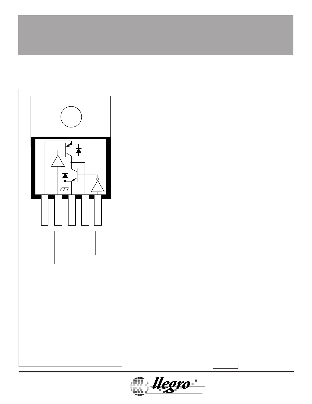
12345
S
+V
OUTPUT
GROUND
SINK INPUT
SOURCE INPUT
DISCONTINUED
ABSOLUTE MAXIMUM RATINGS
Supply Voltage, Range VS.... 8.5 V to 35 V*
Output Voltage, V
Input Voltage Range, V
Continuous Output Current, I
Package Power Dissipation,
P
....................................... See Graph
D
Operating Temperature Range,
T
................................. -20°C to +85°C
A
Storage Temperature Range,
T
............................... -55°C to +150°C
S
*Internal high-voltage shutdown above 24 V.
.......................24 V
CE(sus)
.... -0.3 V to +18 V
IN
— FOR REFERENCE
PRODUCT
Dwg. PP-022-1
...... ±1.0 A
OUT
Saturated output drivers provide for low saturation voltage at the
maximum rated current. Internal short-circuit protection, activated at
load currents above 1 A, protects the source driver from accidental
short-circuits between the output and ground.
The UDN2943Z driver is rated for continuous operation with
inductive loads at supply voltages of up to 24 V. With supply voltage
transients (to 35 V maximum), a high-voltage protection circuit
becomes operative, shutting OFF both output drivers. The internal
thermal shutdown is triggered by a nominal junction temperature
of 160°C.
Single-chip construction and a 5-lead power-tab TS-001 plastic
package provide cost-effective and reliable systems designs.
It also features excellent power dissipation ratings, minimum size, and
ease of installation. The heat-sink tab is at ground potential and does
not require insulation.
ONLY
FEATURES
■ ±1 A Output Current ■ 8.5 V to 24 V Operating Range
■ Saturated Output Drivers ■ Crossover-Current Protected
■ Logic-Compatible Inputs ■ Withstands 35 V Supply Transients
■ Output-Transient Protection ■ Internal Over-Voltage Protection
■ Tri-State Output ■ Internal Short-Circuit Protection
Always order by complete part number: UDQ2943Z .
TM
TM
A
MicroSystems, Inc.
Page 2
2943
A
HIGH-CURRENT HALF-BRIDGE MOTOR DRIVER
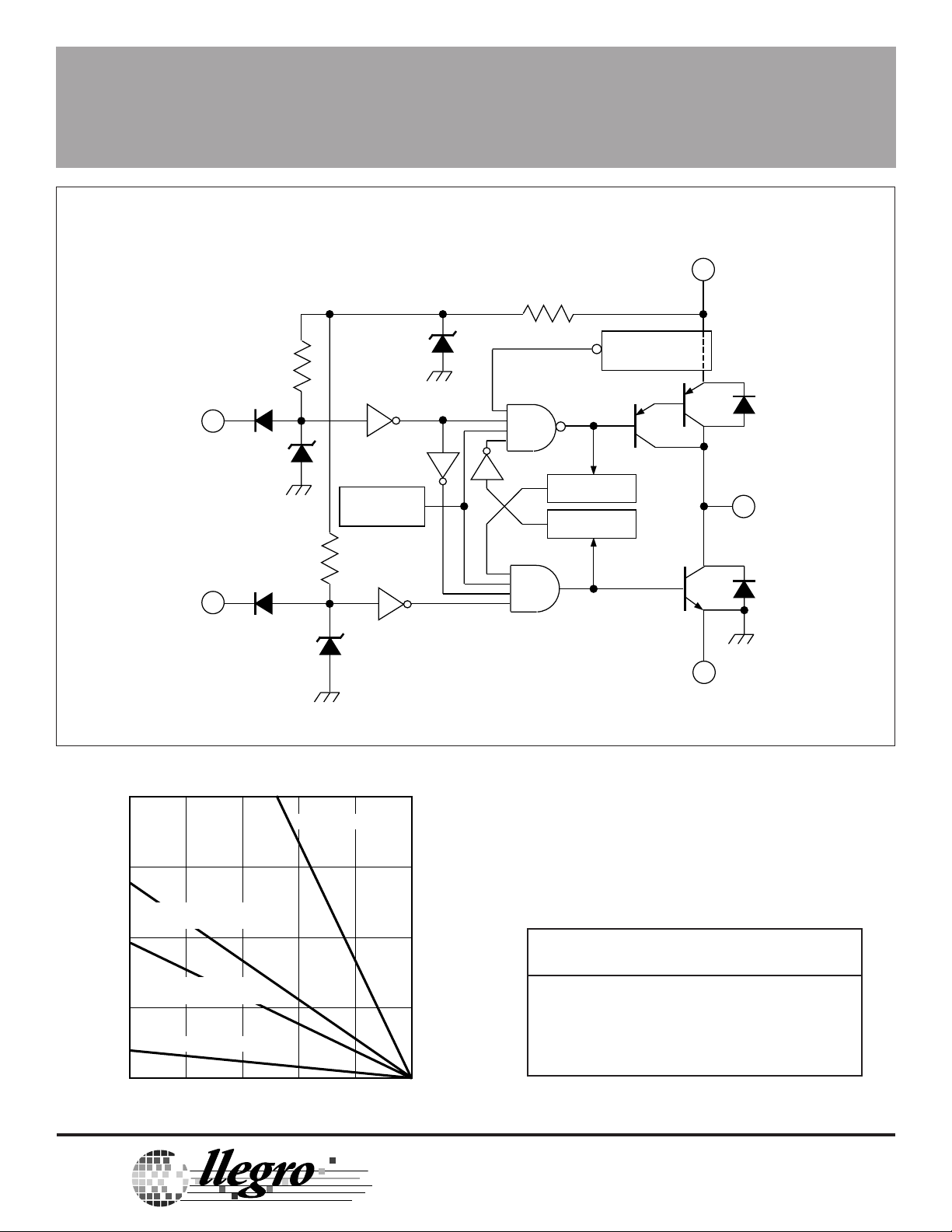
FUNCTIONAL BLOCK DIAGRAM
V
S
1
SOURCE
INPUT
SINK
INPUT
6.35 V
2
2.1 V
OVER-VOLT.
& TSD
5
2.1 V
L-TO-H DELAY
H-TO-L DELAY
HIGH-CURRENT
SENSE
GROUND
OUTPUT
4
3
Dwg. FP-038
20
R = 3.0°C/W
JT
θ
15
AAVID 5071B + 5072B HEAT SINKS,
R = 9.0°C/W
JA
θ
10
STAVER V1-5 HEAT SINK,
R = 13°C/W
JA
θ
5
FREE AIR, R = 65°C/W
0
25
ALLOWABLE PACKAGE POWER DISSIPATION IN WATTS
JA
θ
50 75 100 125 150
TEMPERATURE IN °C
TM
TM
A
MicroSystems, Inc.
Dwg. GP-014A
LOGIC TRUTH TABLE
Source Driver Sink Driver Output
Pin 2 Pin 5 Pin 4
Low Low High
Low High High
High Low Low
High High High Z
115 Northeast Cutoff, Box 15036
Worcester, Massachusetts 01615-0036 (508) 853-5000
115 Northeast Cutoff, Box 15036
Worcester, Massachusetts 01615-0036 (508) 853-5000
Copyright © 1986, 1994, Allegro MicroSystems, Inc.
Page 3

2943
T
T
HIGH-CURRENT HALF-BRIDGE MOTOR DRIVER
ELECTRICAL CHARACTERISTICS at T
= +25°C, V
A
= +24 V (unless otherwise noted).
S
Source Driver Sink Driver Output Limits
Characteristic Symbol Input, Pin 2 Input, Pin 5 Pin 4 Other Min. Typ. Max. Units
Output Leakage Current I
(V
= +35 V) 2.4 V 2.4 V 35 V — — 10 100 µA
S
Output Sustaining Voltage V
CEX
CE(sus)
2.4 V 2.4 V 0 V — — -10 -100 µA
2.4 V 0.8 to 2.4 V 1.0 A Fig. 1A 24 — — V
0.8 to 2.4 V 2.4 V -1.0 A Fig. 1B 24 — — V
Output Saturation Voltage V
CE(SAT)
0.8 V 2.4 V -1.0 A — — 1.2 1.8 V
2.4 V 0.8 V 1.0 A — — 0.6 1.0 V
Short-Circuit Source Current I
Logic Input Voltage V
V
Input Current I
I
Clamp Diode Forward Voltage V
Logic Supply Current I
SC
IN(1)
IN(0)
IN(1)
IN(0)
F
S
0.8 V 2.4 V 0 V — 1.0 — 1.8 A
— — ——2.0——V
— — ————0.8V
2.4 V 2.4 V NC — — 10 100 µA
0.8 V 0.8 V NC — — -50 -200 µA
NC NC 1.0 A Fig. 2 — 1.5 2.0 V
2.4 V 2.4 V NC — — 15 30 mA
2.4 V 0.8 V NC — — 55 75 mA
0.8 V 2.4 V NC — — 30 40 mA
Thermal Shutdown Temperature T
Over-Voltage Shutdown V
Propagation Delay t
J
S
PD
— — ———160—°C
————24—35V
2.4 V 2.4 V to 0.8 V 0.4 A Fig. 3 — 0.6 — µs
0.8 to 2.4 V 2.4 V -0.4 A Fig. 4 — 1.0 — µs
2.4 V 0.8 to 2.4 V 0.4 A Fig. 3 — 1.1 — µs
2.4 to 0.8 V 2.4 V -0.4 A Fig. 4 — 0.6 — µs
Notes: Negative current is defined as coming out of (sourcing) the specified device pin.
Typical Data is for design information only.
SOURCE INPUT
VOLTAGE
SINK INPUT
VOLTAGE
+
OUTPUT
0
CURRENT
–
SINKING CURREN
OPEN CIRCUIT
SOURCING CURREN
Dwg. WP-024
Dwg. WP-024
Page 4

2943
A
HIGH-CURRENT HALF-BRIDGE MOTOR DRIVER
V
S
12 345
2.4 V ∆V
28 mH
I
OUT
Dwg. EP-053
IN
V
S
12 345
I
OUT
2.4 V∆V
28 mH
Dwg. EP-054
IN
Figure 1B
12 345
NC
NC
NC
Dwg. EP-055
Figure 2Figure 1A
V
S
I
F
V
S
A
12 345
2.4 V ∆V
I
OUT
IN
Dwg. EP-056
S
12 345
IN
V
Figure 3 Figure 4
TM
TM
MicroSystems, Inc.
115 Northeast Cutoff, Box 15036
Worcester, Massachusetts 01615-0036 (508) 853-5000
I
OUT
2.4 V∆V
Dwg. EP-057
Page 5

2943
HIGH-CURRENT HALF-BRIDGE MOTOR DRIVER
1.045
0.945
0.539
0.465
0.040
0.020
Dimensions in Inches
0.415
0.390
1 5
0.156
0.139
0.625
0.570
0.067
BSC
O
0.370
0.330
0.025
0.012
0.190
0.165
0.055
0.035
0.115
0.085
26.54
24.00
13.69
11.81
1.01
0.51
Dimensions in Millimeters
(Based on 1" = 25.40 mm)
10.54
9.91
1 5
15.87
14.48
1.70
BSC
3.96
3.53
O
9.39
8.39
0.63
0.31
4.82
4.19
1.39
0.89
2.92
2.16
Dwg. MP-005 in
Dwg. MP-005 mm
Page 6

2943
A
HIGH-CURRENT HALF-BRIDGE MOTOR DRIVER
MOTOR DRIVERS SELECTION GUIDE
Function Output Ratings * Part Number †
INTEGRATED CIRCUITS FOR BRUSHLESS DC MOTORS
3-Phase Controller/Drivers ±2.0 A 45 V 2936 and 2936-120
Hall-Effect Latched Sensors 10 mA 24 V 3175 and 3177
2-Phase Hall-Effect Sensor/Controller 20 mA 25 V 3235
Hall-Effect Complementary Output Sensor 20 mA 25 V 3275
2-Phase Hall-Effect Sensor/Driver 900 mA 14 V 3625
2-Phase Hall-Effect Sensor/Driver 400 mA 26 V 3626
Hall-Effect Comp. Output Sensor/Driver 300 mA 60 V 5275
3-Phase Back-EMF Controller/Driver ±900 mA 14 V 8902–A
3-Phase Controller/DMOS Driver ±4.0 A 14 V 8925
3-Phase Back-EMF Controller/Driver ±1.0 A 7 V 8980 and 8983
INTEGRATED BRIDGE DRIVERS FOR DC AND BIPOLAR STEPPER MOTORS
PWM Current Controlled Dual Full Bridge ±750 mA 45 V 2916
PWM Current Controlled Dual Full Bridge ±1.5 A 45 V 2917
PWM Current Controlled Dual Full Bridge ±1.5 A 45 V 2918
PWM Current Controlled Dual Full Bridge ±750 mA 45 V 2919
Half-Bridge Driver ±1.0 A 24 V 2943
Dual Full Bridge Driver ±2.0 A 50 V 2998
PWM Current Controlled Full Bridge ±2.0 A 50 V 3952
PWM Current Controlled Full Bridge ±1.3 A 50 V 3953
PWM Current Controlled Dual Full Bridge ±800 mA 45 V 3961
PWM Current Controlled Dual Full Bridge ±800 mA 30 V 3962
OTHER INTEGRATED CIRCUIT MOTOR DRIVERS
Unipolar Stepper Motor Quad Driver 1.8 A 50 V 2544
Unipolar Stepper-Motor Translator/Driver 1.25 A 50 V 5804
Unipolar Stepper-Motor Quad Driver 1 A 46 V 7024 and 7029
Unipolar Microstepper-Motor Quad Driver 1.2 A 46 V 7042
Voice-Coil Motor Driver ±500 mA 6 V 8932-A
Voice-Coil Motor Driver ±800 mA 16 V 8958
Voice-Coil (and spindle) Motor Driver ±350 mA 7 V 8980 and 8983
* Current is maximum specified test condition, voltage is maximum rating. See specification for sustaining
voltage limits or over-current protection voltage limits.
Negative current is defined as coming out of (sourcing) the output.
† Complete part number includes additional characters to indicate operating temperature range and package style.
Allegro MicroSystems, Inc. reserves the right to make, from time to time, such departures
from the detail specifications as may be required to permit improvements in the design of its
products. Components made under military approvals will be in accordance with the approval
requirements.
The information included herein is believed to be accurate and reliable. However, Allegro
MicroSystems, Inc. assumes no responsibility for its use; nor for any infringements of patents
or other rights of third parties which may result from its use.
TM
A
TM
MicroSystems, Inc.
115 Northeast Cutoff, Box 15036
Worcester, Massachusetts 01615-0036 (508) 853-5000
 Loading...