

Page 1
2878
AND
2879
QUAD HIGH-CURRENT
DARLINGTON SWITCHES
These quad Darlington arrays are designed to serve as interface
between low-level logic and peripheral power devices such as solenoids, motors, incandescent displays, heaters, and similar loads of up to
320 W per channel. Both integrated circuits include transient-suppression diodes that enable use with inductive loads. The input logic is
compatible with most TTL, DTL, LSTTL, and 5 V CMOS logic.
Type UDN2878W and UDN2879W 4 A arrays are identical except
for output-voltage ratings. The former is rated for operation to 50 V
(35 V sustaining), while the latter has a minimum output breakdown
rating of 80 V (50 V sustaining). The lower-cost UDN2879W-2 is
recommended for applications requiring load currents of 3 A or less.
These less expensive devices are identical to the basic parts except for
the maximum allowable load-current rating.
29305.10B†
Data Sheet
Dwg. No. A-11,974
ABSOLUTE MAXIMUM RATINGS
at +25°C Free-Air Temperature
for any driver
(unless otherwise noted)
Output Voltage, V
(UDN2878W) . . . . . . . . . . . . . . . . 50 V
(UDN2879W & UDN2879W-2) . . 80 V
Output Current, l
(UDN2878W & UDN2879W) . . . 5.0 A
(UDN2879W-2) . . . . . . . . . . . . . 4.0 A
Input Voltage, V
Input Current, IIN. . . . . . . . . . . . . . . 25 mA
Supply Voltage, V
Total Package Power Dissipation,
. . . . . . . . . . . . . . . . . . . . See Graph
P
D
Operating Ambient Temperature Range,
TA. . . . . . . . . . . . . . . . -20°C to +85°C
Storage Temperature Range,
TS. . . . . . . . . . . . . . . -55°C to +150°C
CEX
C
. . . . . . . . . . . . . . . . 15 V
IN
. . . . . . . . . . . . . . . 10 V
S
For maximum power-handling capability, all drivers are supplied
in a 12-pin single in-line power-tab package. The tab needs no insulation. External heat sinks are usually required for proper operation of
these devices.
FEATURES
■ Output Currents to 4 A
■ Output Voltages to 80 V
■ Loads to 1280 W
■ TTL, DTL, or CMOS Compatible Inputs
■ Internal Clamp Diodes
■ Plastic Single In-Line Package
■ Heat-Sink Tab
Always order by complete part number:
Part Number Max. ICMax. V
UDN2878W 5.0 A 50 V 35 V
UDN2879W 5.0 A 80 V 50 V
UDN2879W-2 4.0 A 80 V 50 V
CEX
Min. V
CE (sus)
Page 2
2878
AND
2879
QUAD HIGH-CURRENT
DARLINGTON SWITCHES
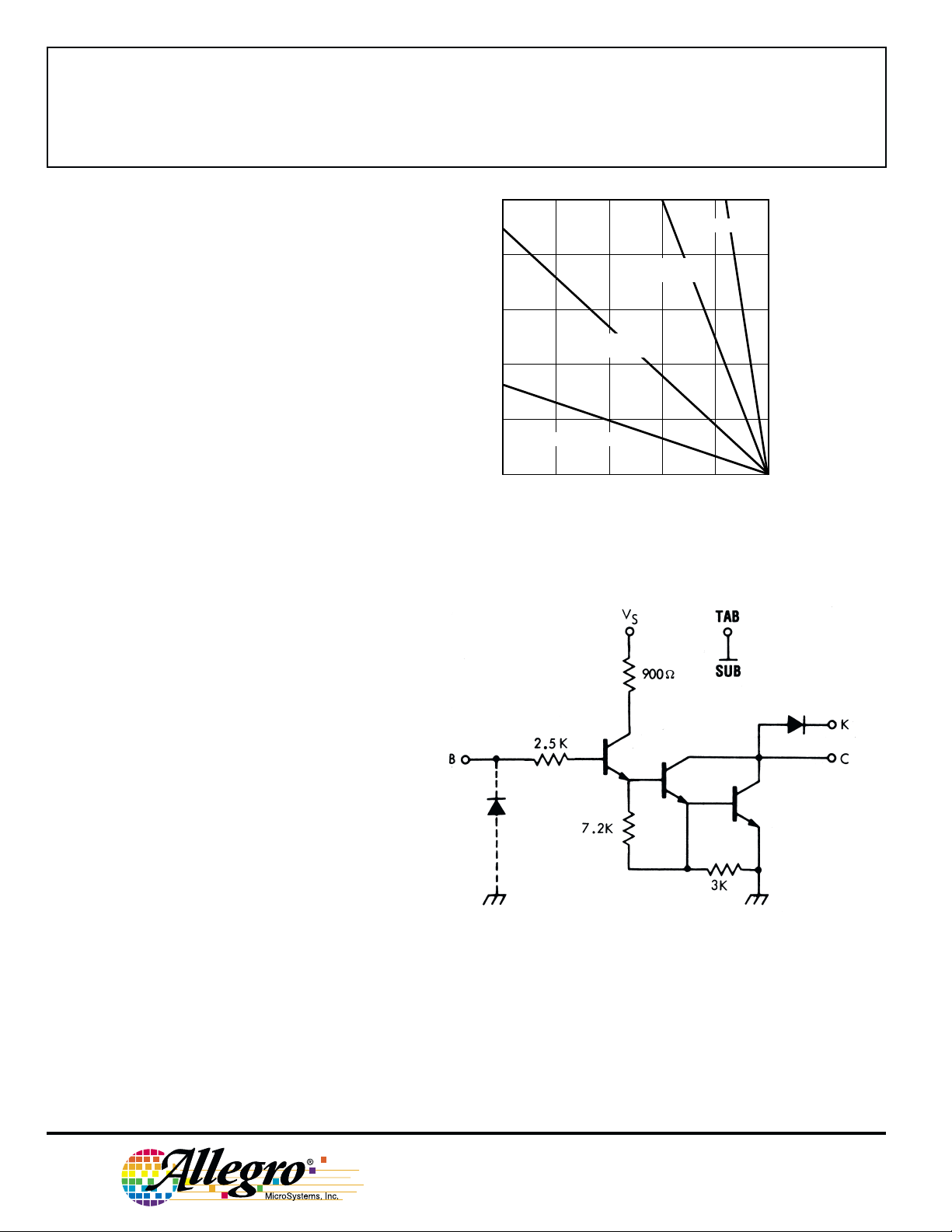
10
R = 2.0°C/W
θJT
8
6
12°C/W HEAT SINK
4
2
FREE AIR, R = 38°C/W
0
ALLOWABLE PACKAGE POWER DISSIPATION IN WATTS
25
50 75 100 125 150
TEMPERATURE IN °C
3.0°C/W HEAT SINK
R = 14°C/W
θJA
θJA
R = 5.0°C/W
θJA
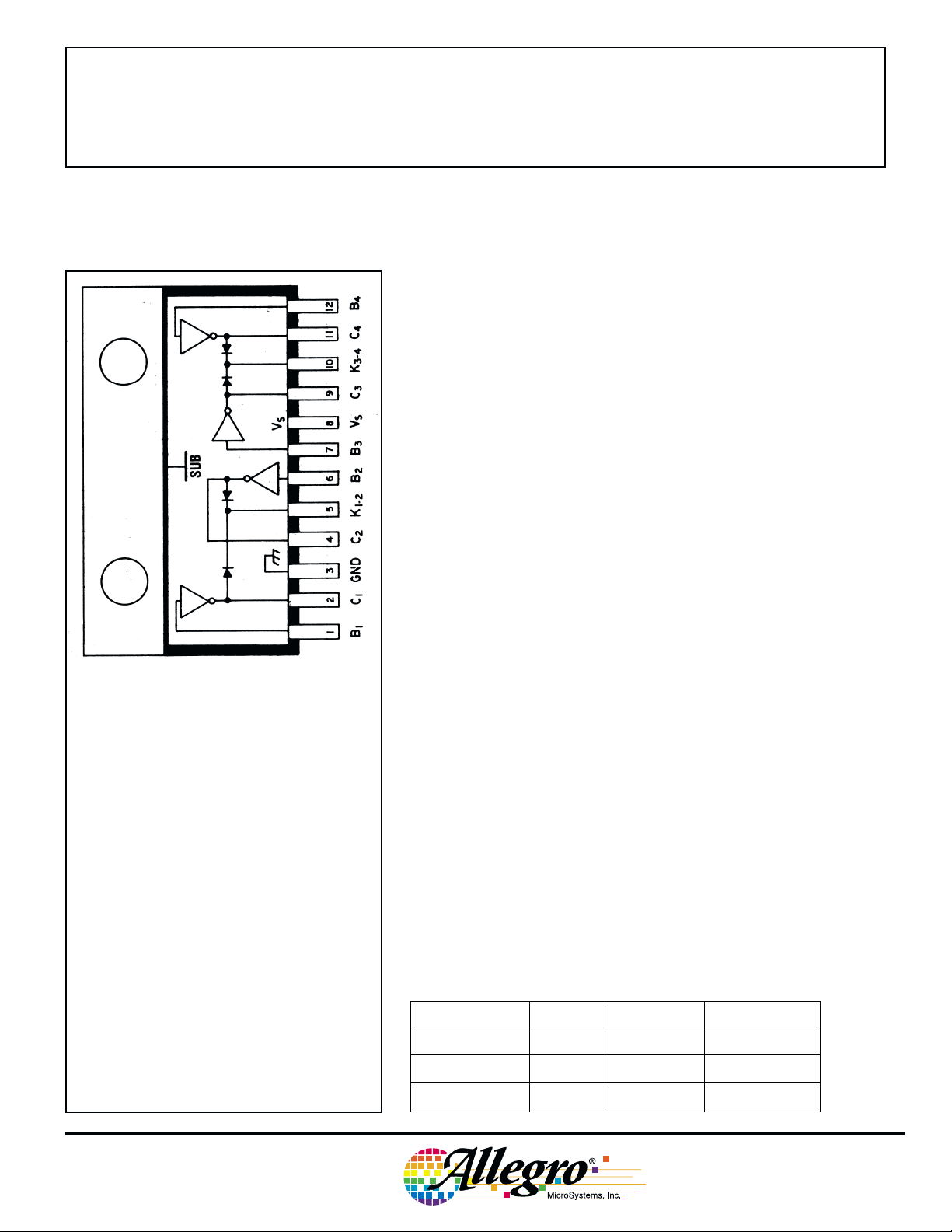
PARTIAL SCHEMATIC
One of 4 Drivers
Dwg. GP-012B
NOTE: Pin 3 must be connected to ground for proper operation.
115 Northeast Cutoff, Box 15036
Worcester, Massachusetts 01615-0036 (508) 853-5000
Copyright © 1983, 2000 Allegro MicroSystems, Inc.
Dwg. No. A-12,037
Page 3
2878
AND
QUAD HIGH-CURRENT
DARLINGTON SWITCHES
ELECTRICAL CHARACTERISTICS at VS = 5.0 V, TA = +25°C (unless otherwise noted).
2879
Test Applicable
Limits
Characteristic Symbol Fig. Devices Test Conditions Min. Max. Units
Output Leakage Current I
CEX
1 UDN2878W VCE = 50 V — 100 µA
V
= 50 V, TA = +70°C — 500 µA
CE
UDN2879W/W-2 V
= 80 V — 100 µA
CE
VCE = 80 V, TA = +70°C — 500 µA
Output Sustaining V
Voltage
CE(sus)
— UDN2878W lC = 4 A, L = 10 mH 35 — V
UDN2879W l
= 4 A, L = 10 mH 50 — V
C
UDN2879W-2 lC = 3 A, L = 10 mH 50 — V
Collector-Emitter V
Saturation Voltage
CE(SAT)
2All l
= 500 mA, VIN = 2.75 V — 1.1 V
C
l
= 1.0 A, VIN = 2.75 V — 1.3 V
C
lC = 2.0 A, VIN = 2.75 V — 1.5 V
l
= 3.0 A, VIN = 2.75 V — 1.9 V
C
Input Current I
Input Voltage V
IN
IN(ON)
UDN2878/79W l
3All V
4All V
= 4.0 A, VIN = 3.0 V — 2.4 V
C
= 2.75 V — 550 µA
IN
V
= 3.75 V — 1000 µA
IN
= 2.2 V, lC = 3.0 A — 2.75 V
CE
UDN2878/79W VCE = 2.2 V, lC = 4.0 A — 2.75 V
Supply Current per Driver I
Turn-On Delay t
Turn-Off Delay t
Clamp Diode I
S
PLH
PHL
R
7All l
— All 0.5 Ein to 0.5 E
— All 0.5 Ein to 0.5 E
5All V
Leakage Current
UDN2879W/W-2 VR = 80 V — 50 µA
Clamp Diode V
Forward Voltage
F
6All I
UDN2878/79W IF = 4.0 A — 3.0 V
Caution: High-current tests are pulse tests or require heat sinking.
= 500 mA, VIN = 2.75 V — 6.0 mA
C
out
, lC = 3.0 A — 1.5 µs
out
= 50 V — 50 µA
R
V
= 50 V, TA = +70°C — 100 µA
R
V
= 80 V, TA = +70°C — 100 µA
R
= 3.0 A — 2.5 V
F
— 1.0 µs
www.allegromicro.com
Page 4

2878
AND
2879
QUAD HIGH-CURRENT
DARLINGTON SWITCHES
TEST FIGURES
V
OPEN
IN
FIGURE 1
V
OPENVCE
µA
OPEN
V
V
CE
Dwg. No. A-9734A
OPEN
I
CEX
V
IN
V
V
CE
I
C
Dwg. No. A-10,350
FIGURE 2
V
R
I
IN
mA
V
IN
FIGURE 3
µA
I
R
OPEN
I
C
Dwg. No. A-9735A
OPEN
OPEN
Dwg. No. A-9732Dwg. No. A-9729A
Dwg. No. A-9736
OPEN
I
V
V
F
F
FIGURE 4
FIGURE 5 FIGURE 6
V
OPEN
S
I
S
mA
V
IN
I
C
Dwg. No. A-10,351
FIGURE 7
115 Northeast Cutoff, Box 15036
Worcester, Massachusetts 01615-0036 (508) 853-5000
Page 5

2878
QUAD HIGH-CURRENT
DARLINGTON SWITCHES
TYPICAL APPLICATIONS
INPUT WAVEFORMS STEPPER-MOTOR DRIVER
DIGIT DRIVER
FOR MULTIPLEXED INCANDESCENT LAMP DISPLAY
AND
Dwg. No. A-11,795
2879
Dwg. No. A-11,975
PRINT-HAMMER DRIVER
www.allegromicro.com
Dwg. No. A-11,976
Dwg. No. B-1512
Page 6

2878
AND
2879
QUAD HIGH-CURRENT
DARLINGTON SWITCHES
Dimensions in Inches
(controlling dimensions)
INDEX
AREA
0.065
0.035
0.020
1.260
1.240
0.775
0.765
0.245
0.225
0.180
0.155
MAX
0.055
0.045
ø
0.145
0.140
0.135
0.570
0.365
1
0.030
0.020
12
0.100
±0.010
0.540
0.290
0.023
0.018
MIN
0.100
0.080
0.070
NOTES: 1. Lead thickness is measured at seating plane or below.
2. Lead spacing tolerance is non-cumulative.
3. Exact body and lead configuration at vendor’s option within limits shown.
4. Lead gauge plane is 0.030” below seating plane.
5. Supplied in standard sticks/tubes of 15 devices.
115 Northeast Cutoff, Box 15036
Worcester, Massachusetts 01615-0036 (508) 853-5000
Dwg. MP-007 in
Page 7

Dimensions in Millimeters
(for reference only)
2878
AND
2879
QUAD HIGH-CURRENT
DARLINGTON SWITCHES
INDEX
AREA
1.65
0.89
0.51
1
32.00
31.49
19.69
19.45
0.76
0.51
12
6.22
5.71
3.56
9.27
2.54
±0.254
3.94
3.68
4.57
MAX
ø
14.48
13.71
7.36
MIN
0.59
0.45
1.40
1.14
3.43
2.54
2.03
1.77
NOTES: 1. Lead thickness is measured at seating plane or below.
2. Lead spacing tolerance is non-cumulative.
3. Exact body and lead configuration at vendor’s option within limits shown.
4. Lead gauge plane is 0.762 mm below seating plane.
5. Supplied in standard sticks/tubes of 15 devices.
The products described here are manufactured under one or more
U.S. patents or U.S. patents pending.
Allegro MicroSystems, Inc. reserves the right to make, from time to
time, such departures from the detail specifications as may be
required to permit improvements in the performance, reliability, or
manufacturability of its products. Before placing an order, the user is
cautioned to verify that the information being relied upon is current.
Allegro products are not authorized for use as critical components
in life-support devices or systems without express written approval.
The information included herein is believed to be accurate and
reliable. However, Allegro MicroSystems, Inc. assumes no responsibility for its use; nor for any infringement of patents or other rights of
third parties which may result from its use.
www.allegromicro.com
Dwg. MP-007 mm
Page 8

2878
AND
2879
QUAD HIGH-CURRENT
DARLINGTON SWITCHES
POWER SINK DRIVERS
IN ORDER OF 1) OUTPUT CURRENT, 2) OUTPUT VOLTAGE, 3) NUMBER OF DRIVERS
Output Ratings *
Serial Latched Diode Internal
mA V # Input Drivers Clamp Outputs Protection Part Number
75 17 8 X X –
17 16 X X –
100 20 8 – – – saturated – 2595
30 32 X X – – – 5833
40 32 X X – saturated – 5832
50 8 addressable decoder/driver DMOS – 6B259
50 8 – X – DMOS – 6B273
50 8 X X – DMOS – 6B595
250 50 8 addressable decoder/driver DMOS – 6259
50 8 – X – DMOS – 6273
50 8 X X – DMOS – 6595
135 7 – – X – – 7003
300 45 1 – Hall sensor/driver X – X 5140
50 8 – – X saturated – 2596
60 4 – – X saturated X 2557
350 50 4 – X X – – 5800
50 7 – – X – – 2003
50 7 – – X – – 2004
50 8 – – X – – 2803
50 8 – – X – – 2804
50 8 – X X – – 5801
50 8 X X – – – 5821
50 8 X X X – – 5841
50 8 addressable decoder/driver DMOS – 6A259
50 8 X X – DMOS – 6A595
80 8 X X – – – 5822
80 8 X X X – – 5842
95 7 – – X – – 2023
95 7 – – X – – 2024
95 8 – – X – – 2823
95 8 – – X – – 2824
450 30 28 dual 4- to 14-line decoder/driver – – 6817
600 60 4 – – – saturated X 2547
60 4 – – X saturated X 2549 and 2559
700 60 4 – – X saturated X 2543
750 50 8 – – X saturated – 2597
900 14 2 – Hall sensor/driver X saturated X 3625
26 2 – Hall sensor/driver X saturated X 3626
1000 46 4 stepper motor controller/driver MOS – 7024 and 7029
1200 46 4 microstepping controller/driver MOS – 7042
1250 50 4 stepper motor translator/driver – X 5804
50 4 – – X – – 2064 and 2068
1500 80 4 – – X – – 2065 and 2069
1800 50 4 – – X – – 2544
50 4 – – X – – 2540
3000 46 4 stepper motor controller/driver MOS – 7026
46 4 microstepping controller/driver MOS – 7044
4000 50 4 – – X – – 2878
80 4 – – X – – 2879
* Current is maximum specified test condition, voltage is maximum rating. See specification for sustaining voltage limits or
over-current protection voltage limits.
† Complete part number includes additional characters to indicate operating temperature range and package style.
Features
constant current
constant current
– 6275
– 6276
†
115 Northeast Cutoff, Box 15036
Worcester, Massachusetts 01615-0036 (508) 853-5000
 Loading...