

Page 1
Ultrasonic sensor UC500-30GM-2EP-IO-V15
Model Number
UC500-30GM-2EP-IO-V15
Single head system
Features
• IO-link interface for service and
process data
• Programmable via DTM with
PACTWARE
• 2 programmable switch outputs
• Selectable sound lobe width
• Synchronization options
• Temperature compensation
Diagrams
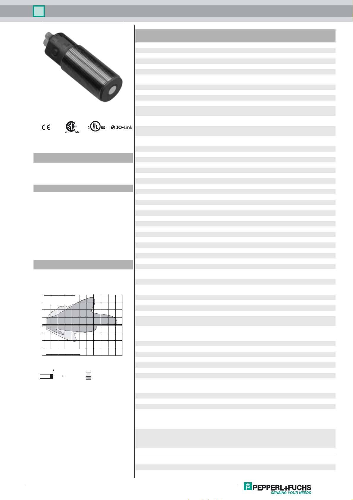
Characteristic response curve
Distance Y [mm]
200
flat surface
150
100 mm x 100 mm
100
50
0
-50
-100
-150
round bar, Ø 25 mm
-200
0 100 200 300 400 500 600 700 800 900 1000 1100
Y
X
Release date: 2017-10-24 12:02 Date of issue: 2017-10-27 191242_eng.xml
Refer to “General Notes Relating to Pepperl+Fuchs Product Information”.
Distance X [mm]
wide sound lobe
narrow sound lobe
Technical data
General specifications
Sensing range 30 ... 500 mm
Adjustment range 50 ... 500 mm
Dead band 0 ... 30 mm
Standard target plate 100 mm x 100 mm
Transducer frequency approx. 380 kHz
Response delay minimum : 25 ms
Memory
Non-volatile memory EEPROM
Write cycles 100000
Indicators/operating means
LED green solid: Power on
LED yellow 1 solid: Object in evaluation range
LED yellow 2 solid: Object in evaluation range
LED red solid red: Error
Electrical specifications
Operating voltage U
No-load supply current I
Power consumption P
Time delay before availability t
Interface
B
0
0
v
Interface type IO-Link
Protocol IO-Link V1.0
Transfer rate Acyclical: typical 240 Bit/s
Cycle time min. 13.2 ms
Mode COM 2 (38.4 kBaud)
Process data witdh 16 bit
SIO mode support yes
Input/Output
Input/output type 1 synchronization connection, bidirectional
0 Level 0 ... 1 V
1 Level 4 V ... U
Input impedance > 12 kΩ
Output rated operating current < 12 mA
Pulse length 0.5 ... 300 ms (level 1)
Pulse interval ≥ 14 ms (level 0)
Synchronization frequency
Common mode operation ≤ 70 Hz
Multiplex operation ≤ 90 Hz / n , n = number of sensors , n ≤ 10
Output
Output type 2 push-pull (4 in 1) outputs, short-circuit protected, reverse
Rated operating current I
Voltage drop U
Repeat accuracy ≤ 0.1 % of full-scale value
d
e
Switching frequency f ≤ 11 Hz
Range hysteresis H 1 % of the adjusted operating range (default settings),
Temperature influence ≤ 1.5 % from full-scale value (with temperature
Ambient conditions
Ambient temperature -25 ... 70 °C (-13 ... 158 °F)
Storage temperature -40 ... 85 °C (-40 ... 185 °F)
Mechanical specifications
Connection type Connector plug M12 x 1 , 5-pin
Degree of protection IP67
Material
Housing Stainless steel 1.4305 / AISI 303
Transducer epoxy resin/hollow glass sphere mixture; polyurethane foam
Mass 66 g
Factory settings
Output 1 near switch point: 50 mm
Output 2 near switch point: 100 mm
Beam width wide
Compliance with standards and
directives
Standard conformity
factory setting: 45 ms
flashing: Standby mode or IO link communication
flashing: Learning function, object detected
flashing: Learning function, object detected
red, flashing: program function, object not detected
10 ... 30 V DC , ripple 10 %
≤ 60 mA
SS
≤ 1 W
≤ 100 ms
B
(factory setting: n = 5 )
polarity protected
200 mA , short-circuit/overload protected
≤ 2.5 V
programmable
compensation)
≤ 0.2 %/K (without temperature compensation)
TPU
Polyamides
far switch point: 500 mm
output function: Window mode
output behavior: NO contact
far switch point: 250 mm
output function: Window mode
output behavior: NO contact
1
Page 2
Ultrasonic sensor UC500-30GM-2EP-IO-V15
Standards EN 60947-5-2:2007+A1:2012
Approvals and certificates
UL approval cULus Listed, General Purpose
CSA approval cCSAus Listed, General Purpose
CCC approval CCC approval / marking not required for products rated ≤36 V
IEC 60947-5-2:2007 + A1:2012
Dimensions
M30 x 1.5
2
5
56
36
LED
T1 T2
ø7
M12
81
93
Additional Information
Switching output operating modes
1. Switching point mode
NO contact
NC contact
2. Window mode
NO contact
NC contact
3. Hysteresis mode
NO contact
NC contact
4. Retroreflective sensor mode
NO contact
NC contact
Near
switching
point
Far
switching
point
Electrical Connection
Pinout
Wire colors in accordance with EN 60947-5-2
1 BN
2 WH
3 BU
4 BK
5 GY
1
5
4
2
3
2
L+
1
3
(brown)
(white)
(blue)
(black)
(gray)
Sync.
C/Q
Switch output 2
L-
5
4
Release date: 2017-10-24 12:02 Date of issue: 2017-10-27 191242_eng.xml
Refer to “General Notes Relating to Pepperl+Fuchs Product Information”.
2
Page 3

Ultrasonic sensor UC500-30GM-2EP-IO-V15
Accessories
IO-Link-Master02-USB
IO-Link master, supply via USB port or separate power supply, LED indicators, M12
plug for sensor connection
BF 30
Mounting flange, 30 mm
BF 30-F
Mounting flange with dead stop, 30 mm
BF 5-30
Universal mounting bracket for cylindrical sensors with a diameter of 5 ... 30 mm
V15-W-2M-PVC
Female cordset, M12, 5-pin, PVC cable
UVW90-M30
Ultrasonic -deflector
UVW90-K30
Ultrasonic -deflector
Description of Sensor Functions
Programming
The sensor is equipped with two outputs. Two switching points or trip values as well as the output mode, can be programmed for each output.
The shape of the sensor sound cone can also be programmed. These parameters can be configured using two different methods:
- Using the sensor push buttons
- Using the IO-link interface of the sensor. This method requires an IO-link master (e.g. IO-link master01 USB) and the associated software.
The download link is available on the product page for the sensor with the IO link at www.pepperl-fuchs.de
Configuration using the push buttons is described below. To configure the parameters using the sensor IO-link interface, please read the software
description. The processes for configuring the switching points and the sensor operating modes run completely independently and do not influence one another.
Note:
- The sensor can only be programmed during the first 5 minutes after switching on. This time is extended during the actual programming process. The option of programming the sensor is revoked if no programming activities take place for 5 minutes. After this, programming is no
longer possible until the sensor is switched off and on again.
- The programming activities can be canceled at any time without changing the sensor settings. To do so, press and hold the push button for
10 seconds.
Programming the switch points
Note:
Each push button is assigned to a physical output. Switching output 1 (C/Q) is programmed via push button T1. Switching output 2 is programmed
via push button T2. The status of switching output 1 is indicated by the yellow LED L1. The status of switching output 2 is indicated by the yellow
LED L2.
Programming the near switch point
1. Position the object at the site of the required near switch point.
2. Press and hold the push button for 2 seconds (yellow LED flashes).
3. Briefly press the push button (green LED flashes 3 times as confirmation). The sensor returns to normal mode.
Programming the distant switch point
1. Position the object at the site of the required distant switch point
2. Press and hold the push button for 2 seconds (yellow LED flashes)
3. Press and hold the push button for 2 seconds (green LED flashes 3 times as confirmation). The sensor returns to normal mode.
Programming the operating mode
The sensor features a 3-stage process for programming the sensor operating modes. You can program the following with this process:
1. Output function
2. Output behavior of the switching output
3. The beam width
These 3 stages of the process are programmed in succession. To switch from one programming function to the next, press and hold the push
button for 2 seconds.
Accessing the programming routine
The operating mode can be programmed separately for each of the two switching outputs. The switching output 1 (C/Q) operating mode is programmed via push button T1. The switching output 2 operating mode is programmed via push button T2.
To access the programming routine for the sensor operating mode, press the push button for 5 seconds.
Programming the output function of the switching output
The green LED is now flashing. The number of flashes indicates the output function currently programmed:
1x: Switching point mode
2x: Window mode
3x: Hysteresis mode
4x: Reflective mode
1. Briefly press the push button to navigate through the output functions in succession. Use this method to choose the required output function.
2. Press and hold the push button for 2 seconds to save the selection and switch to the programming routine for the output behavior.
Programming the output behavior for the switching output
The yellow LED is now flashing. The number of flashes indicates the output behavior currently programmed:
Release date: 2017-10-24 12:02 Date of issue: 2017-10-27 191242_eng.xml
Refer to “General Notes Relating to Pepperl+Fuchs Product Information”.
1x: NO contact
3
Page 4

Ultrasonic sensor UC500-30GM-2EP-IO-V15
2x: NC contact
1. Briefly press the push button to switch between the possible output behaviors in succession. Use this method to choose the output behavior.
2. Press and hold the push button for 2 seconds to save the selection and switch to the programming routine for the sound cone.
Programming the beam width
The red LED is now flashing. The number of flashes indicates the beam witdht currently programmed:
1x: narrow
2x: medium
3x: wide
1. Briefly press the push button to navigate through the different beam widths in succession. Use this method to choose the required beam
width.
2. Press and hold the push button for 2 seconds to return to normal operation mode.
Note
The last beam width programmed applies for both
Resetting the sensor to the factory settings
The sensor can be reset to the original factory settings.
1. Disconnect the sensor from the power supply
2. Press and hold one of the push buttons
3. Connect the power supply (yellow and red LEDs flash simultaneously for 5 seconds, followed by the yellow and green LEDs flashing simultaneously)
4. Release the push button
The sensor will now function with the original factory settings.
Factory settings
See technical data.
outputs in equal measure.
Indicators
The sensor has four LEDs for indicating the status and two buttons for setting parameters.
In normal mode
Error-free operation
Fault (e.g. compressed air)
When programming the switching
points or trip values
Object detected
No object detected
Confirmation, programming successful
Warning, programming invalid
When programming the operating
mode
Programming the output mode
Programming the output behavior
Programming the sound cone
LED,
green
On
Off
Off
Off
Flashes 3x
Off
Flashes
Off
Off
LED L1, yellow LED L2, yellow LED, red
The output status
retains the last
status
Flashes
Off
Off
Off
Off
Flashes
Off
L1
LED yellow LED yellow
LED
green/red
L2
T1 T2
The output status
retains the last
status
Flashes
Off
Off
Off
Off
Flashes
Off
L1
L2
Off
On
Off
Flashes
Off
Flashes 3x
Off
Off
Flashes
Synchronization
The sensor is fitted with a synchronization input that suppresses mutual interference from external ultrasonic signals. If this input is not connected,
the sensor operates with internally generated cycle pulses. The sensor can be synchronized by creating external rectangular pulses and by setting the appropriate parameters via the IO-link interface. Each falling pulse edge sends an individual ultrasonic pulse. If the signal at the synchronization input is low for >
1 second, the sensor reverts to the normal, unsynchronized operating mode. This also occurs if the synchronization input
is disconnected from external signals (see note below).
If a high signal is applied to the synchronization input for > 1 second, the sensor switches to standby. This is indicated by the green LED. In this
operating mode, the last recorded output statuses are retained. Please observe the software description in the event of external synchronization.
Note:
If the option of synchronizing is not used, the synchronization input must be connected to ground (L-) or the sensor must be operated with a V1connection cable (4-pin).
The option of synchronization is not available during the programming process. During synchronization, the sensor can switch to programming
via the IO-link interface. This interrupts the synchronization process and the sensor is no longer synchronized.
The following synchronization modes are available:
1. Multiple sensors (see Technical data for the maximum number) can be synchronized by connecting the synchronization inputs on the sensors. In this case, the sensors synchronize themselves in succession in multiplex mode. Only one sensor sends signals at any one time.
(See note below)
2. Multiple sensors (see Technical data for the maximum number) can be synchronized by connecting the synchronization inputs on the sensors. The sensor interface can be used to parameterize the sensors so that one functions as a master and the others function as slaves.
Release date: 2017-10-24 12:02 Date of issue: 2017-10-27 191242_eng.xml
Refer to “General Notes Relating to Pepperl+Fuchs Product Information”.
4
Page 5

Ultrasonic sensor UC500-30GM-2EP-IO-V15
(See interface description) In this case, the sensors in master/slave mode work simultaneously, i.e. in synchronization where the master sensor plays the role of an intelligent external impulse generator.
3. Multiple sensors can be controlled collectively by an external signal. In this case, the sensors are triggered in parallel and operate synchronously, i.e. at the same time. All sensors must be parameterized via the sensor interface so that they are set to external. See the software
description.
4. Several sensors are controlled with a time delay by an external signal. In this case, only one sensor is externally synchronized at any one
time (see note below). All sensors must be parameterized via the sensor interface so that they are set to external. See the software description.
5. A high signal (L+) or a low signal (L-) at the synchronization input switches the sensor to standby in the case of external parameterization.
Note:
The response time of the sensors increases in proportion to the number of sensors in the synchronization chain. In multiplex mode, the measuring
cycles of the individual sensors run in succession in a chronological sequence.
Note:
The synchronization connection of the sensors supplies an output current in the case of a low signal, and generates an input impedance in the
case of a high signal. Please note that the synchronizing device must have the following driver properties:
Driver current according to L+ >
Driver current according to L- >
n * high level signal/input impedance (n = number of sensors to be synchronized)
n * output current (n = number of sensors to be synchronized).
Release date: 2017-10-24 12:02 Date of issue: 2017-10-27 191242_eng.xml
Refer to “General Notes Relating to Pepperl+Fuchs Product Information”.
5
 Loading...