

Page 1
Ultrasonic sensor UC2000-L2-E4-V15
Technical data
General specifications
Sensing range 60 ... 2000 mm
Adjustment range 80 ... 2000 mm
Dead band 0 ... 60 mm
Standard target plate 100 mm x 100 mm
Transducer frequency approx. 175 kHz
Model Number
UC2000-L2-E4-V15
Single head system
Features
• Sensor head bidirectional and rotatable
• Function indicators visible from all
directions
• Quick mounting bracket
• Selectable sound lobe width
• Programmable
Diagrams
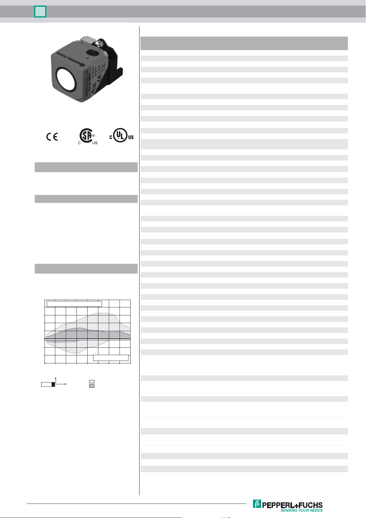
Characteristic response curve
Distance Y [mm]
1000
flat surface 100 mm x 100 mm
800
600
400
200
0
-200
-400
-600
0 500 1000 1500 2000 2500 3000 3500 4000
Y
X
round bar, Ø 25 mm
Distance X [mm]
wide sound lobe
narrow sound lobe
Response delay minimum : 60 ms
Indicators/operating means
LED green Operating display
LED yellow switching state
LED red error
Electrical specifications
Operating voltage U
No-load supply current I
Interface
B
0
Interface type Serial interface (programming adapter required)
Input/Output
Input/output type 1 synchronization connection, bidirectional
0 Level 0 ... 1 V
1 Level 4 V ... U
Input impedance > 12 kΩ
Output rated operating current < 12 mA
Pulse length 0.5 ... 300 ms (level 1)
Pulse interval ≥ 33 ms (level 0)
Synchronization frequency
Common mode operation ≤ 30 Hz
Multiplex operation ≤ 33 Hz / n , n = number of sensors , n ≤ 10
Input
Input type 1 program input
Level (switch point 1) 0 ... 1 V
Level (switch point 2) 4 V ... U
Input impedance > 10 kΩ
Pulse length 2 ... 10 s
Output
Output type 1 switching output E4, NPN, NO/NC, programmable
Rated operating current I
Voltage drop U
Repeat accuracy ≤ 0.1 % of full-scale value
d
e
Switching frequency f ≤ 5 Hz
Range hysteresis H programmable , preset to 1 mm
Temperature influence < 1.5 % of full-scale value
Ambient conditions
Ambient temperature -25 ... 70 °C (-13 ... 158 °F)
Storage temperature -40 ... 85 °C (-40 ... 185 °F)
Mechanical specifications
Connection type Connector M12 x 1 , 5-pin
Degree of protection IP67
Material
Housing PA-GF35
Transducer epoxy resin/hollow glass sphere mixture; polyurethane foam
Mass 115 g
Factory settings
Output near switch point: 80 mm
Beam width wide
Evaluation procedure averaging (MxN)
General information
Supplementary information Switch settings of the external programming adapter:
Compliance with standards and
directives
Standard conformity
Standards EN 60947-5-2:2007 + A1:2012
Ex works settings: 120 ms
10 ... 30 V DC , ripple 10 %
SS
≤ 50 mA
9600 BPS, no parity, 8 data bits, 1 stop bit
B
(factory setting: n = 5 )
B
200 mA , short-circuit/overload protected
≤ 2 V
far switch point: 2000 mm
output function: Window mode
output behavior: NO contact
M = 5
N = 2
"output load": pull-up
"output logic": inv
IEC 60947-5-2:2007 + A1:2012
Release date: 2016-02-15 08:50 Date of issue: 2016-02-15 277763_eng.xml
Refer to “General Notes Relating to Pepperl+Fuchs Product Information”.
Approvals and certificates
UL approval cULus Listed, General Purpose
CSA approval cCSAus Listed, General Purpose
CCC approval CCC approval / marking not required for products rated
≤36 V
1
Page 2
Ultrasonic sensor UC2000-L2-E4-V15
Dimensions
LED yeLED gnLED ye
40
3
LED gn
28
7
67
40
M12 x 1
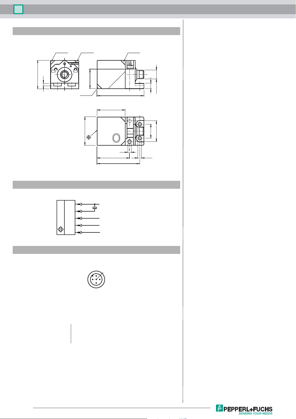
Electrical Connection
Pinout
40
T
out pwr
5.5
60
1
4
2
5
3
2
L+
Switch output
Program input
Synchronization
L-
1
5
4
20
30
ø 5.546
3
Wire colors in accordance with EN 60947-5-2
1 BN
2 WH
3 BU
4 BK
5 GY
Refer to “General Notes Relating to Pepperl+Fuchs Product Information”.
(brown)
(white)
(blue)
(black)
(gray)
Release date: 2016-02-15 08:50 Date of issue: 2016-02-15 277763_eng.xml
2
Page 3

Ultrasonic sensor UC2000-L2-E4-V15
Accessories
UC-PROG1-USB
Programming adapter
PACTware 4.X
FDT Framework
Ultraschall-Sensoren DTM
DTM devices for communication with cube style and UMC... sensors
V15-G-2M-PVC
Female cordset, M12, 5-pin, PVC cable
UB-PROG2
Programming unit
Microsoft .NET
Description of Sensor Functions
Programming procedure
The sensor features a single output with two programmable switch points. Programming the switch points and the operating mode can be done in three different ways:
- via the sensor’s Programming Button
- by applying the supply voltage 0 V or +U
- via the serial interface, which requires an external interface adapter
Procedures for programming via the sensor's Programming Button and the Program input are described below. For programming using the serial interface, please refer to the
software manual. Switch points and operating modes can be programmed independently without influencing each other
Note:
- Programming is enabled for 5 minutes after power-on. After 5 minutes without programming activity the programming feature will be locked.
- During any programming step it is possible to leave the programming routine without changing the sensor settings by pressing the Programming Button for 10 s.
to the Program input (only for programming the switch points)
B
Programming the Switch Points
Note:
If the red LED flashes during the programming procedure, it indicates uncertain target detection. In this case, please correct the target alignment until the yellow LED flashes.
The new settings will only be stored in the sensor’s memory if the yellow LED flashes.
Programming Switch Points using the Internal Programming Button
Programming the Near Switch Point
1. Place the target at the desired near switch point position
2. Press the Programming Button for 2 s (yellow LED flashes)
3. Press the Programming Button briefly (green LED flashes three times for confirmation). The sensor returns to normal operation.
Programming of the Far Switch Point
1. Place the target at the desired far switch point position
2. Press the Programming Button for 2 s (yellow LED flashes)
3. Press the Programming Button for 2 s (green LED flashes three times for confirmation). The sensor returns to normal operation.
Programming Switch Points by using the Program input wire
Notes:
- Before entering program mode the program input wire must be open circuit for at least 2s.
- If potential (0V or +U
input before this 10 s time period elapses.
- If the program input is not used, the wire should be connected to 0 V.
- If programming adapter UB-PROG2 is used for the programming procedure, button A1 is assigned to 0 V and button A2 is assigned to +U
cordset’s wire, which is connected to the Program input is not connected (open circuit).
Programming the Near Switch Point
1. Place the target at the desired near switch point position
2. Apply 0 V to the Program input for 2 s (yellow LED flashes, then green LED flashes three times for confirmation). Then sensor returns to normal operation.
Programming the Far Switch Point
1. Place the target at the desired far switch point position
2. Apply +U
to the Program input for 2 s (yellow LED flashes, then green LED flashes three times for confirmation). Then sensor returns to normal operation.
B
) is applied for >10 s the sensor resumes normal operation without changing settings. To ensure successful programming, disconnect the Program
B
. Please make sure, that the
B
Programming Modes of Operation
The sensor provides a three step routine to program the modes of operation. In this routine you can program:
1. Output function
2. Output behavior
3. Beam width
Programming the modes is carried out sequentially. To toggle from one mode to the next, press the Programming Button for 2 s.
Press the Programming Button for 5 s to enter the operating modes programming routine.
Programming the output function
1. The green LED flashes. The number of flashes indicates the current output function:
single flash: Switch point output function
double flash: Window output function
triple flash: Hysteresis output function.
2. Press the Programming Button briefly to toggle sequentially through these output functions and select the desired mode.
Release date: 2016-02-15 08:50 Date of issue: 2016-02-15 277763_eng.xml
Refer to “General Notes Relating to Pepperl+Fuchs Product Information”.
3
Page 4

Ultrasonic sensor UC2000-L2-E4-V15
3. Press the Programming Button for 2 s to save and enter the programming routine for output behavior
Programming the output behavior
1. The yellow LED flashes. The number of flashes indicates the current output behavior:
single flash: Normally Open (NO)
double flash: Normally Closed (NC).
2. Press the Programming Button briefly to toggle sequentially through these output behaviors and select the desired mode.
3. Press the Programming Button for 2 s to save and enter the programming routine for beam width.
Programming the beam width
1. The red LED flashes. The number of flashes indicates the current beam width setting:
single flash: narrow
double flash: medium
triple flash: wide.
2. Press the Programming Button briefly to toggle sequentially through these beam shapes.
3. Press the Programming Button for 2 s to save and exit the operating modes programming routine.
Reset Sensor to Factory Settings
The sensor has a feature to reset to factory settings
1. Disconnect the sensor from power supply
2. Press and hold the Programming Button
3. Connect Sensor to power supply (yellow and red LED flash simultaneously for 5 s then yellow and green LED flash simultaneously)
4. Release Programming Button
The sensor now operates with default factory settings.
Factory settings
See technical data.
Display
The sensor is provided with three LEDs to indicate various conditions.
#
During Normal operation
Proper operation
Interference (e.g. compressed air)
During Switch Point Programming
Object detected
No object detected
Confirmation after Programming
Programming failed warning
During Sensor Mode Programming
Programming the output function
Programming the output behaviour
Programming the beam width
Green LED Yellow LED Red LED
On
Off
Off
Off
Triple flashing
Off
Flashing
Off
Off
Switching state
remains in previous state
Flashing
Off
Off
Off
Off
Flashing
Off
Off
On
Off
Flashing
Off
Triple flashing
Off
Off
Flashing
Synchronization
This sensor features a synchronization input for suppressing ultrasonic mutual interference ("cross talk"). If this input is not connected, the sensor will operate freewheeling
using internally generated clock pulses. It can be synchronized by applying an external square wave or by means of appropriate programming via the serial interface. Each
falling edge of the synchronization pulse triggers transmission of a single ultrasonic pulse. If the synchronization signal remains low for ≥ 1 second, the sensor will revert to
normal operating mode. Normal operating mode can also be activated by opening the signal connection to the synchronization input.(See note below)
If the synchronization input goes to a high level for > 1 second, the sensor will switch to standby mode, indicated by the green LED. In this mode, the output(s) will remain in
the last valid output state. When using the external synchronization feature, please refer to the software description.
Note:
If the option for synchronization is not used, the synchronization input has to be connected to ground (0V) or the sensor has to be operated via a V1 cordset (4-pin).
The synchronization function cannot be activated during programming mode and vice versa.
The following synchronization modes are possible:
1. Several sensors (max. number see technical data) can be synchronized together by interconnecting their respective synchronization inputs. In this case, each sensor
alternately transmits ultrasonic pulses in a self multiplexing mode. No two sensors will transmit pulses at the same time. (See note below)
2. Several sensors (max. number see technical data) can be synchronized together by interconnecting their respective synchronization inputs. Due to programming via the
sensors interface one sensor acts as a master device, all the others as slave devices. (see description of the interface) In this master / slave mode the sensors are triggered
in parallel and are synchronized by a common synchronization pulse, provided by the master device.
3. Multiple sensors can be controlled by the same external synchronization signal. In this mode the sensors are triggered in parallel and are synchronized by a common
external synchronization pulse. All sensors must be parameterized for external synchronization by means of the sensor interface. See software description.
4. A separate synchronization pulse can be sent to each individual sensor. In this mode the sensors operate in external multiplex mode. (See note below). All sensors must
be parameterized for external synchronization by means of the sensor interface. See software description.
5. A high level (+U
Note:
Sensor response times will increase proportionally to the number of sensors that are in the synchronization string. This is a result of the multiplexing of the ultrasonic transmit
and receive signal and the resulting increase in the measurement cycle time.
Note:
The sensors syncronization input delivers an output current in case of low level and burdens with its input impedance in case of high level. Please pay attention that the synchronizing device needs to have that driver capability:
driver current against +U
driver current against 0V ≥ n * output current (n = number of sensors to be synchronized).
Release date: 2016-02-15 08:50 Date of issue: 2016-02-15 277763_eng.xml
Refer to “General Notes Relating to Pepperl+Fuchs Product Information”.
) or a low level (-UB)on the synchronization input switches the sensor to standby mode if it is parameterized for external synchronization.
B
≥ n * high-level/input impedance (n = number of sensors to be synchronized)
B
4
Page 5

Ultrasonic sensor UC2000-L2-E4-V15
Release date: 2016-02-15 08:50 Date of issue: 2016-02-15 277763_eng.xml
Refer to “General Notes Relating to Pepperl+Fuchs Product Information”.
5
 Loading...