

Page 1
Ultrasonic sensor UC2000-30GM70-2E2R2-K-V15
Technical data
General specifications
Sensing range 100 ... 2000 mm
Adjustment range 150 ... 2000 mm
Dead band 0 ... 100 mm
Standard target plate 100 mm x 100 mm
Transducer frequency approx. 200 kHz
Response delay ≤ 100 ms
Nominal ratings
Temperature drift ≤ ± 1.5 % of full-scale value
Model Number
UC2000-30GM70-2E2R2-K-V15
Ultrasonic diffuse sensor with separate
transducer
Features
•2 switch outputs
• Synchronization options
• Temperature compensation
• Can be parameterized via the ULTRA-PROG-IR software and interface (accessories)
Diagrams
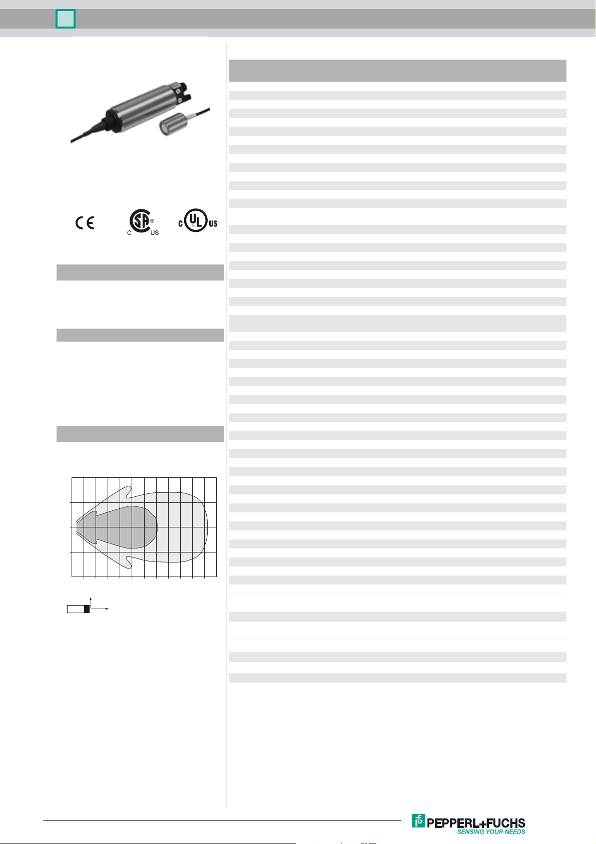
Characteristic response curve
Distance Y [mm]
500
250
0
-250
-500
0 250 500 750 1000 1250 1500 1750 2000 2250 2500 2750 3000
Y
Curve 1: flat surface 100 mm x 100 mm
Curve 2: round bar, Ø 25 mm
2
X
1
Distance X [mm]
Time delay before availability t
Limit data
Permissible cable length max. 300 m
Indicators/operating means
LED yellow solid Switching state switch output 1
LED green/yellow yellow: switching state switch output 2
Potentiometer Switching output 1 and Switching output 2 adjustable
Electrical specifications
Rated operating voltage U
Operating voltage U
Ripple ≤ 10 %
No-load supply current I
Interface
Interface type Infrared
Mode point-to-point connection
Input/Output
Input/output type 1 synchronization connection, bidirectional ( Factory setting:
0 Level ≤ 3 V
1 Level ≥ 15 V
Input impedance typ. 900 Ω
Number of sensors max. 10
Switching output
Output type 2 switch outputs PNP, NO ( NC contact programmable )
Default setting 150 ... 2000 mm ( adjustable via potentiometer )
Repeat accuracy R ± 3 mm
Operating current I
Switching frequency ≤ 4 Hz
Switching hysteresis 20 mm ( programmable )
Voltage drop ≤ 3 V
Off-state current ≤ 10 µA
Ambient conditions
Ambient temperature -25 ... 70 °C (-13 ... 158 °F)
Storage temperature -40 ... 85 °C (-40 ... 185 °F)
Shock resistance 30 g , 11 ms period
Vibration resistance 10 ... 55 Hz , Amplitude ± 1 mm
Mechanical specifications
Connection type Connector M12 x 1 , 5-pin
Degree of protection IP65
Material
Housing brass, nickel-plated
Cable PVC
Transducer epoxy resin/hollow glass sphere mixture; polyurethane foam
Installation position any position
Mass 190 g
Construction type Cylindrical
Cable length 165 cm
Compliance with standards and
directives
Standard conformity
Standards EN 60947-5-2:2007 + A1:2012
B
L
v
e
0
≤ 125 ms
green: Teach-In
24 V DC
12 ... 30 V DC (including ripple)
≤ 50 mA
synchronized mode ) / Teach-In input
Per 150 mA , short-circuit/overload protected
IEC 60947-5-2:2007 + A1:2012
Release date: 2016-02-16 08:30 Date of issue: 2016-02-16 238384_eng.xml
Refer to “General Notes Relating to Pepperl+Fuchs Product Information”.
Approvals and certificates
UL approval cULus Listed, General Purpose
CSA approval cCSAus Listed, General Purpose
CCC approval CCC approval / marking not required for products rated
≤36 V
1
Page 2
Ultrasonic sensor UC2000-30GM70-2E2R2-K-V15
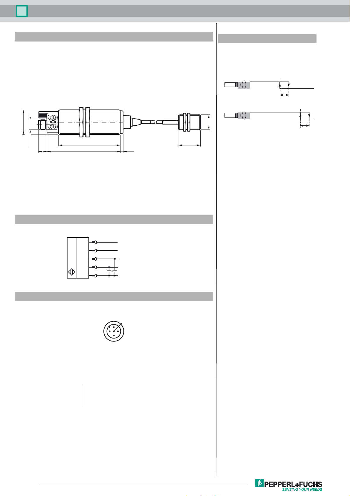
Dimensions
M30 x 1.5
M12 x 1
10.5 88.5 3.3
74.4
26.7
Additional Information
Switching outputs operating mode
Switching output mode
Output 1
Blind zone
Output 2
Blind zone
M18 x 1
switching point
h
switching point
h
Electrical Connection
Pinout
Wire colors in accordance with EN 60947-5-2
1 BN
2 WH
3 BU
4 BK
5 GY
1
2
4
5
3
2
L+
XI
Switch output 1
Switch output 2
1
3
(brown)
(white)
(blue)
(black)
(gray)
L-
5
4
Release date: 2016-02-16 08:30 Date of issue: 2016-02-16 238384_eng.xml
Refer to “General Notes Relating to Pepperl+Fuchs Product Information”.
2
Page 3

Ultrasonic sensor UC2000-30GM70-2E2R2-K-V15
Accessories
BF 30
Mounting flange, 30 mm
BF 5-30
Universal mounting bracket for cylindrical sensors with a diameter of 5 ... 30 mm
V15-G-2M-PUR
Female cordset, M12, 5-pin, PUR cable
UC-18/30GM-IR
Interface cable
ULTRA-PROG-IR
Configuration software for ultrasonic sensors
BF 18
Mounting flange, 18 mm
Description of Sensor Functions
Displays and Controls
The sensor has two potentiometers and two display LEDs.
LED 1 (yellow)
LED 2 (yellow)
LED 2 (green)
Potentiometer 1 Setting a switching point
Potentiometer 2 Setting a switching point
On/off:
Switching state of switching output 1
Flashing:
points (switching point 2 < switching point 1).
This state only occurs in window function
operating mode (2 switching points).
On/off:
Flashing:
points (switching point 2 < switching point 1).
This state only occurs in window function
operating mode (2 switching points).
approx. 500 ms on:
Off:
(Default setting: Setting the
switching point of switching output 1)
(Default setting: Setting the
switching point of switching output 2)
Error when setting the switching
Switching state of switching output 2
Error when setting the switching
Range limit taught in
Normal mode
potentiometer 2
LED 1
yellow
potentiometer 1 temperature
LED 2
yellow / green
connector
sensor
Setting the Sensor Using the Potentiometers
The sensor is equipped with two potentiometers. These potentiometers are assigned to the two switching outputs by default. The switching outputs operate in switching point mode by default. Potentiometer P1 is used to set the switching point on switching output 1. Potentiometer P2 is
used to set the switching point on switching output 2.
Note:
The function of the potentiometer can be altered using the ULTRA-PROG-IR software. As soon as a configuration has been changed, the potentiometer function selected using ULTRA-PROG-IR is activated.
Parameterization via ULTRA-PROG-IR
In order to be able to set the sensor parameters and adjust the sensor to the respective application, the sensor is able to communicate with a PC
via the integrated infrared interface. The UC-18/30GM-IR interface cable is required to allow communication via this method. This cable is connected to an unused USB port on the PC.
UC-18/30GM-IR
The ULTRA-PROG-IR parameterization software is also required for setting the sensor parameters. The ULTRA-PROG-IR software can be
downloaded for free from the website. The software allows all open parameters to be set, including:
- All trip points and switchi
- Output modes and behaviors
-Delay times
- Settings and setting ranges of the potentiometer
- Settings for teach-in and synchronization
- Definition of blind zones
- Sensor modes and measurement methods
- Filtering measurement values
The following service functions are also available:
- Observing and recording measurement values
- Diagnosing interference reflections
Release date: 2016-02-16 08:30 Date of issue: 2016-02-16 238384_eng.xml
Refer to “General Notes Relating to Pepperl+Fuchs Product Information”.
Sensor
3
Page 4

Ultrasonic sensor UC2000-30GM70-2E2R2-K-V15
Teach-in
The sensor is equipped with a function input (XI). In order to teach in a limit value, this sensor must be parameterized as the Teach-in input using
the ULTRA-PROG-IR parameterization software. This parameterization software allows you to specify what limit value is taught in.
Note:
The Teach-in function is not activated when the sensor is delivered.
Description of the Teach-in process:
1. Position an object at the required distance.
2. Connect the Teach-in input to L-.
The green LED lights up briefly after approx. 3 seconds. This indicates that the required distance has been successfully saved.
3. Disconnect the Teach-in input from L-.
Note:
If the Teach-in input remains connected to L-, the Teach-in process is repeated every 3 seconds.
Synchronization
The sensor features a function input (XI). Using the ULTRA-PROG-IR parameterization software, this function input can be configured as a synchronization input to suppress mutual interference from external ultrasonic signals. This is illustrated in the following description.
If the synchronization input is not connected, the sensor operates with internally generated cycle pulses.
External synchronization
The sensor can be synchronized by applying external rectangular pulses. The pulse duration must be ≥ 100 µs. Each rising pulse edge sends an
individual ultrasonic pulse. If the signal at the synchronization input is high, the sensor reverts to the normal, unsynchronized operating mode.
If a low signal is applied to the synchronization input, the sensor switches to standby. In this operating mode, the last recorded output statuses
are retained.
Internal synchronization
Common mode operation
Up to ten sensors can be synchronized with each other. To do this, the synchronization inputs of the individual sensors are connected to each
other. When configured in this state, all of the sensors send the ultrasonic signals together at the same time. The cycle rate corresponds to the
cycle rate of the sensor with the lowest rate.
Multiplex mode
Up to ten sensors can work in multiplex mode; i.e. the sensors send their ultrasonic signals in succession. This prevents the sensor signals interfering with each other. In multiplex mode, the synchronization inputs of all sensors are connected to each other. An address must also be assigned to each sensor using the ULTRA-PROG-IR parameterization software, and the number of sensors to be synchronized must be determined.
To start multiplex mode, all sensors are commissioned together by switching on the power supply.
Low Temperature Operation
If the sensor is installed at places, where the environment temperature can fall below 0 °C, for the sensor
head (4) fixation the included silicon rings (2) have to be used. Therefore a fixation hole Ø20
quired. The silicon rings (2) have to be placed between the fixation nuts (1) and the mounting base (3). Take
care that the silicon ring’s centering ring lays into the fixation hole.
+0.5
mm is re-
1 2 2
4
3
Release date: 2016-02-16 08:30 Date of issue: 2016-02-16 238384_eng.xml
Refer to “General Notes Relating to Pepperl+Fuchs Product Information”.
4
 Loading...