

Page 1
Ultrasonic direct detection sensor UB400-F77-E2-V31
Technical data
General specifications
Sensing range 25 ... 400 mm
Adjustment range 40 ... 400 mm
Dead band 0 ... 25 mm
Standard target plate 20 mm x 20 mm
Transducer frequency approx. 300 kHz
Nominal ratings
Model Number
UB400-F77-E2-V31
Ultrasonic direct detection sensor
Features
• Miniature design
• Program input
• Degree of protection IP67
• Switching status indicator, yellow
LED
Diagrams
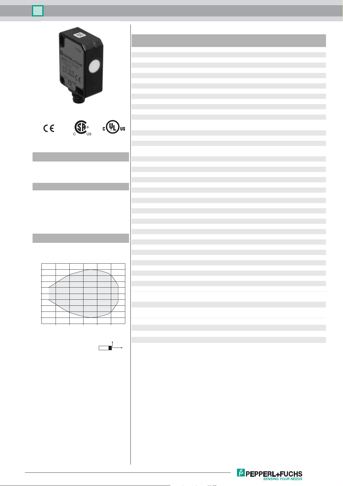
Characteristic response curve
Distance Y [mm]
50
40
30
20
10
0
-10
-20
-30
-40
-50
0 100 200 300 400 500 600
Distance X [mm]
Y
Time delay before availability t
Limit data
Permissible cable length max. 300 m
Indicators/operating means
LED yellow switching state and flashing: Teach-In
Electrical specifications
Rated operating voltage U
Operating voltage U
No-load supply current I
Input
Input type 1 program input
Level low level : 0 ... 0.7 V (Teach-In active)
Input impedance 16 kΩ
Pulse length ≥ 3 s
Output
Output type 1 switch output PNP, NO
Rated operating current I
Voltage drop U
Switch-on delay t
Repeat accuracy ± 1 mm
Switching frequency f 5 Hz
Range hysteresis H typ. 4 mm
Off-state current I
Temperature influence + 0.17 %/K
Ambient conditions
Ambient temperature -25 ... 70 °C (-13 ... 158 °F)
Storage temperature -40 ... 85 °C (-40 ... 185 °F)
Shock resistance 30 g , 11 ms period
Vibration resistance 10 ... 55 Hz , Amplitude ± 1 mm
Mechanical specifications
Connection type M8 x 1 connector , 4-pin
Degree of protection IP67
Material
Housing Polycarbonate
Transducer epoxy resin/hollow glass sphere mixture; polyurethane foam
Installation position any position
Mass 10 g
Tightening torque, fastening screws max. 0.2 Nm
Compliance with standards and
directives
Standard conformity
Standards EN 60947-5-2:2007 + A1:2012
Approvals and certificates
UL approval cULus Listed, General Purpose
CSA approval cCSAus Listed, General Purpose
CCC approval CCC approval / marking not required for products rated
X
B
d
on
r
v
e
0
e
≤ 150 ms
24 V DC
20 ... 30 V DC , ripple 10 %SS ; 12 ... 20 V DC sensitivity
reduced to 90 %
≤ 20 mA
high level : U
200 mA , short-circuit/overload protected
≤ 2 V
≤ 75 ms
≤ 0.01 mA
IEC 60947-5-2:2007 + A1:2012
≤36 V
or open input (Teach-In inactive)
B
Release date: 2016-02-12 15:20 Date of issue: 2016-02-12 233240_eng.xml
Refer to “General Notes Relating to Pepperl+Fuchs Product Information”.
1
Page 2
Ultrasonic direct detection sensor UB400-F77-E2-V31
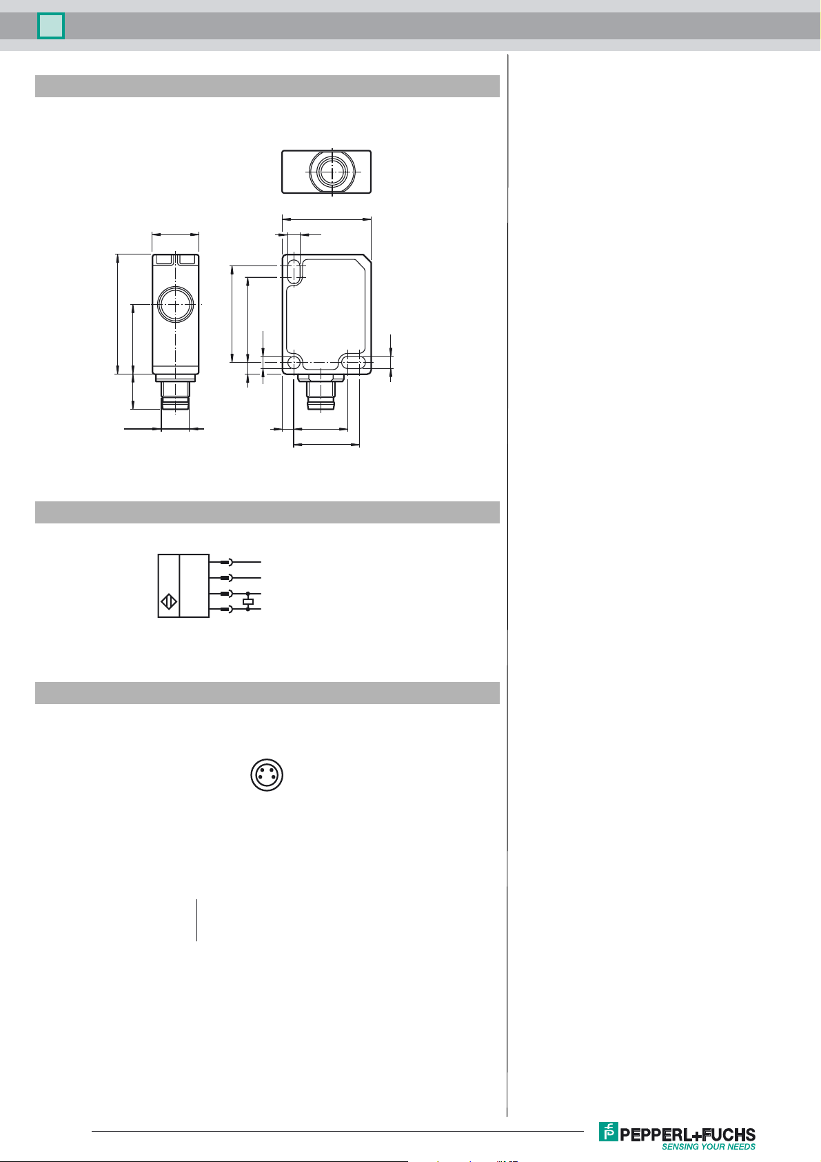
Dimensions
23
12
3.2
31
189
M8 x 1
Electrical Connection
Pinout
1
2
4
3
25
ø3.2
322
+U
ET (Teaching input)
Switching output
-U
3.2
3 14
17
B
B
24
13
Wire colors in accordance with EN 60947-5-2
1 BN
2 WH
3 BU
4 BK
Refer to “General Notes Relating to Pepperl+Fuchs Product Information”.
(brown)
(white)
(blue)
(black)
Release date: 2016-02-12 15:20 Date of issue: 2016-02-12 233240_eng.xml
2
Page 3

Ultrasonic direct detection sensor UB400-F77-E2-V31
Accessories
UB-PROG4-V31
Programming unit for ultrasonic sensors with Teach-in input at pin 2
OMH-ML7-01
Mounting aid for ML7 and ML8 series, Mounting bracket
V31-GM-2M-PVC
Female cordset, M8, 4-pin, PVC cable
V31-WM-2M-PVC
Female cordset, M8, 4-pin, PVC cable
Description of Sensor Function
The ultrasonic sensor transmits ultrasonic packets in quick succession and responds to their reflection off the detected object. The sensor has
a switch output. The switching point is progammable (Teach-In). Objects beyond the taught-in switching point are not detected (background
suppression).
Teach-In of Switching Point SP
To teach in a switching point, proceed as follows:
1. Connect the sensor and turn on the operating voltage.
2. Place the object to be detected at the required distance.
3. Connect the teach-in input (ET) to -U
The LED will start flashing after 3 seconds to indicate that the sensor is ready to start the teach-in process
4. Disconnect the teach-in input (ET) with -U
(*) If no object is detected within the sensing range of the sensor, the sensor will start flashing at a faster rate. The switching point remains
unchanged.
. This can be done usingthepushbutton or the controller.
B
. The switching point SP has now been taught in
B
(*)
(*)
.
.
Switching characteristics and display LED
unusable
area
" -U
" +U
" Undefined
" = Object position
Sensing range Output LED
Adjustment range
B
B
Off
On
Mounting instruction
If the sensor is operated at temperatures below 0 °C, use the supplied distance plate. Only use the two rearmost mounting holes (located opposite
to the transducer) for mounting the sensor.
Safety Note
The use of this device in applications, where the safety of persons depends from the devices function, is not allowed!
Release date: 2016-02-12 15:20 Date of issue: 2016-02-12 233240_eng.xml
Refer to “General Notes Relating to Pepperl+Fuchs Product Information”.
3
 Loading...