

Page 1
N
Datenblatt / Data sheet
Netz-Thyristor-Modul
Phase Control Thyristor
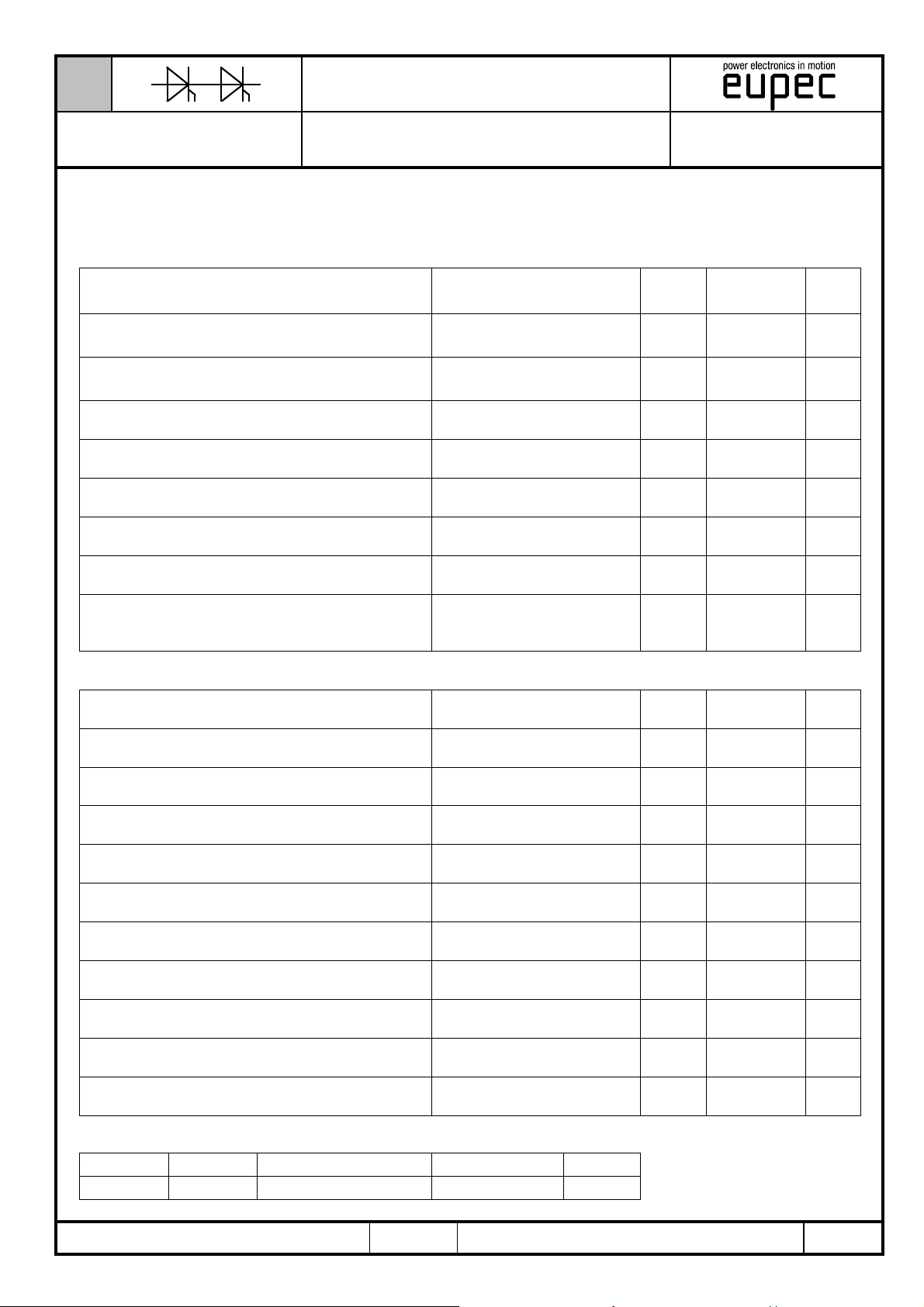
Kenndaten
Elektrische Eigenschaften / Electrical properties
Elektrische Eigenschaften
Höchstzulässige Werte / Maximum rated values
Periodische Vorwärts- und Rückwärts-Spitzensperrspannung
repetitive peak forward off-state and reverse voltages
Vorwärts-Stoßspitzensperrspannung
non-repetitive peak forward off-state voltage
Rückwärts-Stoßspitzensperrspannung
non-repetitive peak reverse voltage
Durchlaßstrom-Grenzeffektivwert
maximum RMS on-state current
Dauergrenzstrom
average on-state current
Stoßstrom-Grenzwert
surge current
Grenzlastintegral
I²t-value
Kritische Stromsteilheit
critical rate of rise of on-state current
Kritische Spannungssteilheit
critical rate of rise of off-state voltage
Module
TZ740N
T
= -40°C... T
vj
Tvj = -40°C... T
Tvj = +25°C... T
TC = 85°C
T
= 69°C
C
Tvj = 25 °C, tP = 10 ms
T
= T
vj
Tvj = 25 °C, tP = 10 ms
T
= T
vj
DIN IEC 747-6
f = 50 Hz, i
Tvj = T
6.Kennbuchstabe / 6
vj max
vj max
vj max
, tP = 10 ms
vj max
, tP = 10 ms
vj max
= 1 A, diG/dt = 1 A/µs
GM
, vD = 0,67 V
vj max
TZ740N
DRM
th
letter F
V
DRM,VRRM
V
DSM
V
RSM
I
TRMSM
I
TAVM
I
TSM
I²t
/dt)
(di
T
/dt)
(dv
D
1800 2000
1800 2000
1900 2100
cr
cr
2200VV
2200VV
2300VV
1500 A
740
955AA
30.000
26.500AA
4.500.000
3.500.000
200 A/µs
1000 V/µs
A²s
A²s
Charakteristische Werte / Characteristic values
Durchlaßspannung
on-state voltage
Schleusenspannung
threshold voltage
Ersatzwiderstand
slope resistance
Zündstrom
gate trigger current
Zündspannung
gate trigger voltage
Nicht zündender Steuerstrom
gate non-trigger current
Nicht zündende Steuerspannung
gate non-trigger voltage
Haltestrom
holding current
Einraststrom
latching current
Vorwärts- und Rückwärts-Sperrstrom
forward off-state and reverse current
Zündverzug
gate controlled delay time
Tvj = T
Tvj = T
Tvj = T
, iT = 3000 A v
vj max
vj max
vj max
Tvj = 25°C, vD = 6 V I
Tvj = 25°C, vD = 6 V V
Tvj = T
T
vj
Tvj = T
= T
, vD = 6 V
vj max
, vD = 0,5 V
vj max
, vD = 0,5 V
vj max
DRM
DRM
Tvj = 25°C, vD = 6 V, RA = 5 Ω I
Tvj = 25°C, vD = 6 V, RGK ≥ 10 Ω
i
= 1 A, diG/dt = 1 A/µs, tg = 20 µs
GM
Tvj = T
vj max
vD = V
DRM
, vR = V
RRM
DIN IEC 747-6
T
= 25 °C,iGM = 1 A, diG/dt = 1 A/µs
vj
V
r
T
GT
I
GD
V
H
I
L
iD, i
t
gd
T
(TO)
GT
GD
max.
1,65 V
0,9 V
0,21 mΩ
max.
max.
max.
max.
250 mA
2,2 V
105mA
mA
max. 0,25 V
max. 500 mA
max. 2500 mA
R
max. 150 mA
max. 4 µs
prepared by:
C.Drilling date of publication: 14.03.03
approved by: J. Novotny
BIP AC / 01-10-01, C. Drilling
A 22/00
revision: 1
Seite/page
1/12
Page 2
N
Datenblatt / Data sheet
Netz-Thyristor-Modul
Phase Control Thyristor
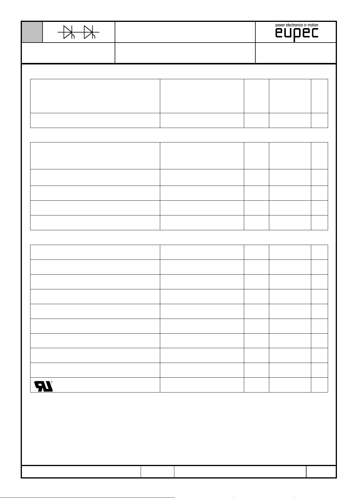
Elektrische Eigenschaften / Electrical properties
Charakteristische Werte / Characteristic values
Freiwerdezeit
circuit commutated turn-off time
Isolations-Prüfspannung
insulation test voltage
Thermische Eigenschaften / Thermal properties
Thermische Eigenschaften
Innerer Wärmewiderstand
thermal resistance, junction to case
Übergangs-Wärmewiderstand
thermal resistance, case to heatsink
Höchstzulässige Sperrschichttemperatur
maximum junction temperature
Betriebstemperatur
operating temperature
Lagertemperatur
storage temperature
Module
TZ740N
T
= T
vj max
, iTM = I
TAVM
DRM
th
letter O
vj
vRM = 100 V, vDM = 0,67 V
dvD/dt = 20 V/µs, -diT/dt = 10 A/µs
5.Kennbuchstabe / 5
RMS, f = 50 Hz, t = 1 min
RMS, f = 50 Hz, t = 1 sec
pro Modul / per Module, Θ = 180° sin
pro Modul / per Module, DC
pro Modul / per Module
t
V
R
R
T
T
T
q
thJC
thCH
vj max
c op
stg
ISOL
typ. 350 µs
3,0
3,6
max.
0,0420
max.
0,0405
max.
0,01
125
-40...+125 °C
-40...+130 °C
kV
kV
°C/W
°C/W
°C/W
°C
Mechanische Eigenschaften / Mechanical properties
Mechanische Eigenschaften
Gehäuse, siehe Anlage
case, see annex
Si-Element mit Druckkontakt
Si-pellet with pressure contact
Innere Isolation
internal insulation
Anzugsdrehmoment für mechanische Anschlüsse
mounting torque
Anzugsdrehmoment für elektrische Anschlüsse
terminal connection torque
Steueranschlüsse
control terminals
Gewicht
weight
Kriechstrecke
creepage distance
Schwingfestigkeit
vibration resistance
Seite 3
page 3
AlN
Toleranz / Tolerance ± 15% M1 6 Nm
Toleranz / Tolerance ± 10% M2 18 Nm
DIN 46 244 A 2,8 x 0,8
G typ. 2750 g
36 mm
f = 50 Hz 50 m/s²
file-No. E 83336
Mit diesem Datenblatt werden Halbleiterbauelemente spezifiziert, jedoch keine Eigenschaften zugesichert. Es gilt in
Verbindung mit den zugehörigen technischen Erläuterungen.
This data sheet specifies semiconductor devices, but promises no characteristics. It is valid in combination with the belonging
technical notes.
BIP AC / 01-10-01, C. Drilling
A 22/00
Seite/page
2/12
Page 3
N
Datenblatt / Data sheet
Netz-Thyristor-Modul
Phase Control Thyristor
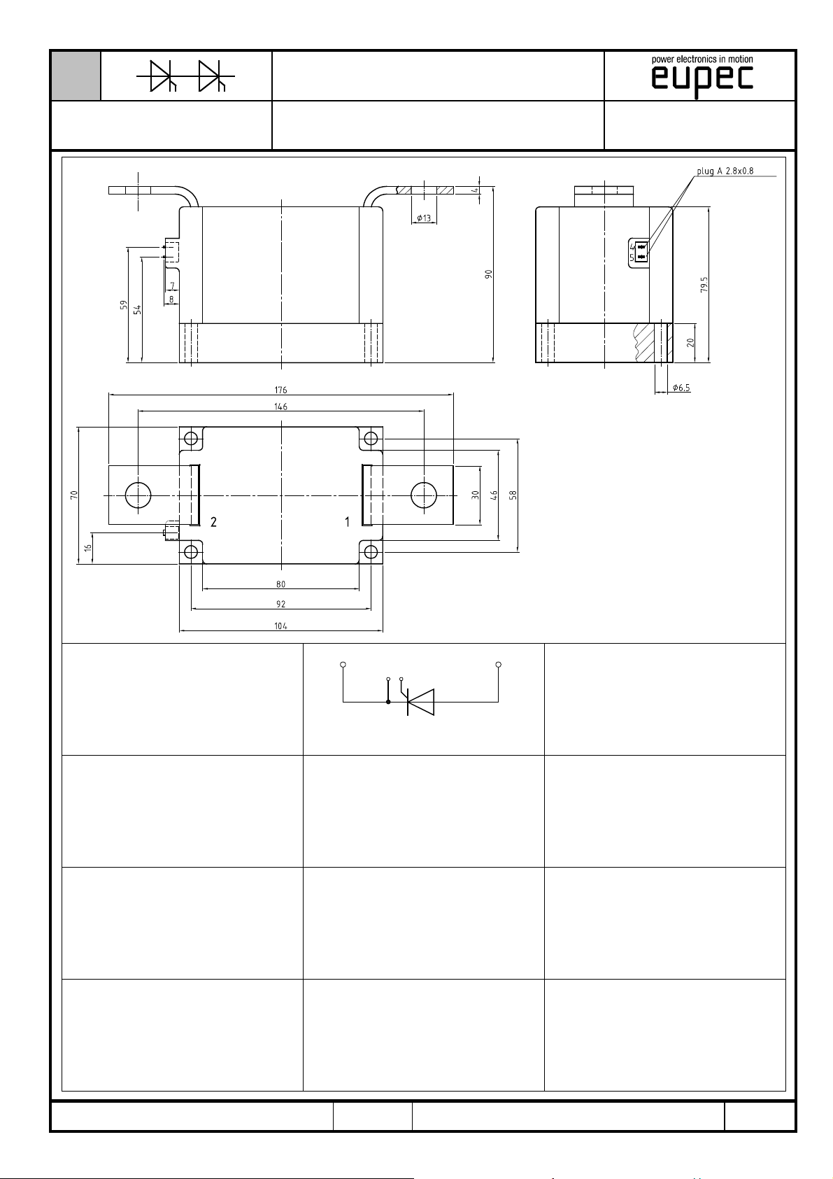
Maßbild
Maßbild
Maßbild
Module
TZ740N
21
45
TZ
BIP AC / 01-10-01, C. Drilling
A 22/00
Seite/page
3/12
Page 4
N
S
=
Datenblatt / Data sheet
Netz-Thyristor-Modul
Phase Control Thyristor
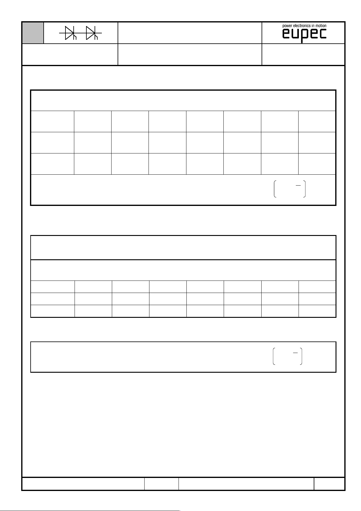
R,T – Werte
Di
R,T-Werte
Pos. n1234567
R
[°C/W] 0,0011 0,00267 0,00866 0,02313 0,00507
thn
τn [s] 0,01 0,0188 0,30347 4,994 9,98
Analytische Elemente des transienten Wärmewiderstandes Z
Analytische Funktion / Analytical function:
Module
Analytical elements of transient thermal impedance Z
TZ740N
=
thJC
n
max
S
n=1
für DC
thJC
for DC
thnthJC
– t
t
n
- e1RZ
Verstärkte Kühlung / Forced cooling
1 Module pro Kühlkörper / 1 modules per heatsink
Kühlkörper / Heatsink type: KW70 (4l/min.)
Analytische Elemente des transienten Wärmewiderstandes Z
Analytical elements of transient thermal impedance Z
Pos. n1234567
R
[°C/W] 0,00214 0,00035 0,0245
thn
τn [s] 9,89 13 31,3
n
Analytische Funktion / Analytical function:
n=1
max
thCA
thnthCA
thCA
– t
t
n
- e1RZ
BIP AC / 01-10-01, C. Drilling
A 22/00
Seite/page
4/12
Page 5
N
Datenblatt / Data sheet
Netz-Thyristor-Modul
Phase Control Thyristor
Diagramme
0,040
0°
0,030
0,020
0,010
0,000
0,01 0,1 1 10 100
Module
TZ740N
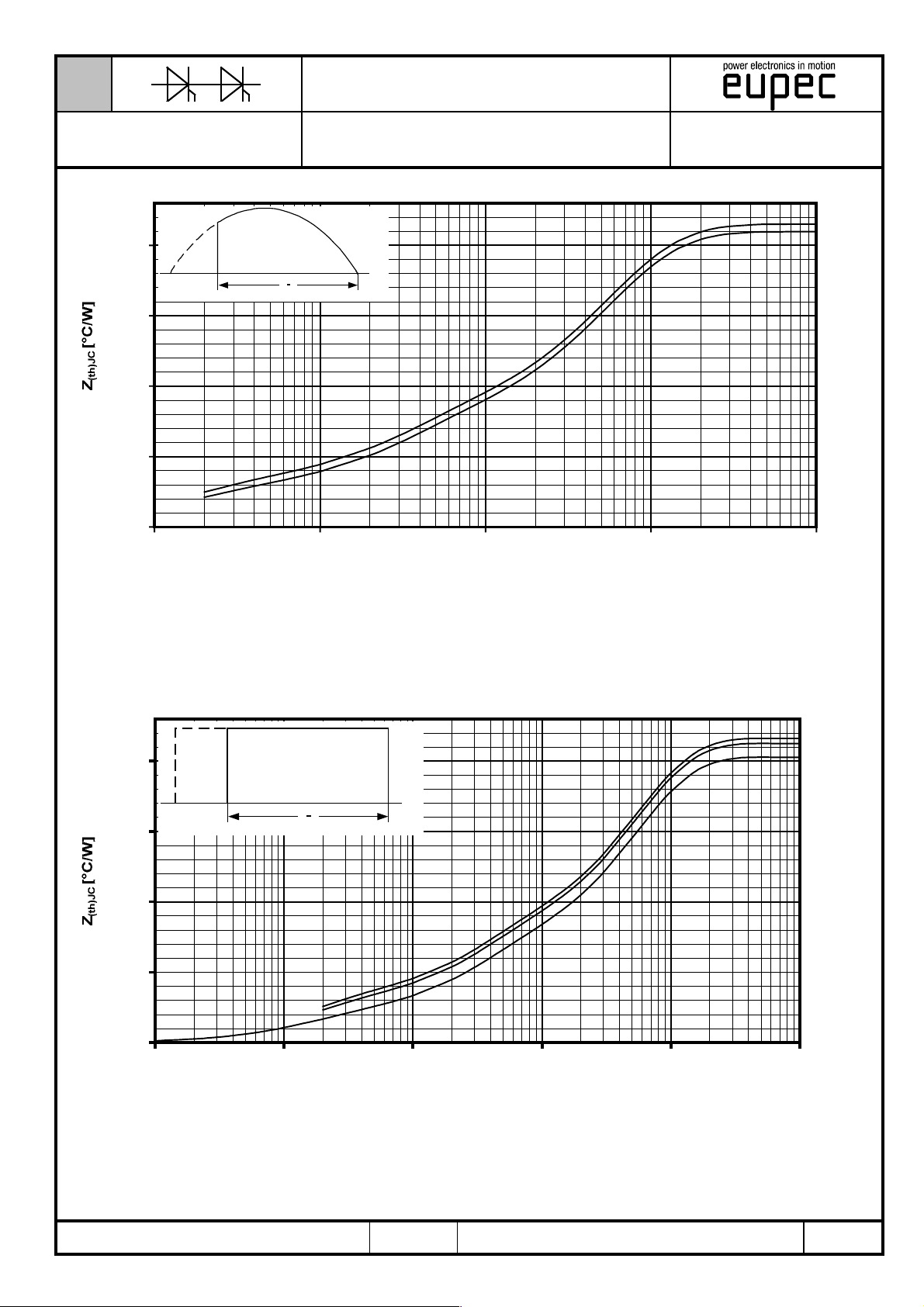
Trans. Wärmewiderstand bei Sinus
0
180°
t [s]
Θ =
60°
180°
Transienter innerer Wärmewiderstand je Zweig / Transient thermal impedance per arm Z
Sinusförmiger Strom / Sinusoidal current
Parameter: Stromflußwinkel Θ / Current conduction angle Θ
thJC
Trans. Wärmewiderstand bei Rechteck
0,040
0°
0,030
0,020
0,010
0,000
0,001 0,01 0,1 1 10 100
0
180°
t [s]
= f(t)
Θ =
60°
120°
DC
Transienter innerer Wärmewiderstand je Zweig / Transient thermal impedance per arm Z
BIP AC / 01-10-01, C. Drilling
Rechteckförmiger Strom / Rectangular current
Parameter: Stromflußwinkel Θ / Current conduction angle Θ
A 22/00
= f(t)
thJC
Seite/page
5/12
Page 6
N
Datenblatt / Data sheet
Netz-Thyristor-Modul
Phase Control Thyristor
1400
Diagramme
1200
0°
1000
[W]
TAV
800
P
600
400
200
0
0 200 400 600 800 1000
Module
TZ740N
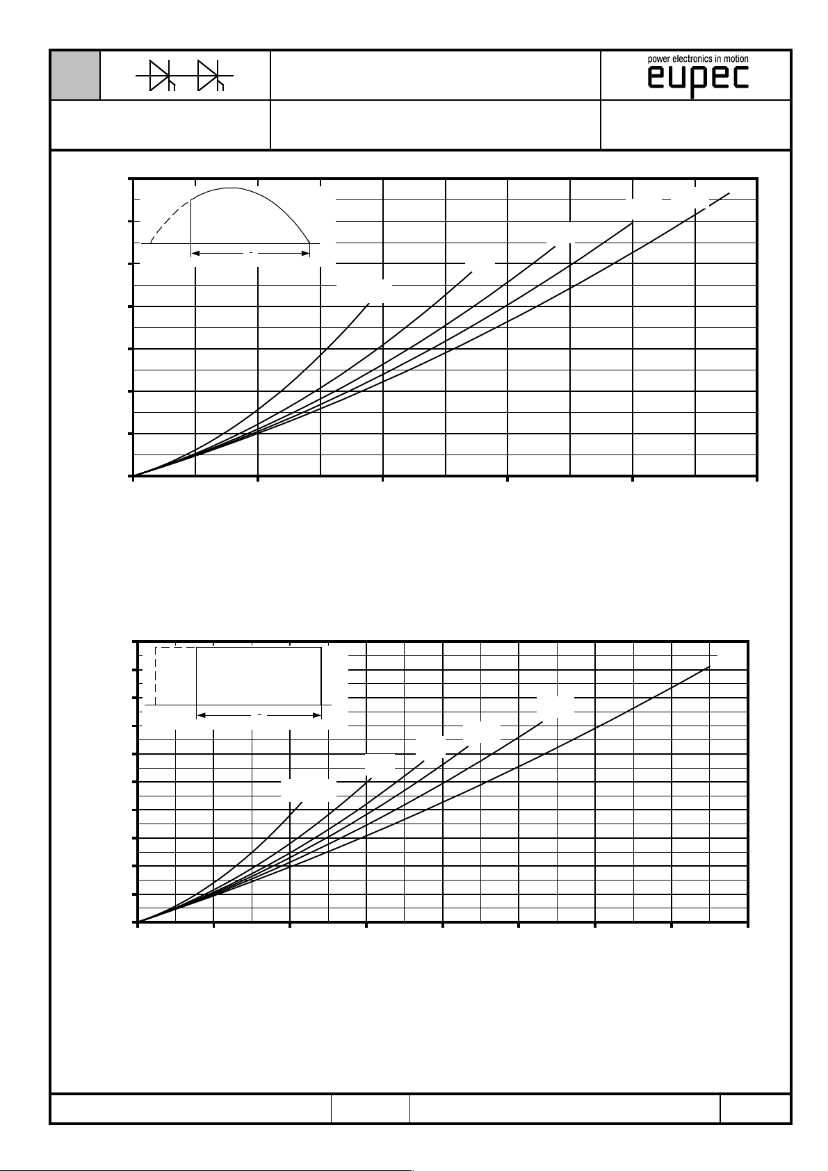
Durchgangsverluste bei Sinus
0
180°
= 30°
Q
I
TAV
60°
[A]
120°
180°
90°
[W]
TAV
P
2000
Durchlassverlustleistung je Zweig / On-state power loss per arm P
Sinusförmiger Strom / Sinusoidal current Strombelastung je Zweig / Current load per arm
Berechnungsgrundlage P
Calculation base P
Parameter: Stromflußwinkel / Current conduction angle Θ
(switching losses should be considered separately)
TAV
(Schaltverluste gesondert berücksichtigen)
TAV
Durchgangsverluste bei Rechteck
TAV
= f(I
TAV
)
1800
1600
1400
1200
1000
0°
0
180°
120°
90°
60°
= 30°
Q
180°
800
600
400
200
0
0 200 400 600 800 1000 1200 1400 1600
[A]
I
TAV
DC
Durchlassverlustleistung je Zweig / On-state power loss per arm P
Rechteckförmiger Strom / Rectangular current Strombelastung je Zweig / Current load per arm
Berechnungsgrundlage P
Calculation base P
BIP AC / 01-10-01, C. Drilling
(Schaltverluste gesondert berücksichtigen)
TAV
(switching losses should be considered separately)
TAV
Parameter: Stromflußwinkel / Current conduction angle Θ
A 22/00
TAV
= f(I
)
TAV
Seite/page
6/12
Page 7
N
Datenblatt / Data sheet
Netz-Thyristor-Modul
Phase Control Thyristor
140
120
100
[°C]
C
T
80
60
40
20
0 200 400 600 800 1000
Module
TZ740N
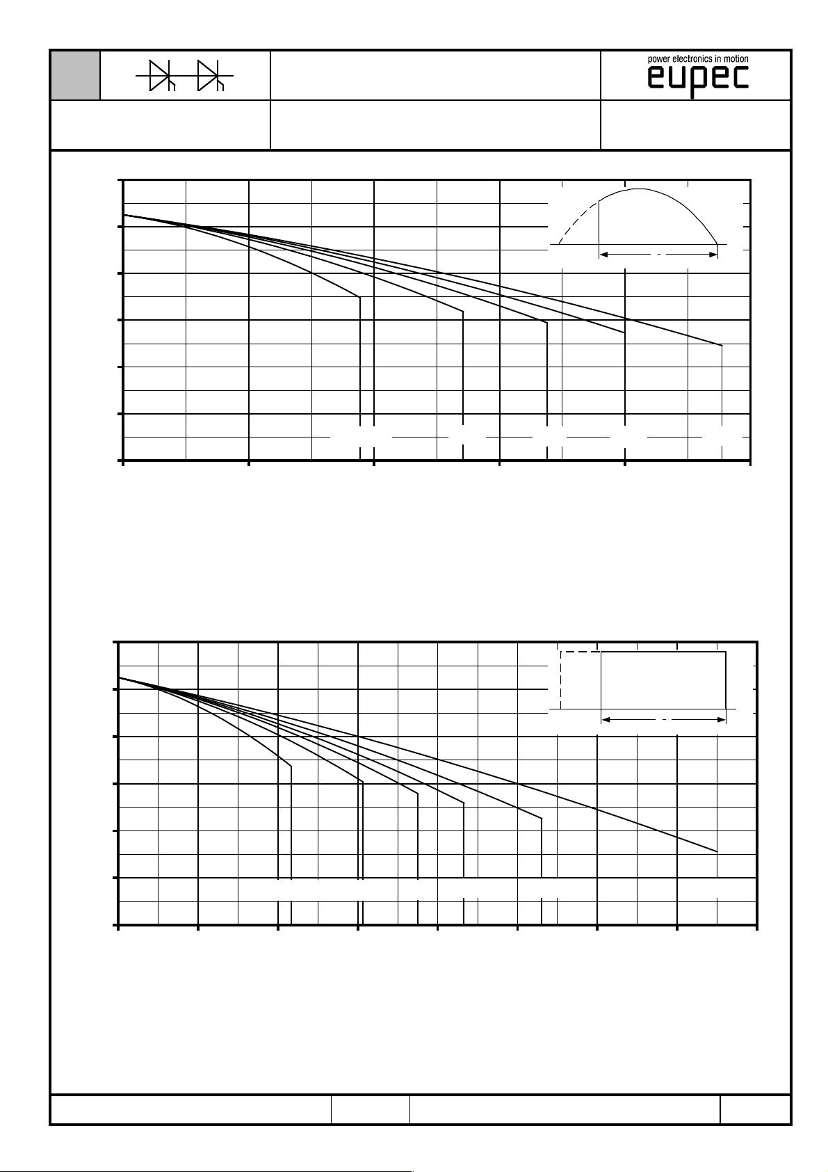
Gehäusetemperatur bei Sinus
I
TAVM
60°
[A]
= 30°
Q
90°
0°
0
120°
180°
180°
140
Höchstzulässige Gehäusetemperatur / Maximum allowable case temperature TC = f(I
Sinusförmiger Strom / Sinusoidal current Strombelastung je Zweig / Current load per arm
Berechnungsgrundlage P
Calculation base P
Parameter: Stromflußwinkel Θ / Current conduction angle Θ
(switching losses should be considered separately)
TAV
(Schaltverluste gesondert berücksichtigen)
TAV
Gehäusetemperatur bei Rechteck
TAVM
)
120
0°
0
100
[°C]
80
C
T
60
40
= 30°
Q
60°
120° 180°
90°
20
0 200 400 600 800 1000 1200 1400 1600
I
TAVM
[A]
180°
DC
Höchstzulässige Gehäusetemperatur / Maximum allowable case temperature TC = f(I
Rechteckförmiger Strom / Rectangular current Strombelastung je Zweig / Current load per arm
Berechnungsgrundlage P
Calculation base P
BIP AC / 01-10-01, C. Drilling
(Schaltverluste gesondert berücksichtigen)
TAV
(switching losses should be considered separately)
TAV
Parameter: Stromflußwinkel Θ / Current conduction angle Θ
A 22/00
)
TAVM
Seite/page
7/12
Page 8
N
Datenblatt / Data sheet
Netz-Thyristor-Modul
Phase Control Thyristor
5000
4000
3000
2000
1000
0,01
0,015
0,02
0,03
0,04
0,06
0,08
0,10
0,15
0,20
0,30
0
0 20406080100120
B2
I
D
TZ740N
+
Module
R
[°C/W]
thCA
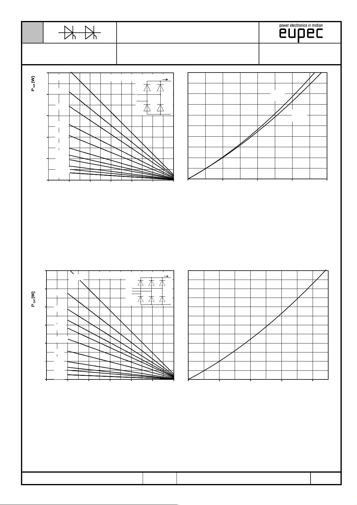
Maximaler Strom bei B2 und B6
~
-
0 500 1000 1500 2000
[°C]
T
A
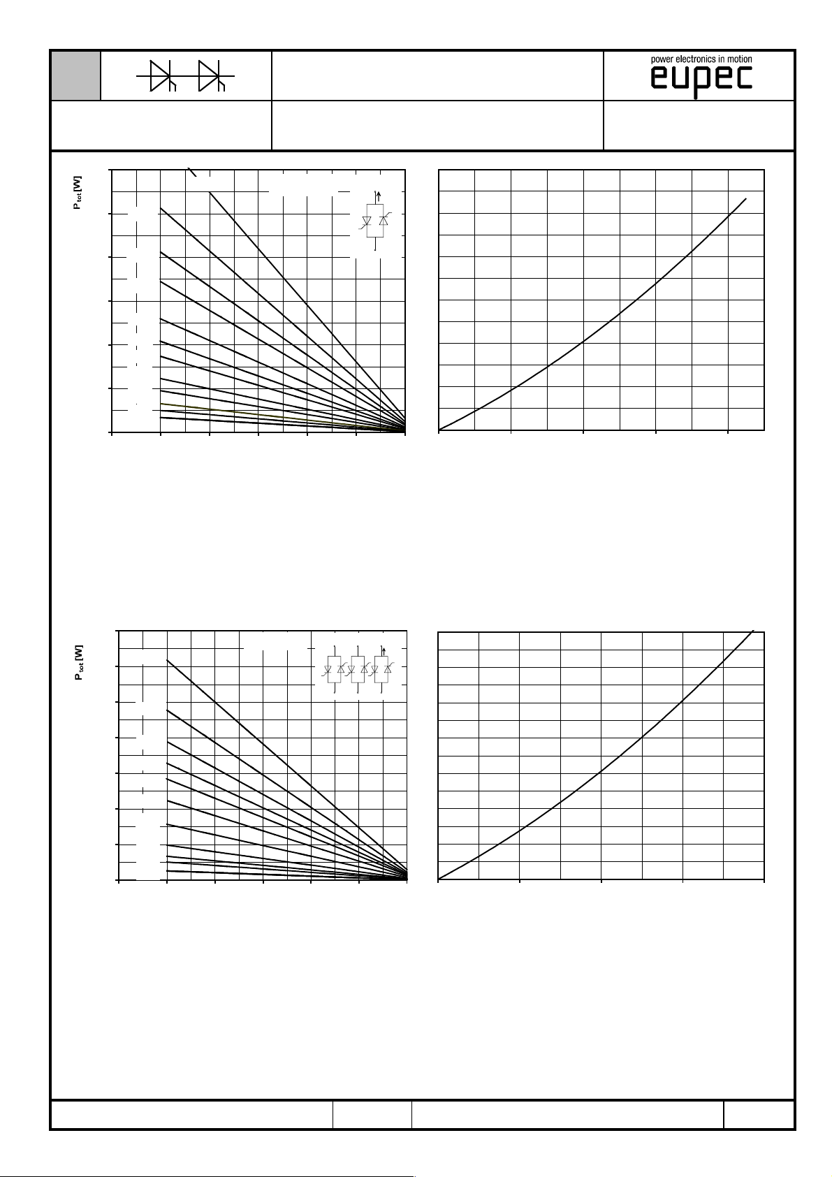
Höchstzulässiger Ausgangsstrom / Maximum rated output current I
B2- Zweipuls-Brückenschaltung / Two-pulse bridge circuit
R-Last
R-load
L-Last
L-load
[A]
I
D
D
Gesamtverlustleistung der Schaltung / Total power dissipation at circuit P
Wärmewiderstand zwischen den Gehäusen und Umgebung / Thermal resistance cases to ambient R
6000
0,01
5000
4000
3000
2000
1000
0,015
0,02
0,025
0,03
0,04
0,06
0,10
0,15
0,20
0
0 20406080100120
R
[°C/W]
thCA
3~
,
T
[°C]
A
I
B6
D
Höchstzulässiger Ausgangsstrom / Maximum rated output current I
Parameter:
+
-
0 500 1000 1500 2000
tot
thCA
[A]
I
D
D
Gesamtverlustleistung der Schaltung / Total power dissipation at circuit P
Wärmewiderstand zwischen den Gehäusen und Umgebung / Thermal resistance cases to ambient R
BIP AC / 01-10-01, C. Drilling
B6- Sechspuls-Brückenschaltung / Six-pulse bridge circuit
Parameter:
A 22/00
tot
Seite/page
thCA
8/12
Page 9
N
Datenblatt / Data sheet
Netz-Thyristor-Modul
Phase Control Thyristor
3000
2500
2000
1500
1000
0,02
0,03
0,04
0,06
0,08
0,10
0,15
0,20
500
0,30
0,40
0,60
0
0 20 40 60 80 100 120
0,01
Module
R
[°C/W]
thCA
TZ740N
W 1C
~
I
RMS
Maximaler Strom bei W1C und W3C
~
[°C]
T
A
Höchstzulässiger Effektivstrom / Maximum rated RMS current I
W1C - Einphasen-Wechselwegschaltung / Single-phase inverse parallel circuit
0 500 1000 1500 2000
I
RMS
RMS
[A]
Gesamtverlustleistung der Schaltung / Total power dissipation at circuit P
Wärmewiderstand zwischen den Gehäuse und Umgebung / Thermal resistance case to ambient R
7000
6000
5000
4000
3000
2000
1000
0,01
0,015
0,02
0,025
0,03
0,04
0,06
0,10
0,15
0,20
0,40
0
0 20406080100120
R
thCA
[°C/W]
[°C]
T
A
3C
W
~
~
~
~
I
~
~
Höchstzulässiger Effektivstrom / Maximum rated RMS current I
Parameter:
RMS
0 500 1000 1500 2000
I
RMS
RMS
tot
thCA
[A]
W3C - Dreiphasen-Wechselwegschaltung / Three-phase inverse parallel circuit
Gesamtverlustleistung der Schaltung / Total power dissipation at circuit P
Wärmewiderstand zwischen den Gehäusen und Umgebung / Thermal resistance cases to ambient R
BIP AC / 01-10-01, C. Drilling
A 22/00
Parameter:
tot
Seite/page
thCA
9/12
Page 10
N
Datenblatt / Data sheet
Netz-Thyristor-Modul
Phase Control Thyristor
100
Module
TZ740N
Steuercharakteristik
10
a
1
0,1
[mA]
10 100 1000 10000
i
G
c
b
1000
100
[µs]
gd
t
10
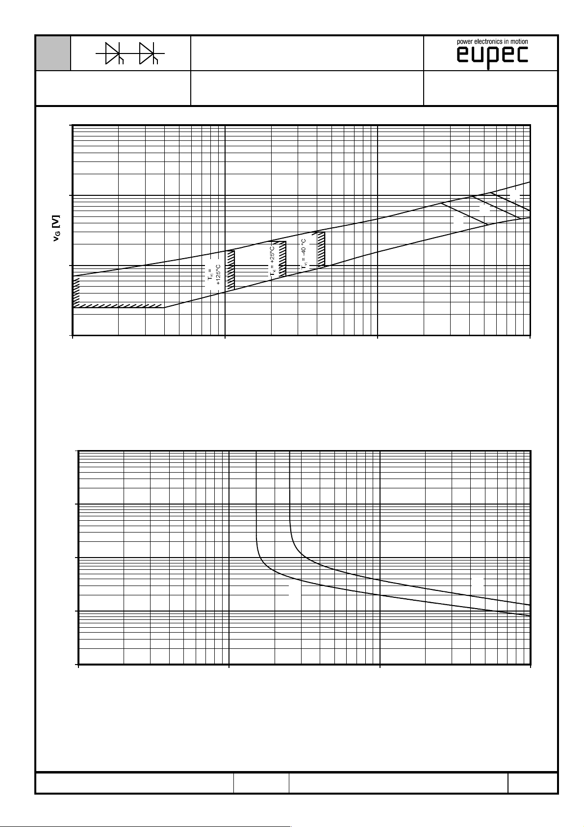
Steuercharakteristik vG = f (iG) mit Zündbereichen für VD = 6 V
Gate characteristic vG = f (iG) with triggering area for VD = 6 V
Höchstzulässige Spitzensteuerverlustleistung / Maximum rated peak gate power dissipation P
a - 20 W/10ms b - 40 W/1ms c - 60 W/0,5ms
= f (tg) :
GM
Zündverzug
b
1
a
0,1
10 100 1000 10000
BIP AC / 01-10-01, C. Drilling
i
[mA]
GM
Zündverzug / Gate controlled delay time tgd = f(iG)
T
= 25°C, diG/dt = iGM/1µs
vj
a - maximaler Verlauf / Limiting characteristic
b - typischer Verlauf / Typical characteristic
A 22/00
Seite/page
10/12
Page 11
N
Datenblatt / Data sheet
Netz-Thyristor-Modul
Phase Control Thyristor
10000
[µAs]
r
Q
1000
1 10 100
Module
TZ740N
Sperrverzögerungsladung
iFM =
2000A
1000A
500A
200A
100A
-di/dt [A/µs]
Sperrverzögerungsladung / Recovered charge Qr = f(-di/dt)
Tvj = T
Parameter: Durchlaßstrom / On-state current i
, vR ≤ 0,5 V
vjmax
, vRM = 0,8 V
RRM
RRM
TM
Grenzstrom
20.000
a
15.000
10.000
b
5.000
0
0,01 0,1 1
Ta = 25 °C
t [s]
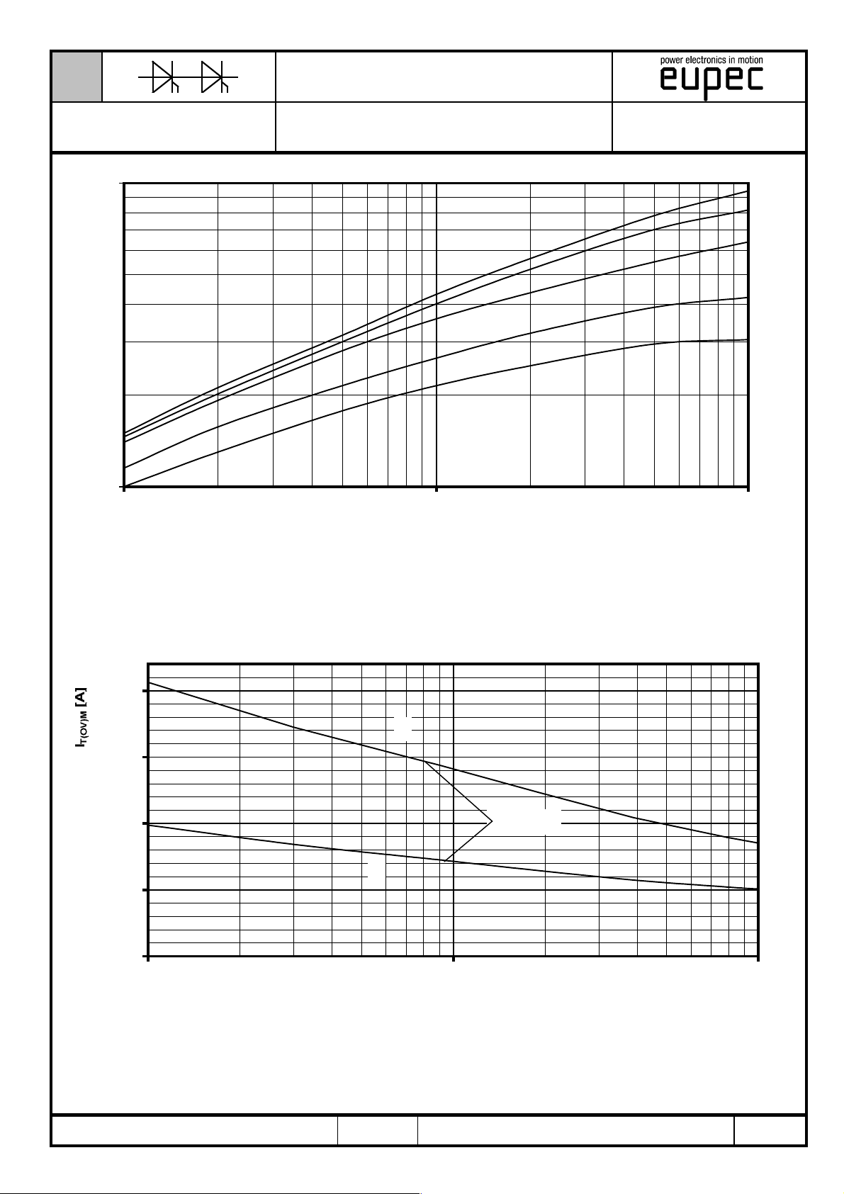
Grenzstrom / Maximum overload on-state current I
BIP AC / 01-10-01, C. Drilling
a: Leerlauf / No-load conditions
b: nach Belastung mit I
TA = 25°C, Wasserkühlung / water cooling
/ after load with I
TAVM
A 22/00
= f(t), vRM = 0,8 V
T(OV)M
TAVM
RRM
Seite/page
11/12
Page 12
N
Datenblatt / Data sheet
Netz-Thyristor-Modul
Phase Control Thyristor
16.000
14.000
12.000
10.000
8.000
6.000
4.000
2.000
0
0,01 0,1 1 10 100 1000 10000
Module
TZ740N
I
=
Überstrom
TAV (vor)
0 A
400 A
600 A
750 A
850 A
900 A
t [s]
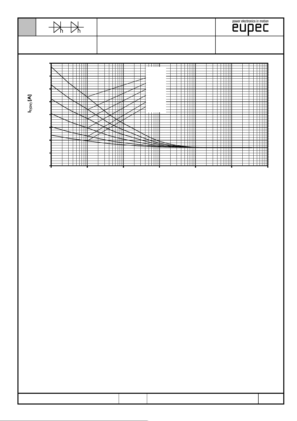
Überstrom je Zweig / Overload on-state current I
B6- Sechspuls-Brückenschaltung, 120° Rechteck / Six-pulse bridge circuit, 120° rectangular
Kühlkörper / Heatsink type KW70 ( 4l/min. ) Wasserkühlung / water cooling at T
Parameter: Vorlaststrom je Zweig / Pre-load current per arm I
T(OV)
TAV(vor)
= 25°C
A
BIP AC / 01-10-01, C. Drilling
A 22/00
Seite/page
12/12
Page 13

Nutzungsbedingungen
Die in diesem Produktdatenblatt enthaltenen Daten sind ausschließlich für technisch geschultes Fachpersonal bestimmt. Die
Beurteilung der Geeignetheit dieses Produktes für die von Ihnen anvisierte Anwendung sowie die Beurteilung der Vollständigkeit der
bereitgestellten Produktdaten für diese Anwendung obliegt Ihnen bzw. Ihren technischen Abteilungen.
In diesem Produktdatenblatt werden diejenigen Merkmale beschrieben, für die wir eine liefervertragliche Gewährleistung
übernehmen. Eine solche Gewährleistung richtet sich ausschließlich nach Maßgabe der im jeweiligen Liefervertrag enthaltenen
Bestimmungen. Garantien jeglicher Art werden für das Produkt und dessen Eigenschaften keinesfalls übernommen.
Sollten Sie von uns Produktinformationen benötigen, die über den Inhalt dieses Produktdatenblatts hinausgehen und insbesondere
eine spezifische Verwendung und den Einsatz dieses Produktes betreffen, setzen Sie sich bitte mit dem für Sie zuständigen
Vertriebsbüro in Verbindung (siehe www.eupec.com, Vertrieb&Kontakt). Für Interessenten halten wir Application Notes bereit.
Aufgrund der technischen Anforderungen könnte unser Produkt gesundheitsgefährdende Substanzen enthalten. Bei Rückfragen zu
den in diesem Produkt jeweils enthaltenen Substanzen setzen Sie sich bitte ebenfalls mit dem für Sie zuständigen Vertriebsbüro in
Verbindung.
Sollten Sie beabsichtigen, das Produkt in Anwendungen der Luftfahrt, in gesundheits- oder lebensgefährdenden oder
lebenserhaltenden Anwendungsbereichen einzusetzen, bitten wir um Mitteilung. Wir weisen darauf hin, dass wir für diese Fälle
- die gemeinsame Durchführung eines Risiko- und Qualitätsassessments;
- den Abschluss von speziellen Qualitätssicherungsvereinbarungen;
- die gemeinsame Einführung von Maßnahmen zu einer laufenden Produktbeobachtung dringend
empfehlen und gegebenenfalls die Belieferung von der Umsetzung solcher Maßnahmen abhängig
machen.
Soweit erforderlich, bitten wir Sie, entsprechende Hinweise an Ihre Kunden zu geben.
Inhaltliche Änderungen dieses Produktdatenblatts bleiben vorbehalten.
Terms & Conditions of usage
The data contained in this product data sheet is exclusively intended for technically trained staff. You and your technical departments
will have to evaluate the suitability of the product for the intended application and the completeness of the product data with respect
to such application.
This product data sheet is describing the characteristics of this product for which a warranty is granted. Any such warranty is granted
exclusively pursuant the terms and conditions of the supply agreement. There will be no guarantee of any kind for the product and its
characteristics.
Should you require product information in excess of the data given in this product data sheet or which concerns the specific
application of our product, please contact the sales office, which is responsible for you (see www.eupec.com, sales&contact). For
those that are specifically interested we may provide application notes.
Due to technical requirements our product may contain dangerous substances. For information on the types in question please
contact the sales office, which is responsible for you.
Should you intend to use the Product in aviation applications, in health or live endangering or life support applications, please notify.
Please note, that for any such applications we urgently recommend
- to perform joint Risk and Quality Assessments;
- the conclusion of Quality Agreements;
- to establish joint measures of an ongoing product survey, and that we may make delivery depended on
the realization of any such measures.
If and to the extent necessary, please forward equivalent notices to your customers.
Changes of this product data sheet are reserved.
 Loading...