

Page 1
y
Input voltage range 36…75V DC
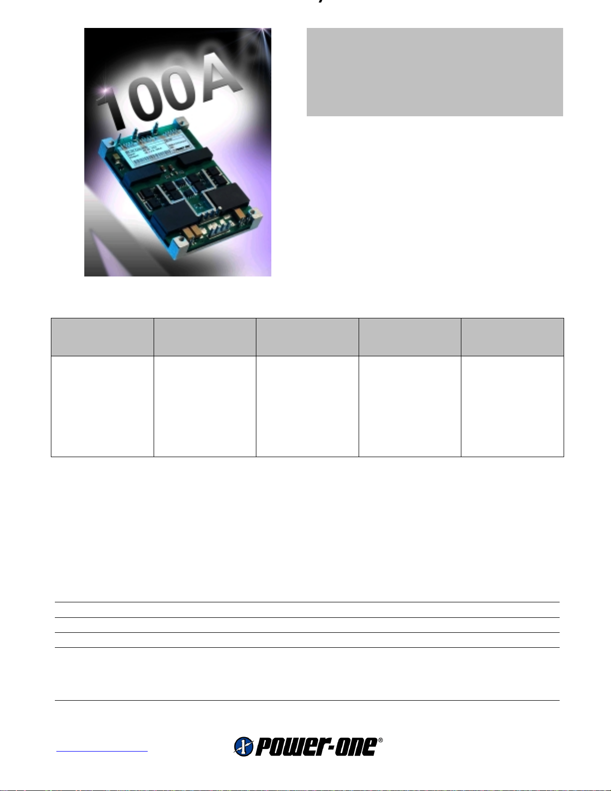
Single 80…100A output
1500V DC I/O electrical strength test voltage
Approvals: cRUus / CE (pending)
• High density design in industry standard
3
/4 brick size (2.4” x 3.45” x 0.5”)
• 100°C base plate operation
• Highly efficient topology with synchronous
rectifiers
• Output voltage trim range ±10%
• ON/OFF control
• Remote sense
• Basic insulation rating
Selection Chart
Output
U
o nom
[V DC] [A]
1.2 75
1.5 75
1.8 75
2.5 80
1.2 100
1.5 100
1.8 100
1
U
± 25%, T
i nom
I
o nom
Baseplate
Input voltage
U
i
[V DC]
36…75
36…75
36...75
36...75
36...75
36...75
36...75
=100°C, linear air flow, stand alone module
Rated power
TA = 60°C
P
o nom
90 @ 200 lfm
112 @ tbd lfm
135 @ 300 lfm
200 @ tbd lfm
120 @ 300 lfm
150 @ tbd lfm
180 @ 400 lfm
[W]
1
Type Features
TXS75ZY
TXS75ZA
TXS75ZB
Sense, Trim
Enable or
Shut-down
TXS80ZD
TXS100ZY
TXS100ZA
TXS100ZB
Purpose / Description
The TXS series is a 75 to 100 Amp, open frame, highly efficient, board mountable DC/DC converter.
The low voltage – high amperage supplies the next generation of microprocessors, gate arrays and
integrated circuits with reliable power. The TXS series features input undervoltage lockout, plus
overload and overtemperature protection and its input-output voltage combination is ideally suited for
Distributed Power Architectures (DPAs).
Input
Nominal input voltage U
i nom
Input voltage range 36...75 V DC
Transient voltage withstand survival 100V/100ms
Efficiency U
i nom
, I
o nom
, T
=25°C TXS75ZY, TXS100ZY typ. 87%
a
TXS75ZA, TXS100ZA typ. 88%
TXS75ZB, TXS100ZB typ. 89%
TXS80ZD typ. 90%
48 V DC
www.power-one.com
1
Page 2
y
Output
Output voltage setting accuracy U
Minimum load not required
Static line regulation U
Static load regulation U
Dynamic load regulation ∆Io=25A, dIo/dt=2A/µs ±10% U
Output voltage ripple and noise U
Start-up time U
Protection
Input undervoltage lockout Turn-on typ. 33V
Overload protection hic-up (self recovery) 110…130% I
OVP trip point continuous limitation, no switch off 125% U
Overtemperature shutdown with automatic restart (thermistor) typ. 115°C
Control
/SD, inverse shutdown input TTL-compatible, unit disabled when active low (<1.5V)
Trim input for U
o
, 50 % I
i nom
...U
i min
i nom
i nom
i max
, 10...100 % I
, I
o nom
, Tc = 25°C ±1% U
o nom
, 50% I
o nom
o nom
±0.5% U
±0.5% U
o nom
o nom
o nom
o nom
, 100µs
, 20 MHz bandwidth TXS100ZY/TXS100ZA 50 mVpp
TXS100ZB/TXS80ZD 100 mVpp
i nom
, I
o nom
10ms
Turn-off typ. 31V
o nom
o nom
0.6V / 20kΩ 90…110% U
o nom
Safety and EMC
Planned approvals EN 60950, UL 1950, CSA 22.2 No. 950
I/O insulation EN60950, base plate floating Basic
Electric strength test voltage I/Case, I/O, O/Case 1.5 kV DC
Electrostatic discharge IEC/EN 61000-4-2, level 3 (contact/air) 4/8 kV, criterion B
Electromagnetic field IEC/EN 61000-4-3, level 2 3 V/m, criterion A
Electr. fast transients/burst IEC/EN 61000-4-4, tbd. tbd., criterion B
Electromagnetic emissions CISPR 22/EN 55022, conducted (with external filter) class B
CISPR 22/EN 55022, radiated (with external filter) class B
Environmental specifications
Operating temperature T
BP
Storage temperature non operational -40...100°C
Damp heat IEC/EN 60068-2-3, 93%, 40°C 56 days
Shock IEC/EN 60068-2-27, 11 ms tbd g
Bump IEC/EN 60068-2-29, 6 ms tbd g
Sinusoidal vibration IEC/EN 60068-2-6, 8.2…58.1/58.1…500 Hz tbd gn/tbd g
Random vibration IEC/EN 60068-2-64, 10…200/200...2000 Hz tbd/tbd g2/Hz
MTBF MIL-HDBK-217F Notice 2, GB, 60°C 1.1 Mio h
U
i nom
, I
, base plate temperature -40...100°C
o nom
n
n
n
2
www.power-one.com
Page 3
y
Mechanics
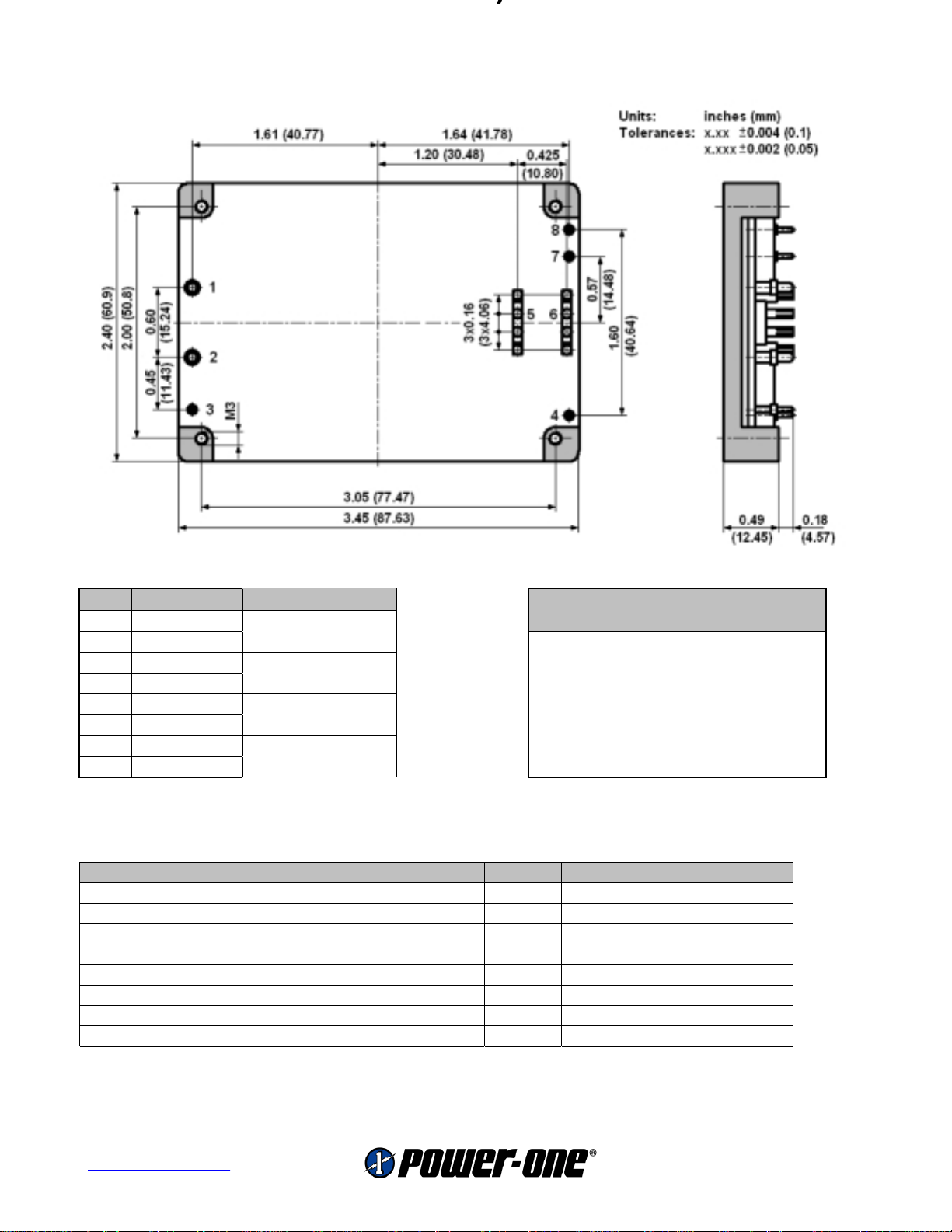
Print mountable industry standard 3/4 brick (2.4 x 3.45 x 0.5 inch3)
Pin Function
1 Vi- (Baseplate to ambient)
2 Vi+
3 ON/OFF 200 lfm 2.2 K/W
4 Sense+
5 Vo- 400 lfm 1.4 K/W
6 Vo+
7 Trim
8 Sense-
_ inch (mm)
0.08 ± 0.002
(2.03 ± 0.05)
0.04 ± 0.002
(1.02 ± 0.05)
4x 0.085 ± 0.002
(4x 2.16 ± 0.05)
0.04 ± 0.002
(1.02 ± 0.05)
100 lfm 2.8 K/W
300 lfm 1.7 K/W
Note: Thermal impedance data is dependent on
many environmental factors. The exact thermal
performance should be validated for specific
application. The figure is for a stand-alone module.
Thermal Impedance
Options / Accessories
Option / Accessory Suffix Remarks
Negative Logic (unit works when active low) N
0.24’’ (6.1mm) Pin Lengths tbd Contact factory
0.24" (6.1mm) Horizontal Heatsink 1H Includes Thermal Pad
0.24" (6.1mm) Vertical Heatsink 1V Includes Thermal Pad
0.45" (11.4mm) Horizontal Heatsink 2H Includes Thermal Pad
0.45" (11.4mm) Vertical Heatsink 2V Includes Thermal Pad
0.95" (24.1mm) Horizontal Heatsink 3H Includes Thermal Pad
0.95" (24.1mm) Vertical Heatsink 3V Includes Thermal Pad
Subject to change without notice.
www.power-one.com
3
 Loading...