

Page 1

Quick Start Guide
TWR-K21D50M
Low-Power 32-bit ARM® Cortex™-M4 MCUs
with High-Precision Analog, Connectivity
and Security
TOWER SYSTEM
Page 2
Quick Start Guide
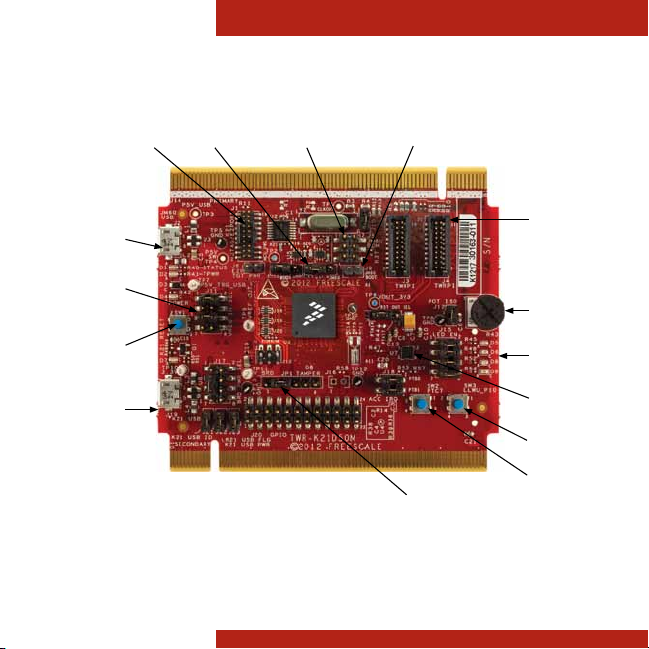
Get to Know the TWR-K21D50M
Power/OSJTAG
Micro-USB
Regulator
Option
Selector
RESET
K21
Micro-USB
2
JM60 BDMVBAT OptionsJTAG
Figure 1: Front side of TWR-K21D50M module (TWRPI devices not shown).
JM60 Bootloader
Enable
Tamper Pins
GeneralPurpose
TWRPI Plug-In
Potentiometer
LEDs
Accelerometer
SW3
SW2
Page 3
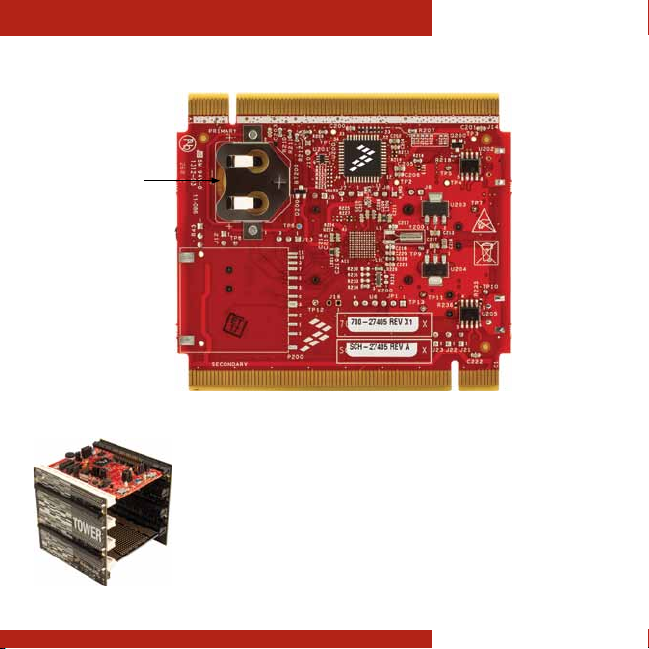
Battery
Receptacle
TOWER SYSTEM
TWR-K21D50M
Freescale Tower System
The TWR-K21D50M MCU module is designed to work either in stand-alone
mode or as part of the Freescale Tower System, a modular development platform
that enables rapid prototyping and tool re-use through reconfigurable hardware.
Begin constructing your Tower System today by visiting freescale.com/Tower for
additional Tower System MCU modules and compatible peripherals.
3
Page 4

Quick Start Guide
TWR-K21D50M Features
• MK21DN512VMC5 MCU (50 MHz, 512 KB Flash,
64 KB RAM, USB OTG, tamper detection, encryption,
low power, 121 MBGA)
• Dual-role USB interface with Micro-AB USB connector
• On-board open source JTAG (OSJTAG) circuit with virtual
serial port
• General-purpose Tower plug-in (TWRPI) socket
• Three-axis accelerometer (MMA8451Q)
• Four user-controlled status LEDs
• Push buttons for GPIO interrupts and MCU reset
• Potentiometer
• Independent, battery-operated power supply for
real-time clock and tamper detection modules
4
Page 5

TOWER SYSTEM
Step-by-Step Installation Instructions
Install the
1
Software and Tools
Install the P&E Micro Kinetis Tower
toolkit. The toolkit includes the
OSJTAG and USB to serial drivers.
Configure the
2
Hardware
Install the included battery into the
VBAT (RTC) battery holder. Then,
connect one end of the USB cable
to the PC and the other end to the
Power/OSJTAG micro-B connector
on the TWR-K21D50M module.
Allow the PC to automatically
configure the USB drivers if needed.
Tilt the
3
Board
Tilt the board side to side to see
the LEDs on D5, D6, D8 and D9
light up as it is tilted. While the
board is held flat, press SW2 and
SW3 to toggle LEDs D5 and D9,
respectively.
5
Page 6

Quick Start Guide
Download the TWR-
4
K21D50M User Manual
and Demonstration Labs
Download the TWR-K21D50M user
manual and demonstration labs at
freescale.com/TWR-K21D50M.
Download the Freescale
5
CodeWarrior IDE and
MQX™ RTOS
Download the Freescale
CodeWarrior IDE and MQX RTOS
by clicking the relevant links at
freescale.com/CodeWarrior and
freescale.com/MQX.
TWR-K21D50M Jumper Options
The following is a list of all jumper options on the TWR-K21D50M. The default installed jumper
settings are indicated by white text within the red boxes.
Jumper Option Setting Description
J8 MCU Power
Connection
J7 VBAT Power
Source
J6 JTAG Board
Power
Selection
J9 OSJTAG
Bootloader
Selection
J17 V_BRD Power
Source
(Board Power
Selector)
6
1-2 Connect on-board 3.3 V or 1.8 V supply (V_BRD) to MCU VDD
2-3 Connect K21 USB regulator output to MCU VDD
1-2 Connect VBAT to on-board 3.3 V or 1.8 V supply
2-3 Connect VBAT to the higher voltage between MCU supply (MCU_PWR)
or coin cell supply (VBATD)
ON Connect OSJTAG 5 V output (P5V_TRG_USB) to JTAG port (supports
powering board from JTAG pod supporting 5 V supply output)
OFF Disconnect OSJTAG 5 V output (P5V_TRG_USB) from JTAG port
ON OSJTAG bootloader mode (OSJTAG firmware reprogramming)
OFF Debugger mode
1-2 Connect K21 USB regulator output (VOUT_3V3) to
on-board supply (V_BRD)
3-5 Connect 3.3 V on-board regulator output (P3V3) to
on-board supply (V_BRD)
5-7 Connect 1.8 V on-board regulator output (P1V8) to
on-board supply (V_BRD)
Page 7

TOWER SYSTEM
TWR-K21D50M Jumper Options (continued)
Jumper Option Setting Description
J11 VREG IN
Selector
J21 USB ID
Connection
J22 USB Power
Enable
J23 USB Over-
Current Flag
J10 General
Purpose
TWRPI
V_BRD
Power Enable
J18 Accelerometer
IRQ
Connection
J12 Potentiometer
Connection
J15 LED
Connections
J13 GPIO RESET_
OUT_B
Connection
1-2 OSJTAG 5V output (P5V_TRG_USB)
connected to on-board regulator input (VREG_IN)
5-6 VBUS signal on micro-USB connector J19 connects to
K21_VREGIN to allow stand-alone USB operation
6-8 VBUS signal from Tower Elevator connector connects to
K21_VREGIN to allow USB operation with complete Tower System
ON Connect PTD7 to USB ID pin
OFF Disconnect PTD7 from USB ID pin
ON Connect PTC9 to USB power enable on power switch MIC2026
OFF Disconnect PTC9 from USB power enable on power switch MIC2026
ON Connect PTC8 to over-current flag on power switch MIC2026
OFF Disconnect PTC8 from over-current flag on power switch MIC2026
ON Connect on-board 1.8 V or 3.3 V supply (V_BRD) to
TWRPI 3-V power (GPT_VBRD)
OFF Disconnect from-board 1.8 V or 3.3 V supply (V_BRD) to
TWRPI 3-V power (GPT_VBRD)
1-2 Connect PTB0 to INT1 pin of accelerometer
3-4 Connect PTB1to INT2 pin of accelerometer
OFF Disconnect PTB0 and/or PTB1 from INT1 and/or INT2 of accelerometer
ON Connect potentiometer to ADC0_SE12
OFF Disconnect potentiometer from ADC0_SE12
1-2 Connect PTD4 to green LED (D5)
3-4 Connect PTD5 to yellow LED (D6)
5-6 Connect PTD6 to red LED (D8)
7-8 Connect PTD7 to blue LED (D9)
OFF Disconnect PTD[4:7] from associated LED
1-2 Connect PTA14 to RESET_OUT_B signal
2-3 Connect PTA17 to RESET_OUT_B signal
OFF Leave RESET_OUT_B signal disconnected
7
Page 8

Quick Start GuideQuick Start Guide
Visit freescale.com/TWR-K21D50M,
freescale.com/K20 or freescale.com/Kinetis
for information on the TWR-K21D50M module,
including:
• TWR-K21D50M user guide
• TWR-K21D50M schematics
• Tower System fact sheet
Support
Visit freescale.com/support for a list of phone
numbers within your region.
Warranty
Visit freescale.com/warranty for complete
warranty information.
For more information, visit freescale.com/Tower
Join the online Tower community at towergeeks.org
Freescale, the Freescale logo, CodeWarrior and Kinetis are trademarks of
Freescale semiconductor, Inc., Reg. U.S. Pat. & Tm. Off. All other product
or service names are the property of their respective owners.
© 2012 Freescale Semiconductor, Inc.
Doc Number: K21D50MQSG REV 0
Agile Number: 926-27405 REV A
 Loading...