

Page 1
TSL260, TSL261, TSL262
IR LIGHTTOVOLTAGE OPTICAL SENSORS
TAOS021 – MAY 2000
Integral Visible Light Cutoff Filter
Monolithic Silicon IC Containing
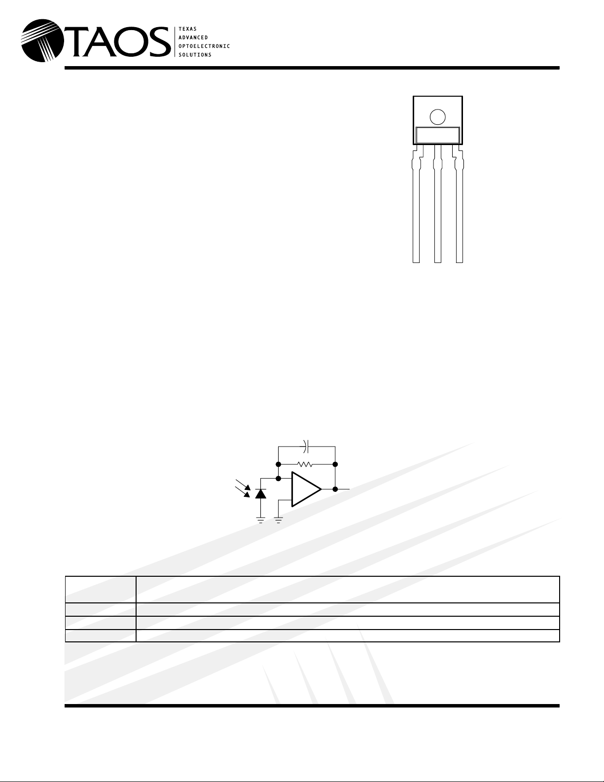
PACKAGE
(FRONT VIEW)
Photodiode, Operational Amplifier, and
Feedback Components
Converts Light Intensity to Output Voltage
321
High Irradiance Responsivity Typically
42 mV/(µW/cm2) at λp = 940 nm (TSL260)
Low Dark (Offset) Voltage . . . 10 mV
Max at 25°C, VDD = 5 V
Single-Supply Operation
Wide Supply Voltage Range ...3 V to 9 V
Low Supply Current . . . 800 µA Typical at
VDD = 5 V
Advanced Linear CMOS Technology
GND
Description
The TSL260, TSL261, and TSL262 are light-to-voltage optical sensors, each combining a photodiode and a
transimpedance amplifier (feedback resistor = 16 MΩ, 8 MΩ, and 2 MΩ, respectively) on a single monolithic
integrated circuit. The output voltage is directly proportional to the infrared light intensity (irradiance) on the
photodiode. The TSL260, TSL261, and TSL262 are manufactured using advanced linear CMOS silicon-gate
technology, which provides good amplifier offset-voltage stability and low power consumption.
DD
OUTV
Functional Block Diagram
–
+
Terminal Functions
TERMINAL
NAME NO.
GND 1 Ground (substrate). All voltages are referenced to GND.
OUT 3 Output voltage
V
DD
2 Supply voltage
Voltage
Output
DESCRIPTION
www.taosinc.com
Texas Advanced Optoelectronic Solutions Inc.
800 Jupiter Road, Suite 205 Plano, TX 75074 (972) 673-0759
Copyright 2000, TAOS Inc.
1
Page 2
TSL260, TSL261, TSL262
TEST
VOOut ut voltage
V
of out ut voltage (VO)
IR LIGHTTOVOLTAGE OPTICAL SENSORS
TAOS021 – MAY 2000
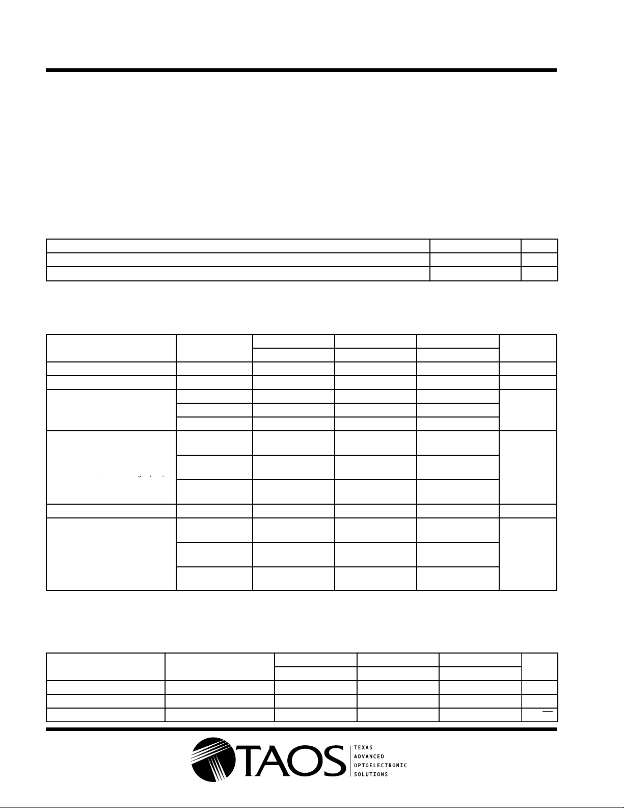
Absolute Maximum Ratings over operating free-air temperature range (unless otherwise noted)
Supply voltage, VDD (see Note 1) 10 V. . . . . . . . . . . . . . . . . . . . . . . . . . . . . . . . . . . . . . . . . . . . . . . . . . . . . . . . . . .
Output current, IO ±10 mA. . . . . . . . . . . . . . . . . . . . . . . . . . . . . . . . . . . . . . . . . . . . . . . . . . . . . . . . . . . . . . . . . . . . . .
Duration of short-circuit current at (or below) 25°C (see Note 2) 5 s. . . . . . . . . . . . . . . . . . . . . . . . . . . . . . . . . .
Operating free-air temperature range, TA –25°C to 85°C. . . . . . . . . . . . . . . . . . . . . . . . . . . . . . . . . . . . . . . . . . . .
Storage temperature range –25°C to 85°C. . . . . . . . . . . . . . . . . . . . . . . . . . . . . . . . . . . . . . . . . . . . . . . . . . . . . . . .
Lead temperature 1,6 mm (1/16 inch) from case for 10 seconds 240°C. . . . . . . . . . . . . . . . . . . . . . . . . . . . . . .
NOTES: 1. All voltages are with respect to GND.
Recommended Operating Conditions
Supply voltage, V
Operating free-air temperature, T
Electrical Characteristics at VDD = 5 V , TA = 25°C, λp = 940 nm, RL = 10 kΩ (unless otherwise noted)
(see Note 3)
V
V
V
N
I
DD
NOTES: 3. The input irradiance Ee is supplied by a GaAs infrared-emitting diode with λp = 940 nm.
2. Output may be shorted to either supply.
DD
A
PARAMETER
DARK
OM
O
e
Dark voltage Ee = 0 3 10 3 10 3 10 mV
Maximum output Ee = 2.6 mW/cm
Output voltage
Temperature coefficient
of output voltage (VO)
Irradiance responsivity See Note 4 42 23 3.8 mV/(µW/cm2)
Supply current
4. Irradiance responsivity is characterized over the range VO = 0.05 to 3 V.
TEST
CONDITIONS
Ee = 48 µW/cm
Ee = 87 µW/cm
Ee = 525 µW/cm
Ee = 48 µW/cm2,
TA = 0°C to 70°C
Ee = 87 µW/cm2,
TA = 0°C to 70°C
Ee = 525 µW/cm2,
TA = 0°C to 70°C
Ee = 48 µW/cm
No load
Ee = 87 µW/cm
No load
Ee = 525 µW/cm
No load
2
2
2,
2,
2
2
2,
TSL260 TSL261 TSL262
MIN TYP MAX MIN TYP MAX MIN TYP MAX
3.1 3.5 3.1 3.5 3.1 3.5 V
1 2 3
900 1600
±1
1 2 3
±1
900 1600
MIN NOM MAX UNIT
3 5 9 V
0 70 °C
UNIT
V
1 2 3
mV/°C
±1
µA
900 1600
Operating Characteristics at TA = 25°C (see Figure 1)
t
r
t
f
VnOutput noise voltage VDD = 5 V, f = 20 Hz 0.6 0.5 0.4 µV/√Hz
Copyright 2000, TAOS Inc.
2
PARAMETER TEST CONDITIONS
Output pulse rise time VDD = 5 V, λp = 940 nm 360 90 7 µs
Output pulse fall time VDD = 5 V, λp = 940 nm 360 90 7 µs
TSL260 TSL261 TSL262
MIN TYP MAX MIN TYP MAX MIN TYP MAX
www.taosinc.com
UNIT
Page 3
Pulse
Generator
IRED
(see Note A)
IR LIGHTTOVOLTAGE OPTICAL SENSORS
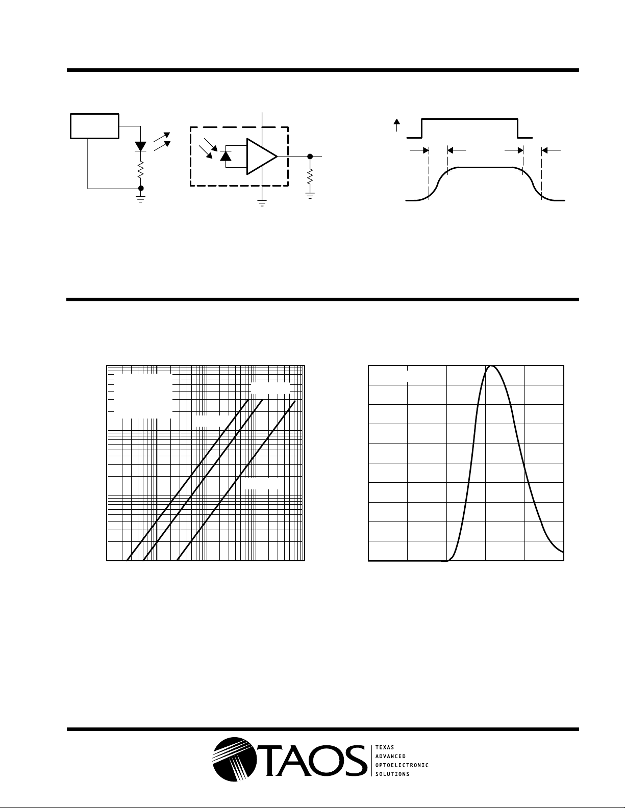
PARAMETER MEASUREMENT INFORMATION
V
TSL26x
TEST CIRCUIT
DD
2
–
+
3
1
R
Output
L
(see Note B)
Input
Output
E
e
TSL260, TSL261, TSL262
TAOS021 – MAY 2000
t
r
90%
10%
VOLTAGE WAVEFORM
90%
10%
t
f
NOTES: A. The input irradiance is supplied by a pulsed GaAs infrared-emitting diode with the following characteristics: λp = 940 nm, tr < 1 µs,
tf < 1 µs.
B. The output waveform is monitored on an oscilloscope with the following characteristics: tr < 100 ns, Zi ≥ 1 MHz, Ci ≤ 20 pF.
Figure 1. Switching Times
TYPICAL CHARACTERISTICS
OUTPUT VOLTAGE
vs
PHOTODIODE SPECTRAL RESPONSE
1
TA = 25°C
0.9
0.8
0.7
0.6
0.5
0.4
0.3
0.2
10
1
– Output Voltage – V
0.1
O
V
VDD = 5 V
λp = 940 nm
No Load
TA = 25°C
IRRADIANCE
TSL261
TSL260
TSL262
Relative Responsivity
0.01
0.1 1 10 100
www.taosinc.com
0.1
0
600 700 800 900
λ – Wavelength – nm
E
– Irradiance – µW/cm
e
2
1000
Figure 2 Figure 3
1000
Copyright 2000, TAOS Inc.
1100
3
Page 4
TSL260, TSL261, TSL262
IR LIGHTTOVOLTAGE OPTICAL SENSORS
TAOS021 – MAY 2000
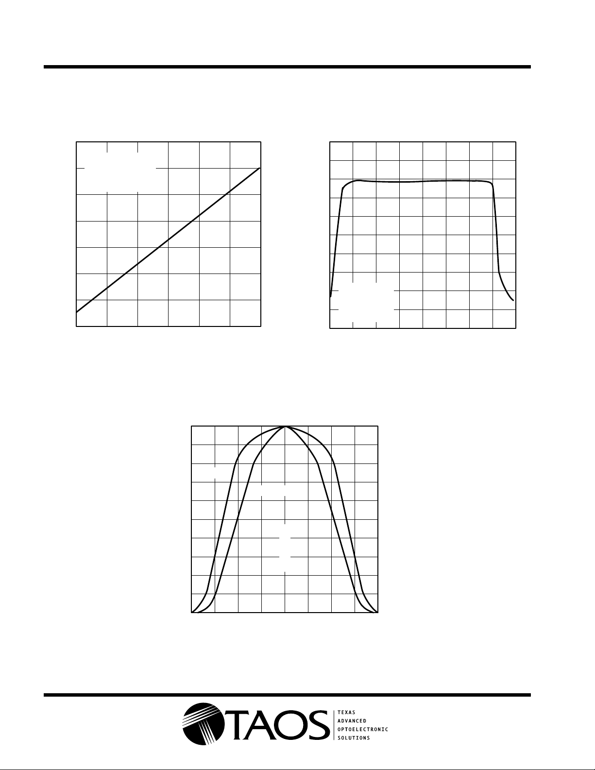
TYPICAL CHARACTERISTICS
9
8
7
6
5
– Maximum Output Voltage – V
4
OM
V
3
2
HIGH-LEVEL OUTPUT VOLTAGE
vs
SUPPLY VOLTAGE
Ee = 2.6 mW/cm
λp = 940 nm
RL = 10 kΩ
TA = 25°C
2
789
VDD – Supply Voltage – V
Figure 4 Figure 5
SUPPLY CURRENT
vs
OUTPUT VOLTAGE
0.8
0.6
0.4
– Supply Current – mA
DD
I
10456
VDD = 5 V
0.2
No Load
(RL = ∞)
TA = 25°C
0
012 314
VO – Output Voltage – V
NORMALIZED OUTPUT VOLTAGE
ANGULAR DISPLACEMENT
1
0.8
TSL260
TSL261, 262
0.6
0.4
Normalized Output Voltage
0.2
0
80° 60° 40° 20° 0° 80°60°40°20°
θ – Angular Displacement
vs
Optical Axis
Figure 6
Copyright 2000, TAOS Inc.
4
www.taosinc.com
Page 5
IR LIGHTTOVOLTAGE OPTICAL SENSORS
APPLICATION INFORMATION
V
DD
TSL260, TSL261, TSL262
TAOS021 – MAY 2000
2
TSL26x
Sensor
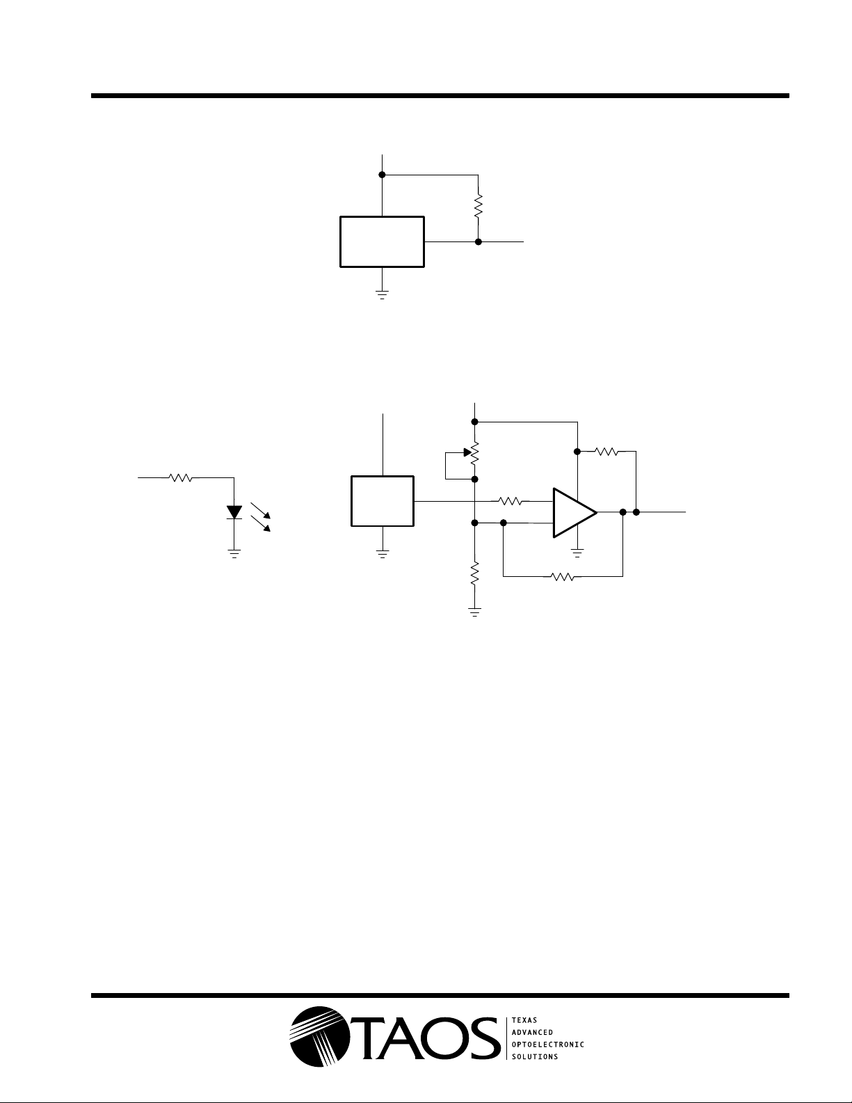
NOTE A: Pullup resistor extends linear output range to near VDD with minimal (several millivolts typical) effect on V
at low VDD (3 V to 5 V).
3
1
Figure 7. Pullup for Increased V
5 V
TSL261
Sensor
2
3
1
15 kΩ
5 V
100 Ω
OP240
†
RP = 100 kΩ
5 V
50-kΩ
Threshold
10 kΩ
Output
OM
2
3
LM393
–
+
15 kΩ
4.7 kΩ
8
4
1
; particularly useful
DARK
Output
†
OPTEK part number
NOTE A: Output goes high when beam is interrupted; working distance is several inches or less. Intended for use as optical-interrupter switch
or reflective-object sensor.
Figure 8. Short-Range Optical Switch With Hysteresis
www.taosinc.com
Copyright 2000, TAOS Inc.
5
Page 6
TSL260, TSL261, TSL262
IR LIGHTTOVOLTAGE OPTICAL SENSORS
TAOS021 – MAY 2000
APPLICATION INFORMATION
5 V
†
BN301
27 kΩ
3 kΩ
0.01 µF
†
Stanley part number
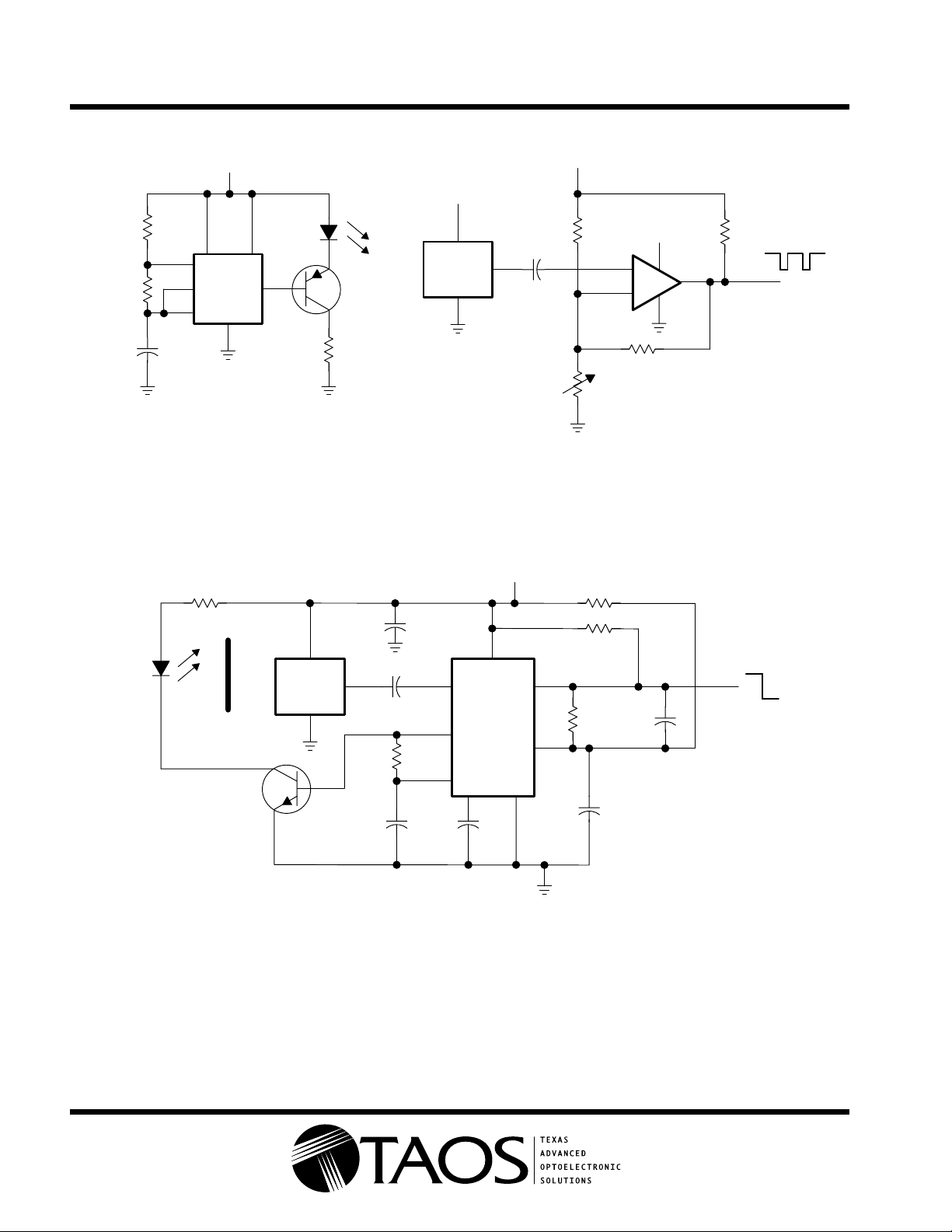
NOTE A: Output pulses low until beam is interrupted. Useful range is 1 ft to 20 ft; can be extended with lenses. This configuration is suited
for object detection, safety guards, security systems, and automatic doors.
7
6
2
4
TLC555
8
3
2N3906
1
18 Ω
5 V
TSL262
Sensor
2
3
0.01 µF
1
5 V
50 kΩ
2
–
3
+
TLC372
100 kΩ
15-kΩ
Threshold
5 V
4.7 kΩ
8
1
4
Output
Figure 9. Pulsed Optical-Beam Interrupter
100 Ω
6 V
560 kΩ
0.1 µF
0.01 µF
3
5
6
27
1 µF0.1 µF
4
NE567
+
1 kΩ
8
270 kΩ
+
0.1 µF
4.7 µF
1
TSL260
Sensor
2
3
1
10 kΩ
†
OP295
or
‡
BN301
Light
Shield
2N3904
†
OPTEK part number
‡
Stanley part number
NOTE A: Output goes low when light pulses from emitter are reflected back to sensor. Range is 6 in to 18 in depending upon object
reflectance. Useful for automatic doors, annunciators, object avoidance in robotics, automatic faucets, and security systems.
Figure 10. Proximity Detector
Copyright 2000, TAOS Inc.
6
www.taosinc.com
Page 7
S1
TSL260, TSL261, TSL262
IR LIGHTTOVOLTAGE OPTICAL SENSORS
TAOS021 – MAY 2000
APPLICATION INFORMATION
Freq
Trim
9 V
6 V
IN
U4
TSL260
Sensor
OUT
COM
1
7.5 kΩ
4.7 kΩ
0.1 µF
2
R5
+
R6
C2
R1
680 Ω
7
6
2
C1
1 µF
3
C5
0.1 µF
3
5
6
2
+ +
C3
1 µF
84
U1
TLC555
6 V
4
U2
NE567
7
C4
4.7 µF
1
8
1
R3
22 Ω
3
R2
1 kΩ
5
TRANSMITTER
R7
4.7 kΩ
6 V
4
1
16
2
1
6 V
R8
300 Ω
1
2
PRE VCCCLR
J
1/2 SN74HC76
CLK
K
U3
TIL3010
52
U5
GND
13
3
Q1
2N3904
6
4
3
Q
AC Load
R4
180 Ω
15
J1
1
R9
1 kΩ
D1
†
BN301
To Sensor
2
1
2
3
120 V
60 Hz
Q2
TIC225C
3
Q3
2N3904
RECEIVER
†
OPTEK part number
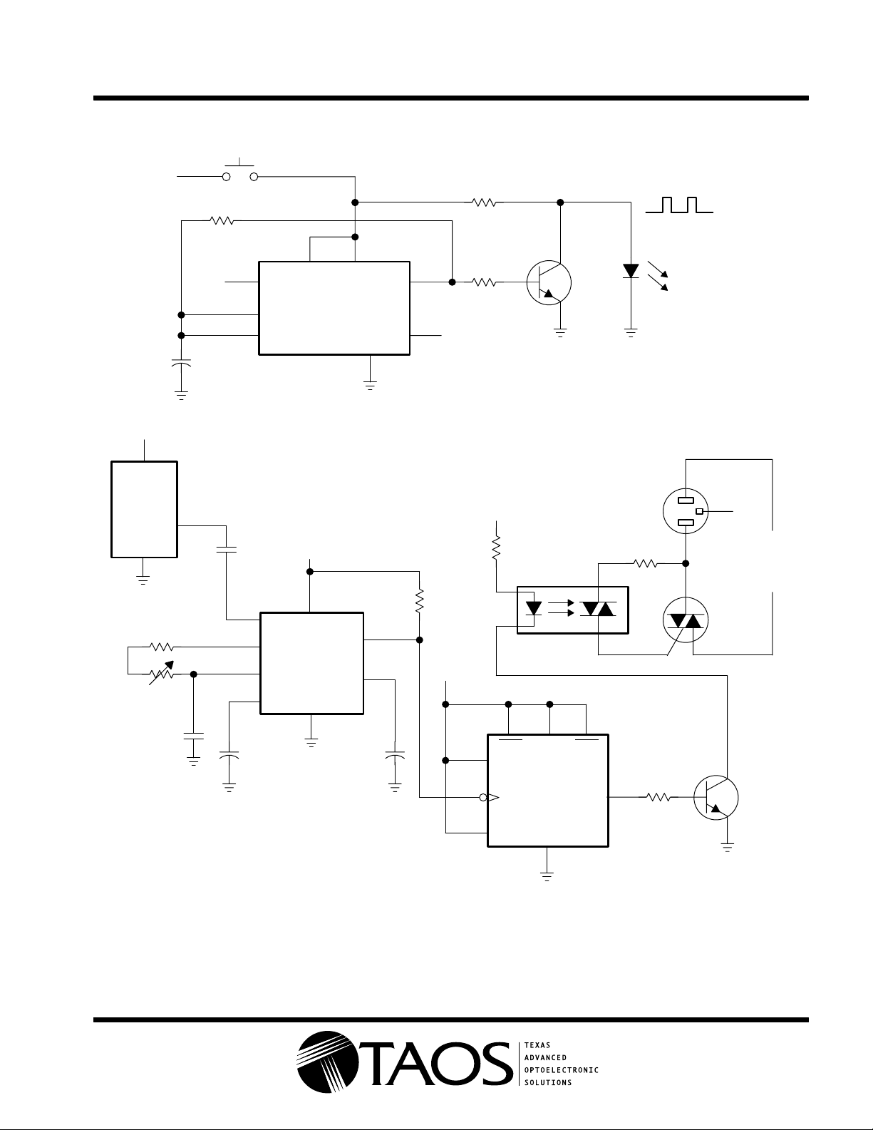
NOTE A: Single-channel remote control can be used to switch logic or light dc loads by way of U5 or ac loads by way of the optocoupler and
triac as shown. Applications include ceiling fans, lamps, electric heaters, etc.
Figure 11. IR Remote Control
www.taosinc.com
Copyright 2000, TAOS Inc.
7
Page 8
TSL260, TSL261, TSL262
IR LIGHTTOVOLTAGE OPTICAL SENSORS
TAOS021 – MAY 2000
APPLICATION INFORMATION
Audio
Input
9 V
IN
U1
TSL261
Sensor
OUT
COM
1
9 V
+
1 µF
2
6 V
IN
U2
TLE2426
OUT
COM
C1
3
10 kΩ
R2
6 V
6 V
U1
TLC271
7
3
2
R1
10 kΩ
+
C3
1 µF
VOL
4
TRANSMITTER
5
+
_
8
R2
20 kΩ
100 pF
6
1
C1
Q1
2N3904
R3
40 Ω
D1
OP295
D2
OP295
†
†
IN
U2
TLE2426
OUT
COM
†
OPTEK part number
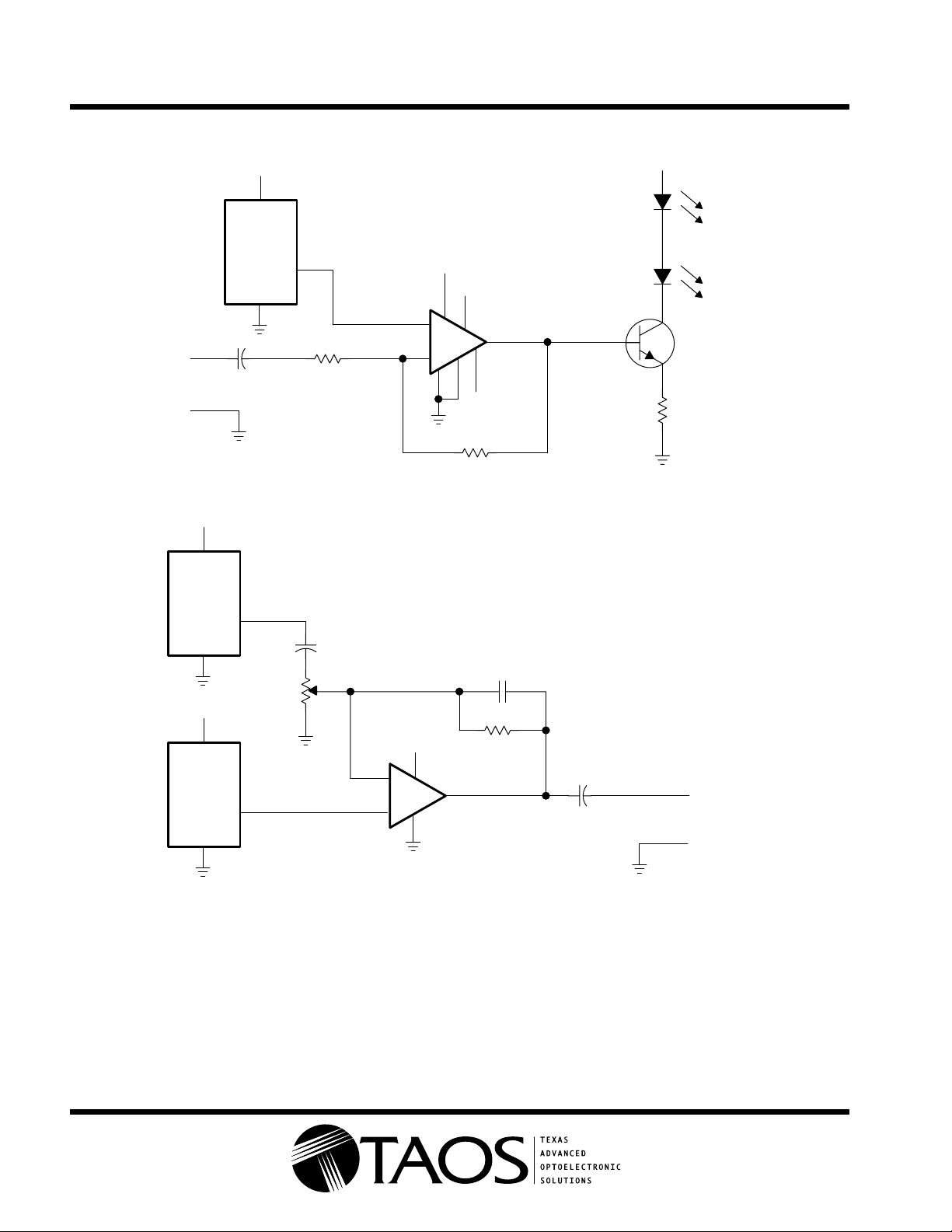
NOTE A: Simple transmission of audio signal over short distances (<10 ft). Applications include wireless headphones, wireless-telephone
headset, and wireless-headset intercom.
9 V
2
3
_
+
7
4
NE5534
RECEIVER
6
U3A
R1
100 kΩ
+
C2
47 µF
Output
(to headphones)
Figure 12. IR Voice-Band Audio Link
Copyright 2000, TAOS Inc.
8
www.taosinc.com
Page 9
TSL260, TSL261, TSL262
IR LIGHTTOVOLTAGE OPTICAL SENSORS
TAOS021 – MAY 2000
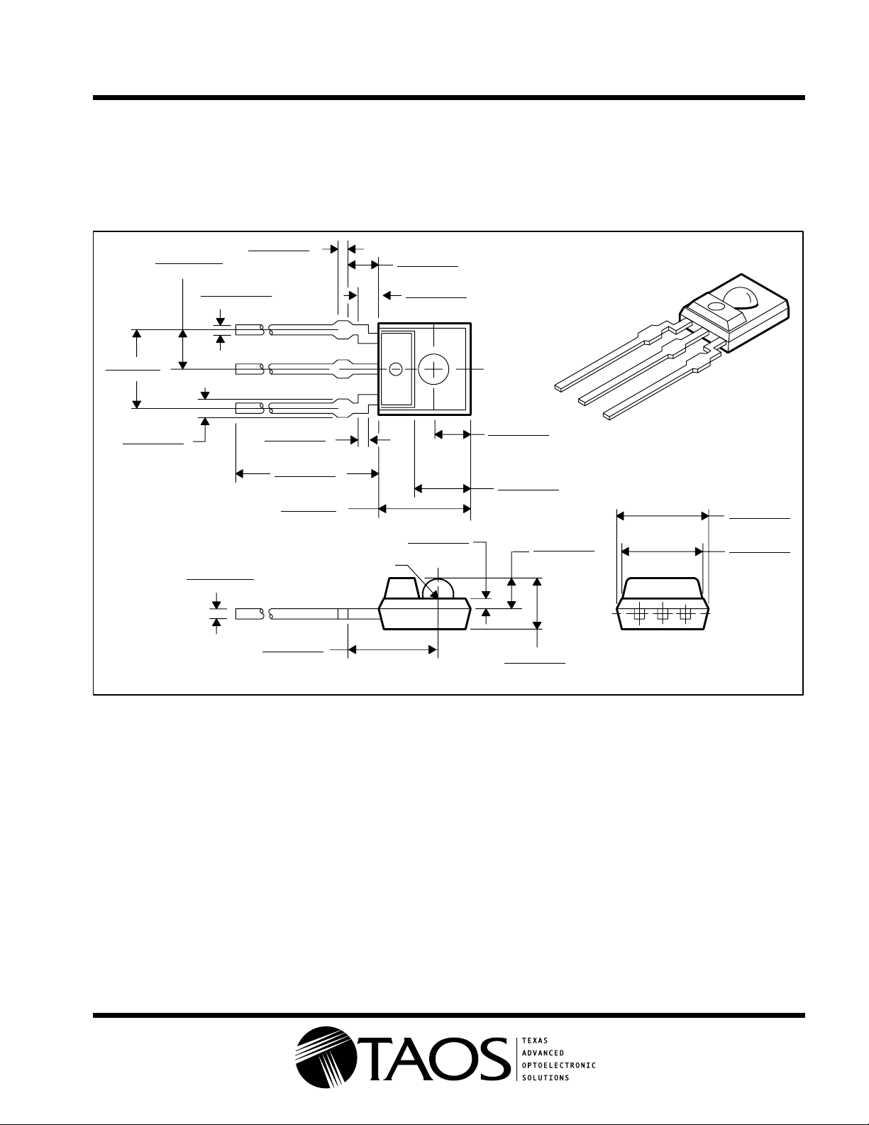
MECHANICAL DATA
The photodiode/amplifier chip is packaged in a black, infrared-transmissive plastic package. The integrated
photodiode active area is typically 1.0 mm2 (0.0016 in2), 0.5 mm2 (0.00078 in2), and 0.26 mm2 (0.0004 in2) for
the TSL260, TSL261, and TSL262, respectively.
4,2 (0.165)
3,8 (0.150)
0,86 (0.034)
0,46 (0.018)
2,125 (0.084)
1,875 (0.074)
0,635 (0.025)
0,4 (0.016)
0,51 (0.02)
0,385 (0.015)
0,75 (0.030)
0,65 (0.026)
1
2
3
0,65 (0.026)
0,55 (0.022)
15,7 (0.619)
13,2 (0.520)
4,8 (0.189)
4,4 (0.173)
0,75 (0.030) R
5,05 (0.199)
4,55 (0.179)
ALL LINEAR DIMENSIONS ARE IN MILLIMETERS AND PARENTHETICALLY IN INCHES
2,25 (0.089)
1,75 (0.069)
1,25 (0.049)
0,75 (0.029)
0,85 (0.033)
0,35 (0.014)
2,05 (0.081)
1,55 (0.061)
3,05 (0.120)
2,55 (0.100)
1,75 (0.069)
1,25 (0.049)
2,74 (0.108)
2,34 (0.092)
PIN 1 GND
PIN 2 V
PIN 3 OUT
1
2
DD
3
4,85 (0.191)
4,35 (0.171)
4,35 (0.171)
3,85 (0.152)
www.taosinc.com
Copyright 2000, TAOS Inc.
9
Page 10

TSL260, TSL261, TSL262
IR LIGHTTOVOLTAGE OPTICAL SENSORS
TAOS021 – MAY 2000
PRODUCTION DATA — information in this document is current at publication date. Products conform to
specifications in accordance with the terms of Texas Advanced Optoelectronic Solutions, Inc. standard
warranty. Production processing does not necessarily include testing of all parameters.
NOTICE
Texas Advanced Optoelectronic Solutions, Inc. (TAOS) reserves the right to make changes to the products contained in this
document to improve performance or for any other purpose, or to discontinue them without notice. Customers are advised
to contact TAOS to obtain the latest product information before placing orders or designing TAOS products into systems.
TAOS assumes no responsibility for the use of any products or circuits described in this document or customer product
design, conveys no license, either expressed or implied, under any patent or other right, and makes no representation that
the circuits are free of patent infringement. TAOS further makes no claim as to the suitability of its products for any particular
purpose, nor does TAOS assume any liability arising out of the use of any product or circuit, and specifically disclaims any
and all liability, including without limitation consequential or incidental damages.
TEXAS ADVANCED OPTOELECTRONIC SOLUTIONS, INC. PRODUCTS ARE NOT DESIGNED OR INTENDED FOR
USE IN CRITICAL APPLICATIONS IN WHICH THE FAILURE OR MALFUNCTION OF THE TAOS PRODUCT MAY
RESUL T I N PERSONAL INJURY OR DEATH. USE OF T AOS PRODUCTS IN LIFE SUPPOR T SYSTEMS IS EXPRESSLY
UNAUTHORIZED AND ANY SUCH USE BY A CUSTOMER IS COMPLETELY AT THE CUSTOMER’S RISK.
TAOS, the TAOS logo, and Texas Advanced Optoelectronic Solutions are trademarks of Texas Advanced Optoelectronic Solutions
Incorporated.
Copyright 2000, TAOS Inc.
10
www.taosinc.com
 Loading...