

Page 1
TSB12LV21B
(PCILynx-2) IEEE 1394 LINK LAYER CONTROLLER
SLLS306– JUL Y 1998
1
POST OFFICE BOX 655303 • DALLAS, TEXAS 75265
D IEEE Standard for a 1394-1995 Compliant
D IEEE Standard for a 1212-1991 Compliant
D Supports IEEE 1394-1995 Link Layer
Control
D PCI Local Bus Specification Rev. 2.1
Compliant
D Supports IEEE 1394 Transfer Rates of 100,
200, and 400 Mb per second
D 3.3-V Core Logic while Maintaining 5-V
Tolerant Inputs
D Performs the Function of 1394 Cycle
Master
D Provides 4K Bytes of Configurable FIFO
RAM
D Provides 5 Scatter-Gather DMA Channels
D Provides Software Control of Interrupt
Events
D Provides 4 General-Purpose Input/Outputs
D Supports Plug-and-Play (PnP) Specification
D Generates 32-bit CRC for Transmission of
1394 Packets
D Performs 32-bit CRC Checking on
Reception of 1394 Packets
D Provides PCI Bus Master Function for
Supporting DMA Operations
D Provides PCI Slave Function for Read/Write
Access of Internal Registers
D Supports Distributed DMA Transfers
Between 1394 and Local Bus RAM, ROM,
AUX, or Zoomed Video
D Advanced Submicron, Low-Power CMOS
T echnology
D Packaged in a 176-Pin PQFP (PGF)
Description 2. . . . . . . . . . . . . . . . . . . . . . . . . . . . . . . . . . . . . . . . . . . .
Terminal Assignment 3. . . . . . . . . . . . . . . . . . . . . . . . . . . . . . . . . . . .
Signal Name/Terminal Number Sort Tables 4. . . . . . . . . . . . . . . . .
Terminal Functions 5. . . . . . . . . . . . . . . . . . . . . . . . . . . . . . . . . . . . .
System Block Diagram 9. . . . . . . . . . . . . . . . . . . . . . . . . . . . . . . . . .
Functional Block Diagram 10. . . . . . . . . . . . . . . . . . . . . . . . . . . . . .
Absolute Maximum Ratings 11. . . . . . . . . . . . . . . . . . . . . . . . . . . . . . . .
Recommended Operating Conditions 11. . . . . . . . . . . . . . . . . . . . . . .
Electrical Characteristics 12. . . . . . . . . . . . . . . . . . . . . . . . . . . . . . . . . .
PCI Interface Switching Characteristics 13. . . . . . . . . . . . . . . . . . . . . .
Parameter Measurement Information 15. . . . . . . . . . . . . . . . . . . . . . . .
Power Supply Sequencing 20. . . . . . . . . . . . . . . . . . . . . . . . . . . . . . . . .
Mechanical Data 21. . . . . . . . . . . . . . . . . . . . . . . . . . . . . . . . . . . . . . . . .
Table of Contents
Copyright 1998, Texas Instruments Incorporated
PRODUCTION DATA information is current as of publication date.
Products conform to specifications per the terms of Texas Instruments
standard warranty. Production processing does not necessarily include
testing of all parameters.
Please be aware that an important notice concerning availability, standard warranty, and use in critical applications of
Texas Instruments semiconductor products and disclaimers thereto appears at the end of this data sheet.
Page 2

TSB12LV21B
(PCILynx-2) IEEE 1394 LINK LAYER CONTROLLER
SLLS306– JUL Y 1998
2
POST OFFICE BOX 655303 • DALLAS, TEXAS 75265
description
The TSB12LV21B (PCILynx-2) provides a high-performance IEEE 1394-1995 interface with the capability to
transfer data between the 1394 PHY-link interface, the PCI bus interface, and external devices connected to
the local bus interface. The 1394 PHY -link interface provides the connection to the 1394 physical layer device;
it is supported by the on-board link layer controller (LLC). The LLC provides the control for transmitting and
receiving 1394 packet data between the FIFO and PHY -link interface at rates of 100 Mbit/s, 200 Mbit/s, and 400
Mbit/s. The link layer also provides the capability to receive status from the physical layer device and to access
the physical layer control and status registers by the application software. The PCILynx–2 complies with
D PCI Local Bus Specification, Revision 2.1
D IEEE Standard for a 1394-1995 High Performance Serial Bus
D IEEE Standard 1212-1991
D IEEE Standard Control and Status Register (CSR) Architecture for Microcomputer Buses
An internal 4Kbyte-memory can be configured as multiple variable-size FIFOs, eliminating the need for external
FIFOs. Separate FIFOs are user configurable to support 1394 receive, asynchronous transmit, and
isynchronous transmit transfer operations.
The PCI interface supports 32-bit burst transfers up to 33 MHz and is capable of operating both as a master
and as a target device. Configuration registers can be loaded from an external serial EEPROM, allowing board
and system designers to assign their own unique identification codes. An autoboot mode allows data-moving
systems (such as docking stations) to be designed to operate on the PCI bus without the need for a host CPU.
The DMA controller uses packet control list (PCL) data structures to control the transfer of data and allow the
DMA to operate without host CPU intervention. These PCLs can reside in PCI memory or in memory that is
connected to a local bus port. The PCLs implement an instruction set that allows linking, conditional branching,
1394 data transfer control, auxiliary support commands, and status reporting. Five DMA channels
accommodate programmable data types. PCLs can be chained together to form a channel control program that
can be developed to support each DMA channel. Data can be stored in either big endian or little endian format,
eliminating the need for the host CPU to perform byte swapping. Data can be transferred either to 4-byte aligned
locations, to provide the highest performance, or to nonaligned locations, to provide the best memory use.
The RAM, ROM, AUX, ZV , and general purpose I/O (GPIO) ports collectively make up the local bus interface.
These ports mapped into the PCI address, can be accessed either through the PCI bus or through internal DMA
transactions. Internal transactions do not appear on the external PCI bus, thereby conserving PCI bandwidth.
DMA packet control lists or other data may be stored in external RAM or ROM attached to the local bus interface.
This further reduces PCI bus use and generally improves performance. The ZV local bus port is designed to
transfer data from 1394 video devices to an external device connected to the PCILynx-2 ZV port. This interface
provides a method for receiving 1394 digital camera packets directly from a ZV-compliant device attached to
the local bus interface.
Built-in test registers, a dedicated test output terminal, and four GPIO terminals allow observation of internal
states and provide a convenient software debug capability. Programmable interrupts are available to inform
driver software of important events, such as 1394 bus resets and DMA-to-PCL transfer completion.
The 3.3-V internal operation provides reduced power consumption, while maintaining compatibility with 5-V
signaling environments. The PCI interface is compatible with both 3-V and 5-V PCI systems.
Page 3
TSB12LV21B
(PCILynx-2) IEEE 1394 LINK LAYER CONTROLLER
SLLS306– JUL Y 1998
3
POST OFFICE BOX 655303 • DALLAS, TEXAS 75265
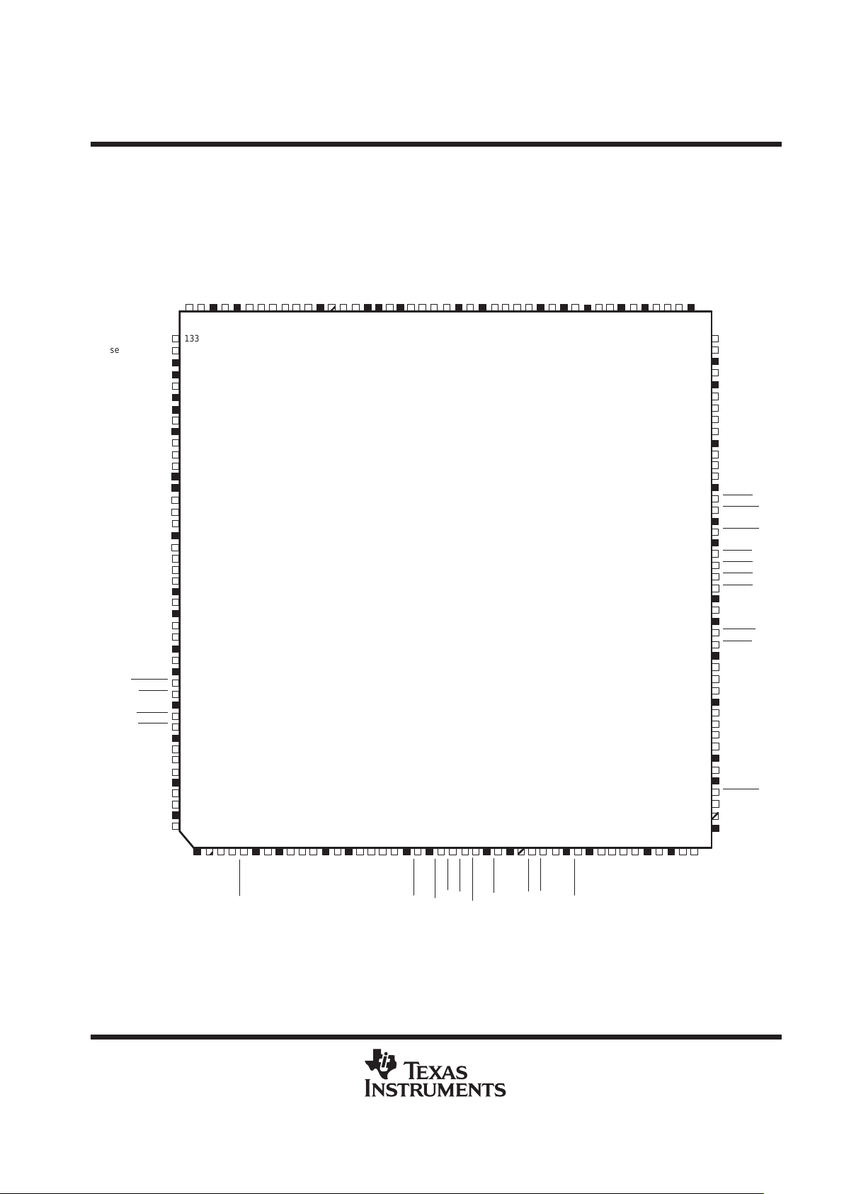
terminal assignment
PGF QUAD FLATPACK PACKAGE
TOP VIEW
seeprom_clk
50
75
aux_data15
phy_data0
pci_ad29
TSB12LV21B
133
seeprom_data 134
5V V
CC
135
3V V
CC
136
link_cyclein 137
3.3V V
CC
138
link_cycleout
139
test_out 140
GND 141
phy_ctl0 142
phy_ctl1
143
phy_lreq
144
3.3V V
CC
145
146
phy_data1
147
phy_data2 148
phy_data3 149
GND 150
phy_data4
151
phy_data5
152
phy_data6 153
phy_data7 154
GND 155
phy_clk50 156
3.3V V
CC
157
GND/test_enable 158
autoboot 159
GND 160
pci_clk
161
5V V
CC
162
pci_reset
163
pci_gnt
164
3.3V V
CC
165
pci_inta
166
pci_req
167
GND
168
pci_ad31 169
pci_ad30
170
171171
3.3V V
CC
172
pci_ad28
173
pci_ad27 174
GND
175
pci_ad26 176
3.3V V
CC
pci_ad7
aux_data6
aux_data787
3.3V V
CC
86
au_data885
5VV
CC
84
aux_data983
aux_data1082
aux_data1181
aux_data1280
GND79
aux_data1378
aux_data1477
76
aux_oe
74
aux_we0
73
GND72
aux_we1
71
3.3V V
CC
70
aux_cs
69
rom_cs
68
ram_cs67
aux_rst
66
GND65
aux_clk64
5V V
CC
63
aux_rdy
62
aux_int
61
5V V
CC
60
pci_ad059
pci_ad158
pci_ad257
3.3V V
CC
56
pci_ad355
pci_ad454
pci_ad5
pci_ad652
GND51
3.3V V
CC
49
pci_cbe0
48
pci_ad847
NC46
GND45
53
89
zv_data_valid
zv_hsync
GND
zv_ext_clk
3.3V VCCzv_vsync
zv_pix_clk
gpio_data0
gpio_data1
gpio_data2
gpio_data3
GND
132
131
130
129
128
127
126
125
124
123
122
121
120
119
118
117
116
115
114
113
112
111
110
aux_adr0NCaux_adr1
aux_adr2
3.3V VCCaux_adr3
GND
aux_adr4
aux_adr5
aux_adr6
aux_adr7
5V VCCaux_adr8
3.3V VCCaux_adr9
aux_adr10
109
108
107
106
105
104
103
102
101
100
9998979695949392919089
aux_adr11
aux_adr12
GND
aux_adr13
3.3V VCCaux_adr14
aux_adr15
aux_data0
aux_data1
GND
aux_data2
3.3V VCCaux_data3
aux_data4
aux_data5
GND
12345678910111213141516171819202122232425262728293031323334353637383940414243
44
3.3V V
CC
NC
pci_ad25
pci_ad24
pci_cbe3
GND
pci_idsel
3.3V V
CC
pci_ad23
pci_ad22
pci_ad21
5V V
CC
pci_ad20
GND
pci_ad19
pci_ad18
pci_ad17
pci_ad16
3.3V V
CC
GND
pci_frame
pci_irdy
pci_trdy
pci_devsel
pci_stop
3.3V V
CC
GND
NC
pci_cbe2
pci_perr
pci_serr
pci_par
3.3V V
CC
pci_cbe1
GND
pci_ad15
pci_ad14
pci_ad13
pci_ad12
5V V
CC
pci_ad11
3.3V V
CC
pci_ad10
pci_ad9
Figure 1. PCILynx-2 Terminal Assignment/Pinout
Page 4
TSB12LV21B
(PCILynx-2) IEEE 1394 LINK LAYER CONTROLLER
SLLS306– JUL Y 1998
4
POST OFFICE BOX 655303 • DALLAS, TEXAS 75265
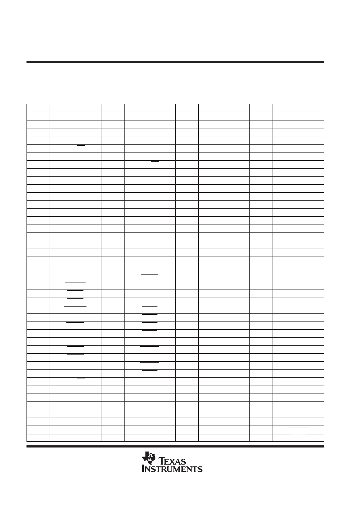
pin description table
This sections identifies and classifies the functionality of each pin on the PCILynx–2.
Table 1. Signals Sorted by Pin Number
PIN NO. SIGNAL NAME PIN NO. SIGNAL NAME PIN NO. SIGNAL NAME PIN NO. SIGNAL NAME
1 3.3V V
CC
42 3.3V V
CC
83 aux_data9 124 gpio_data1
2 NC 43 pci_ad10 84 5.0VV
CC
125 gpio_data0
3 pci_ad25 44 pci_ad9 85 aux_data8 126 zp_pix_clk
4 pci_ad24 45 GND 86 3.3V V
CC
127 zv_vsync
5 pci_cbe3 46 NC 87 aux_data7 128 3.3V V
CC
6 GND 47 pci_ad8 88 aux_data6 129 zv_ext_clk
7 pci_idsel 48 pci_cbe0 89 GND 130 GND
8 3.3V V
CC
49 3.3V V
CC
90 aux_data5 131 zv_hsync
9 pci_ad23 50 pci_ad7 91 aux_data4 132 zv_data_valid
10 pci_ad22 51 GND 92 aux_data3 133 seeprom_clk
11 pci_ad21 52 pci_ad6 93 3.3V V
CC
134 seeprom_data
12 5.0V V
CC
53 pci_ad5 94 aux_data2 135 5V V
CC
13 pci_ad20 54 pci_ad4 95 GND 136 3V V
CC
14 GND 55 pci_ad3 96 aux_data1 137 link_cyclein
15 pci_ad19 56 3.3V V
CC
97 aux_data0 138 3.3VV
CC
16 pci_ad18 57 pci_ad2 98 aux_adr15 139 link_cylceout
17 pci_ad17 58 pci_ad1 99 aux_adr14 140 test_out
18 pci_ad16 59 pci_ad0 100 3.3V V
CC
141 GND
19 3.3V V
CC
60 5.0V V
CC
101 aux_adr13 142 phy_ctl0
20 pci_cbe2 61 aux_int 102 GND 143 phy_ctl1
21 GND 62 aux_rdy 103 aux_adr12 144 phy_lreq
22 pci_frame 63 5.0V V
CC
104 aux_adr11 145 3.3V V
CC
23 pci_irdy 64 aux_clk 105 aux_adr10 146 phy_data0
24 pci_trdy 65 GND 106 aux_adr9 147 phy_data1
25 pci_devsel 66 aux_rst 107 3.3V V
CC
148 phy_data2
26 3.3V V
CC
67 ram_cs 108 aux_adr8 149 phy_data3
27 pci_stop 68 rom_cs 109 5.0V V
CC
150 GND
28 GND 69 aux_cs 110 aux_adr7 151 phy_data4
29 NC 70 3.3V V
CC
111 aux_adr6 152 phy_data5
30 pci_perr 71 aux_we1 112 aux_adr5 153 phy_data6
31 pci_serr 72 GND 113 aux_adr4 154 phy_data7
32 pci_par 73 aux_we0 114 GND 155 GND
33 3.3V V
CC
74 aux_oe 115 aux_adr3 156 phy_clk50
34 pci_cbe1 75 3.3V V
CC
116 3.3V V
CC
157 3.3V V
CC
35 GND 76 aux_data15 117 aux_adr2 158 test_out/GND
36 pci_ad15 77 aux_data14 118 aux_adr1 159 auto_boot
37 pci_ad14 78 aux_data13 119 aux_adr0 160 GND
38 pci_ad13 79 GND 120 NC 161 pci_clk
39 pci_ad12 80 aux_data12 121 GND 162 5.0V V
CC
40 5.0V V
CC
81 aux_data11 122 gpio_data3 163 pci_reset
41 pci_ad11 82 aux_data10 123 gpio_data2 164 pci_gnt
Page 5
TSB12LV21B
(PCILynx-2) IEEE 1394 LINK LAYER CONTROLLER
SLLS306– JUL Y 1998
5
POST OFFICE BOX 655303 • DALLAS, TEXAS 75265
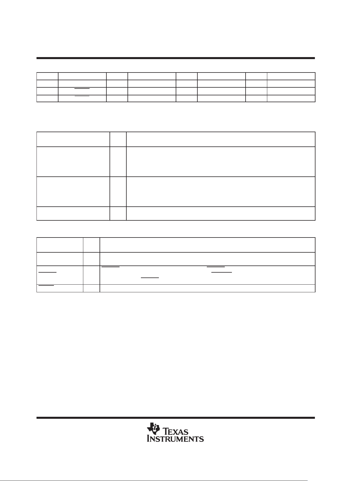
Table 1. Signals Sorted by Pin Number (Continued)
PIN NO. SIGNAL NAME PIN NO. SIGNAL NAME PIN NO. SIGNAL NAME PIN NO. SIGNAL NAME
165 3.3V V
CC
168 GND 171 pci_ad29 174 pci_ad27
166 pci_inta 169 pci_ad31 172 3.3V V
CC
175 GND
167 pci_req 170 pci_ad30 173 pci_ad28 176 pci_ad26
Terminal Functions
power supply terminals
TERMINAL
I/O
NAME NO.
I/O
TYPE
FUNCTION
GND
6, 14, 21, 28, 35, 45,
51, 65, 72, 79, 89,
95, 102, 114, 121,
130, 141, 150, 155,
160, 168, 175
I Device ground terminals
3.3V VCC
1, 8, 19, 26, 33, 42,
49, 56, 70, 75, 86,
93, 100, 107, 116,
128, 136, 138, 145,
157, 165, 172
I 3.3-V power supply terminal for core logic
5.0V VCC
12, 40, 60, 63, 84,
109, 162
I 5-V power rail for 5-V tolerant Input buffers
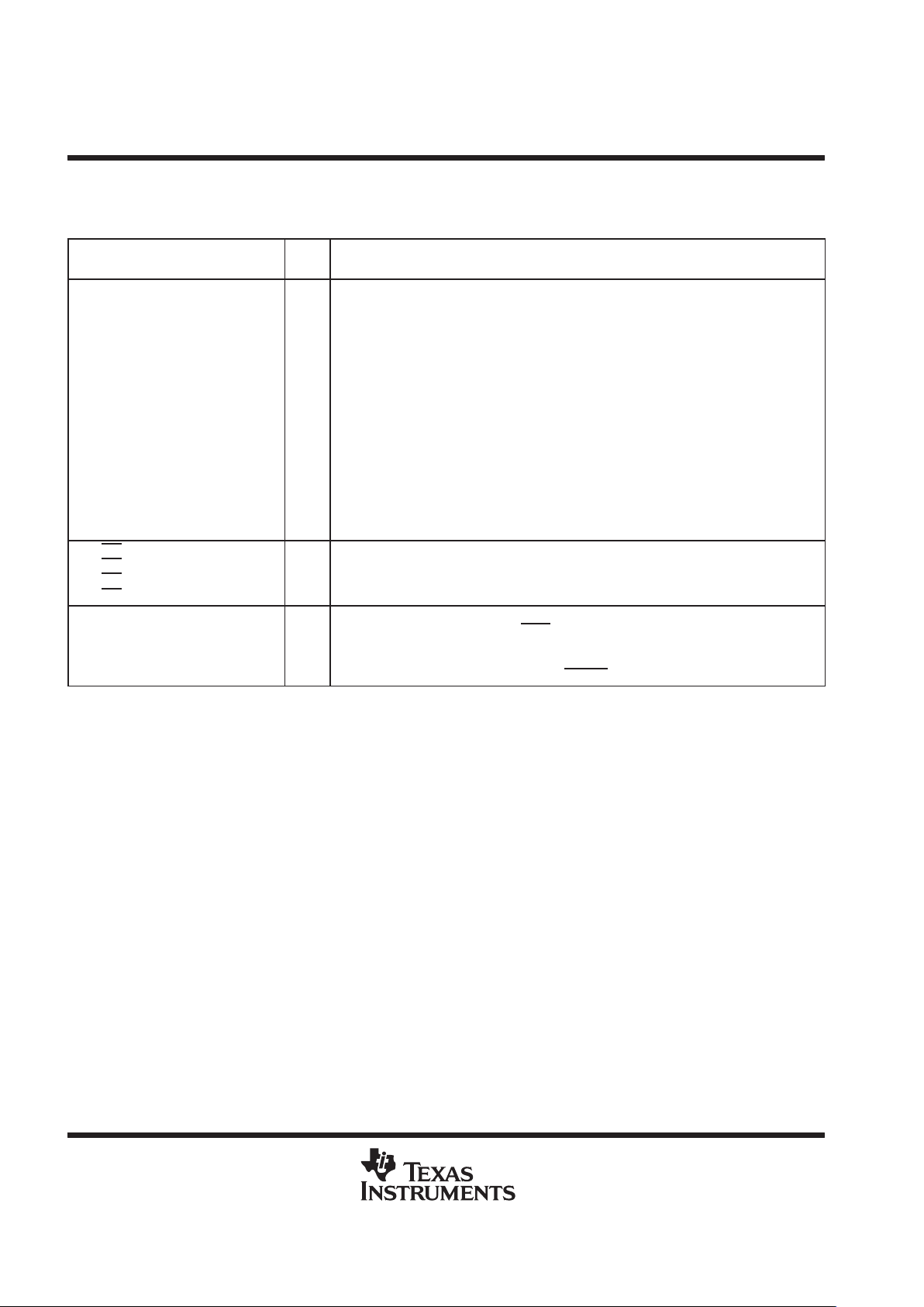
PCI system terminals
TERMINAL
I/O
NAME NO.
I/O
TYPE
FUNCTION
pci_clk 161 I
System PCI bus clock. This signal ranges from 0MHz–-33MHz MHz and provides timing for all transactions
on the PCI bus. All PCI signals are sampled at the rising edge of PCLK.
pci_reset 163 I
pci_reset. When the PCI bus reset is asserted the pci_reset signal causes the PCILynx-2 to 3-state all
output buffers and reset all internal registers. When pci_reset
is asserted, the device is completely
nonfunctional. After pci_reset
is deasserted, the PCILynx-2 is in its default state.
pci_inta 166 OD PCI system interrupt A. This is an open drain signal.
Page 6
TSB12LV21B
(PCILynx-2) IEEE 1394 LINK LAYER CONTROLLER
SLLS306– JUL Y 1998
6
POST OFFICE BOX 655303 • DALLAS, TEXAS 75265
Terminal Functions (Continued)
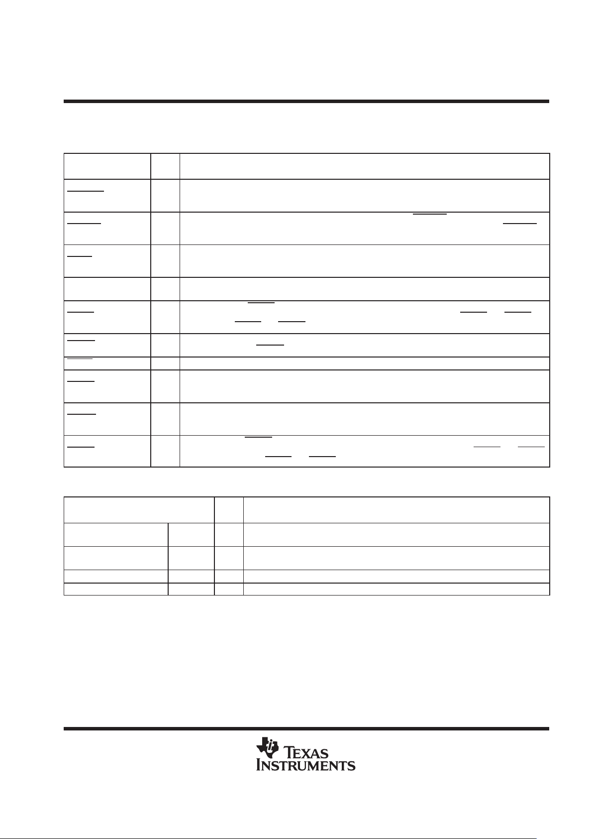
PCI address and data terminals
TERMINAL
I/O
NAME NO.
I/O
TYPE
FUNCTION
pci_ad31 – pci_ad29
pci_ad28
pci_ad27
pci_ad26
pci_ad25
pci_ad24
pci_ad23 – pci_ad21
pci_ad20
pci_ad19 – pci_ad16
pci_ad15 – pci_ad12
pci_ad1 1
pci_ad10
pci_ad9
pci_ad8
pci_ad7
pci_ad6 – pci_ad3
pci_ad2 – pci_ad0
169 – 171
173
174
176
3
4
9 – 11
13
15 – 18
36 – 39
41
43
44
47
50
52 – 55
57 – 59
I/O
Multiplexed PCI address and data signals. During the address phase of a primary bus PCI
cycle, pci_ad31:0 contain a 32-bit address or other destination information. During the data
phase pci_ad31:0 contain data
pci_cbe3
pci_cbe2
pci_cbe1
pci_cbe0
5
20
34
48
I/O PCI Command/Byte enables
pci_par 32 I/O
PCI bus parity. In all PCI bus read and write cycles the PCILynx–2 calculates even paritacross the pci_ad31:0 and pci_cbe3:0
signals. As an initiator during PCI cycles, the
PCILynx-2 outputs this parity indicator with a one pci_clk delay. As a target during PCI
cycles, the calculated parity is compared to the initiator’s parity indicator. A miscompare
can result in the assertion of a parity error (pci_perr
).
Page 7
TSB12LV21B
(PCILynx-2) IEEE 1394 LINK LAYER CONTROLLER
SLLS306– JUL Y 1998
7
POST OFFICE BOX 655303 • DALLAS, TEXAS 75265
Terminal Functions (Continued)
PCI interface control
TERMINAL
I/O
NAME NO.
I/O
TYPE
FUNCTION
pci_devsel 24 I/O
PCI device select. The PCILynx-2 asserts this signal to claim a PCI cycle as the target device. As a PCI
initiator on the bus, the PCILynx-2 monitors this signal until a target responds. If no target responds before
time-out occurs, then the PCILynx-2 will terminate the cycle with an initiator abort.
pci_frame 22 I/O
PCI cycle frame. This signal is driven by the initiator of a bus cycle. pci_frame is asserted to indicate that a
bus transaction is beginning, and data transfers continue while this signal is asserted. When pci_frame
is
deasserted the PCI bus transaction is in the final data phase.
pci_gnt 164 I
PCI bus grant. This signal is driven by the PCI bus arbiter to grant the PCILynx-2 access to the PCI bus
after the current data transaction has completed. This signal may or may not follow a PCI bus request
depending upon the PCI bus parking algorithm.
pci_idsel 7 I
Initialization device select. pci_idsel selects the PCILynx-2 during configuration space accesses. pci_idsel
can be connected to one of the upper 24 PCI address lines on the PCI bus.
pci_irdy 23 I/O
PCI initiator ready. pci_irdy indicates the PCI bus initiator’s ability to complete the current data phase of the
transaction. A data phase is completed upon a rising edge of pci_clk where both pci_irdy
and pci_trdy are
asserted. Until pci_irdy
and pci_trdy are both sampled asserted, wait states are inserted.
pci_perr 30 I/O
PCI parity error indicator. This signal is driven by a PCI device to indicate that calculated parity does not
match pci_par, when pci_perr
is enabled through bit 6 of the command register.
pci_req 167 O PCI bus request. Asserted by the PCIL ynx-2 to request access to the PCI bus as an initiator.
pci_serr 31 OD
PCI system error. Output that is pulsed from the PCILynx-2 when enabled through the command register,
indicating a system error has occurred. The PCILynx-2 needs not be the target of the PCI cycle in order to
assert this signal.
pci_stop 27 I/O
PCI cycle stop signal. This signal is driven by a PCI target to request the initiator to stop the current PCI
bus transaction. This signal is used for target disconnects and is commonly asserted by target devices
which do not support burst data transfers.
pci_trdy 24 I/O
PCI target ready. pci_trdy indicates the primary bus target’s ability to complete the current data phase of
the transaction. A data phase is completed upon a rising edge of pci_clk where both pci_irdy
and pci_trdy
are asserted. Until both pci_irdy and pci_trdy are asserted, wait states are inserted.
IEEE 1394 PHY/LINK interface terminals
TERMINAL
I/O
NAME NO.
I/O
TYPE
FUNCTION
phy_ctl1
phy_ctl0
143
142
I/O PHY -link bidirectional control lines
phy_data7 – phy_data4
phy_data3 – phy_data0
154 – 151
149 – 146
I/O PHY -link bidirectional data lines
phy_clk50 156 I 50MHz-System clock from PHY chip
phy_lreq 144 O PHY -link request signal generated by the PCILynx-2 controller
Page 8

TSB12LV21B
(PCILynx-2) IEEE 1394 LINK LAYER CONTROLLER
SLLS306– JUL Y 1998
8
POST OFFICE BOX 655303 • DALLAS, TEXAS 75265
Terminal Functions (Continued)
auxiliary/zoom video port terminals
TERMINAL
I/O
NAME NO.
I/O
TYPE
FUNCTION
aux_clk 64 O Auxiliary port clock out. This signal is output at the frequency of the PCI clock.
aux_rst 66 O Auxiliary port reset out
aux_int 61 I Auxiliary port interrupt input
aux_adr15 – aux_adr14
aux_adr13
aux_adr12 –aux_adr9
aux_adr8
aux_adr7 –aux_adr4
aux_adr3
aux_adr2 – aux_adr0
98 – 99
101
103 – 106
108
110 – 113
115
117 – 119
O Auxiliary port address lines output to external logic
aux_data15 – aux_data13
aux_data12 – aux_data9
aux_data8
aux_data7 – aux_data6
aux_data5 – aux_data3
aux_data2
aux_data1 – aux_data0
76 – 78
80 – 83
85
87 – 88
90 – 92
94
96 – 97
I/O Auxiliary port bidirectional data bus to external logic
aux_cs 69 O Auxiliary port chip select to external logic
aux_oe 74 O Auxiliary port output enable to enable external logic data onto the auxiliary data bus
aux_rdy 62 I Auxiliary port ready indication from external logic
aux_we1
aux_we0
71
73
O Auxiliary port write strobes to external logic
ram_cs 67 O External RAM chip select
rom_cs 68 O External ROM chip select
zv_data_valid 132 O Zoom video port data valid signal
zv_ext_clk 129 I Zoom video port external clock input
zv_hsync 131 O Zoom video port horizontal sync signal
zv_pix_clk 126 I/O Zoom video port pixel clock for zoomed video data
zv_vsync 127 O Zoom video port vertical sync signal
miscellaneous
TERMINAL
I/O
NAME NO.
I/O
TYPE
FUNCTION
autoboot 159 I
Autoboot. Selects autoboot mode. When this terminal is tied high, autoboot mode is
selected.
gpio_data3 – gpio_data2 122 – 125 I/O Auxiliary port general-purpose programmable I/O signals
link_cyclein 137 I Optional 8kHz clock for use as the cycle clock
link_cycleout 140 O Cycle timer 8kHz clock output
seeprom_clk 133 I/O External serial EEPROM data clock
seeprom_data 134 I/O External serial EEPROM read/write data line
test_enable/GND 158 I
Enables TEST_OUT for AND tree testing. This pin should be tied to GND if AND tree
testing is not used.
test_out 140 O Output for AND tree testing
Page 9

TSB12LV21B
(PCILynx-2) IEEE 1394 LINK LAYER CONTROLLER
SLLS306– JUL Y 1998
9
POST OFFICE BOX 655303 • DALLAS, TEXAS 75265
system block diagram
The following figure illustrates a typical system implementation of the PCILynx-2.
PCILynx-2
TSB12LV21B
PCI Bus
Local Bus
PCI
Expansion
ROM
Video
Controller
PCI
Host
Bridge
Local
Memory
Host
CPU
DMA
Channel
Control
(SRAM)
User
Defined
Function
(AUX)
ZV
Port
(Video)
1394
Desktop
Camera
1394
CD ROM
1394
Laser
Printer
1394
Digital
VCR
1394
Video Cable
Set Top Box
1394 Peripheral Devices
Personal Computer
IDE
Controller
1394
3 Port
Physical
Layer
Figure 2. System Block Diagram
Page 10

TSB12LV21B
(PCILynx-2) IEEE 1394 LINK LAYER CONTROLLER
SLLS306– JUL Y 1998
10
POST OFFICE BOX 655303 • DALLAS, TEXAS 75265
functional block diagram
Serial EPROM
Interface
PCI Master
PCI Slave
Local Bus
Interface
Logic
PCI Configuration Control
and Status Registers
RAM
ROM
AUX
ZV
seeprom_data
seeprom_clk
pci_ad31 – pci_ad0
pci_cbe3
– pci_cbe0
pci_par
pci_frame
pci_irdy
pci_trdy
pci_devsel
pci_stop
pci_idsel
pci_perr
pci_serr
pci_req
pci_gnt
pci_clk
pci_reset
pci_inta
32
/
4
/
PCI Bus Logic
4
/
16
/
16
/
2
/
3
/
3
/
aux_clk
aux_rst
gpio_data3 – gpio_data0
aux_adr15 – aux_adr0
aux_data15 – aux_data0
aux_oe
aux_we1 – aux_we0
aux_rdy
zv_hsync, zv_vsync, zv_pix_clk
aux_cs
, rom_cs, ram_cs
aux_int
zv_data_valid
DMA Engine
DMA Control
and
Status Registers
DMA Logic
General
Receiver
FIFO
Asynchronous
Transmit
FIFO
Isosynchronous
Transmit
FIFO
FIFO Control
and Status
Registers
Pointer
Address
Mapping Logic
FIFO Logic
2
/
8
/
phy_ctl0 – phy_ctl1
phy_data0 – phy_data7
phy_clk50
link_cyclein
phy_lreq
link_cycleout
1394 LLC
Control and
Status Registers
Cycle
Timer
Cycle
Monitor
1394 Packet
Transmit
Control Logic
CRC Logic
1394 Packet
Receive
Control Logic
Phy-Link
Interface
Logic
Parallel-to-Serial
Serial-to-Parallel
1394 Link Layer Control (LLC) Logic
zv_ext_clk
Figure 3. Functional Block Diagram
Page 11

TSB12LV21B
(PCILynx-2) IEEE 1394 LINK LAYER CONTROLLER
SLLS306– JUL Y 1998
11
POST OFFICE BOX 655303 • DALLAS, TEXAS 75265
absolute maximum ratings over operating temperature ranges (unless otherwise noted)
†
Supply voltage range,VCC –0.5 V to 4 V. . . . . . . . . . . . . . . . . . . . . . . . . . . . . . . . . . . . . . . . . . . . . . . . . . . . . . . . . .
V
CCP
–0.5 V to 6 V. . . . . . . . . . . . . . . . . . . . . . . . . . . . . . . . . . . . . . . . . . . . . . . . . . . . . . . . .
V
CC5V
–0.5 V to 6 V. . . . . . . . . . . . . . . . . . . . . . . . . . . . . . . . . . . . . . . . . . . . . . . . . . . . . . . .
Input voltage range for Universal PCI, VI: PCI –0.5 V to V
CCP
+ 0.5 V. . . . . . . . . . . . . . . . . . . . . . . . . . . . . . . .
Input voltage range for 5-V tolerant TTL/LVCMOS, VI: –0.5 V to V
CC5V
+ 0.5 V. . . . . . . . . . . . . . . . . . . . . . . .
Output voltage range for Universal PCI, VO –0.5 V to V
CCP
+ 0.5 V. . . . . . . . . . . . . . . . . . . . . . . . . . . . . . . . . .
Output voltage range for 5-V tolerant TTL/LVCMOS, VO –0.5 V to V
CC5V
+ 0.5 V. . . . . . . . . . . . . . . . . . . . . .
Input clamp current, I
IK
(VI < 0 or VI > VCC) (see Note 2) ± 20 mA. . . . . . . . . . . . . . . . . . . . . . . . . . . . . . . . . . . .
Output clamp current, IOK (VO < 0 or VO > VCC) (see Note 3) ± 20 mA. . . . . . . . . . . . . . . . . . . . . . . . . . . . . . . .
†
Stresses beyond those listed under “absolute maximum ratings” may cause permanent damage to the device. These are stress ratings only, and
functional operation of the device at these or any other conditions beyond those indicated under “recommended operating conditions” is not
implied. Exposure to absolute-maximum-rated conditions for extended periods may affect device reliability.
NOTES: 1. Applies to external input and bidirectional buffers. For 5-V tolerant buffers, use VI > V
CC5V
. For Universal PCI, use VI > V
CCP.
2. Applies to external output and bidirectional buffers. For 5-V tolerant buffers, use VO > V
CC5V .
For Universal PCI, use VO > V
CCP .
recommended operating conditions (see Note 3)
OPERATION MIN NOM MAX UNIT
Core voltage, V
CC
Commercial 3.3 3 3.3 3.6 V
I/O voltage, V
CCP
Commercial 5 3 5 5.5 V
I/O voltage, V
CC5V
Commercial 5 3 5 5.5 V
High-level Input voltage, V
IH
†
2
V
Low-level Input voltage, V
IL
†
0.8 V
Universal PCI 0 V
CCP
Input voltage, V
I
5-V tolerant
0 V
CC5V
V
Output voltage, V
O
‡
0 V
CC
V
Input transition times (tr and tf), t
t
0 6 ns
Operating ambient temperature range, T
A
0 25 70 °C
Virtual junction temperature, T
J
§
0 25 115 °C
†
Applies for external input and bidirectional buffers without hysteresis.
‡
Applies for external output buffers.
§
These junction temperatures reflect simulation conditions. Customer is responsible for verifying junction temperature.
NOTE 3: Unused or floating pins (input or I/O) must be held high or low.
Page 12

TSB12LV21B
(PCILynx-2) IEEE 1394 LINK LAYER CONTROLLER
SLLS306– JUL Y 1998
12
POST OFFICE BOX 655303 • DALLAS, TEXAS 75265
electrical characteristics over recommended operating conditions (unless otherwise noted)
PARAMETER OPERATION
TEST
CONDITIONS
MIN MAX UNIT
3.3 V IOH = –0.5 mA 0.9 V
CC
High-level output voltage
PCI
5 V
IOH = –2 mA 2.4
V
OH
High level out ut voltage
(see Note 4)
TTL/LVCMOS
†
IOH = –18 mA 2.4
V
TTL/LVCMOS
‡
IOH = –14 mA 2.4
3.3 V IOL = 1.5 mA 0.1 V
CC
PCI
5 V IOL = 6 mA 0.5
V
OL
Low-level output voltage
TTL/LVCMOS
†
IOL = 18 mA 0.5
V
TTL/LVCMOS
‡
IOL = 14 mA 0.5
Bushold VI = 0.8 V 20
Input pins
Others VI = GND –1
I
IL
Low-level input current
Bushold VI = 0.8 V 400
µA
I/O pins
Others VI = GND –20
Bushold VI = 2 V –20
Input pins
Others VI = 5.5 V 20
I
IH
High-level input current
Bushold VI = 2 V –20
µA
I/O pins
Others VI = 5.5 V 20
†
All PHY -link pins, aux_clk(64), aux_we1(71), and aux_we0(73).
‡
All other TTL/LVCMOS pins
NOTE 4: VOH is not tested on pci_serr
(31) or pci_inta(166) due to open-drain output.
Page 13

TSB12LV21B
(PCILynx-2) IEEE 1394 LINK LAYER CONTROLLER
SLLS306– JUL Y 1998
13
POST OFFICE BOX 655303 • DALLAS, TEXAS 75265
PCI interface switching characteristics, see Figure 4
PARAMETER
MEASURED
TEST
CONDITION
MIN
TYP
MAX
UNIT
t
su1
Setup time, pci_xx low or high to pci_clk high
†
40% to 40%
7
ns
t
h1
ББББББББББББББ
Á
Hold time, pci_clk high to pci_xx low or high†, pci_gnt low or
high
ÁÁÁ
Á
40% to 40%
ÁÁÁÁÁ
Á
0
ÁÁÁÁÁ
Á
ns
t
d1
Delay time, pci_clk high to pci_xx low or high
†
40% to 40%
2
11
ns
t
su2
Setup time, pci_gnt low or high to pci_clk high
40% to 40%
10
ns
t
d2
Delay time, pci_clk high to pci_inta low or high
40% to 40%
2
13
ns
†
In this case, pci_xx refers to the following signals; pci_ad31–0, pci_cbe3–0
, pci_par, pci_frame, pci_irdy , pci_trdy, pci_devsel, pci_stop, pci_idsel,
pci_perr
, pci_serr, pci_req.
phy-link interface switching characteristics, see Figure 5
БББББББББББББББ
Á
PARAMETER
ÁÁÁ
Á
MEASURED
ÁÁÁ
Á
TEST
CONDITION
Á
Á
MIN
Á
Á
TYP
Á
Á
MAX
Á
Á
UNIT
t
su3
БББББББББББББББ
Setup time, phy_xx low or high to phy_clk high
†
1.3 V to 1.3 V
4
ns
t
h2
БББББББББББББББ
Hold time, phy_clk high to phy_xx, link_cyclein low or high
1.3 V to 1.3 V
1
ns
t
d3
БББББББББББББББ
Delay time, phy_clk high to phy_xx, phy_lreq low or high
†
1.3 V to 1.3 V
3
11
ns
t
su4
БББББББББББББББ
Setup time, phy_clk high to link_cyclein low or high
1.3 V to 1.3 V
5
ns
t
d4
БББББББББББББББ
Delay time, phy_clk high to link_cycleout low or high
1.3 V to 1.3 V
3
13
ns
†
In this case, phy_xx refers to the following bidirectional signals; phy_ctl1–0, phy_data7–0.
local bus switching characteristics, see Figure 6
БББББББББББББББ
Á
PARAMETER
ÁÁÁ
Á
MEASURED
ÁÁÁ
Á
TEST
CONDITION
Á
Á
MIN
Á
Á
TYP
Á
Á
MAX
Á
Á
UNIT
t
d5
БББББББББББББББ
Delay time, aux_clk high to aux_adr, aux_data15–0 (write),
aux_oe
valid
†
1.3 V to 1.3 V
0
15
ns
t
d6
БББББББББББББББ
Delay time, aux_clk high to rom_cs, ram_cs, aux_cs valid
1.3 V to 1.3 V
0
20
ns
Á
Á
t
d7
БББББББББББББББ
Á
БББББББББББББ
Á
Delay time, aux_we0, aux_we1 high (deasserted) to aux_adr,
aux_data15–0 (write), aux_oe
, rom_cs, ram_cs, aux_cs valid
ÁÁÁ
Á
1.3 V to 1.3 V
ÁÁÁÁÁ
Á
0.5
ÁÁÁÁÁ
Á
ns
t
d8
Delay time, aux_clk low to aux_we0, aux_we1 low (asserted)
1.3 V to 1.3 V
0
10
ns
Á
Á
t
d9
БББББББББББББББ
Á
БББББББББББББ
Á
Delay time, aux_clk high to aux_we0, aux_we1 high
(deasserted)
ÁÁÁ
Á
1.3 V to 1.3 V
ÁÁÁÁÁ
Á
0
ÁÁÁ
Á
10
Á
Á
ns
t
d10
БББББББББББББББ
Delay time, aux_clk high to gpio_data3–0 valid
1.3 V to 1.3 V
2
15
ns
Á
Á
t
su5
БББББББББББББББ
Á
БББББББББББББ
Á
Setup time, aux_adr, adr_data15–0 (write), aux_oe, rom_cs,
ram_cs
, aux_cs valid before aux_we0, aux_we1 low
(asserted)
ÁÁÁ
Á
1.3 V to 1.3 V
ÁÁÁÁÁ
Á
5
ÁÁÁÁÁ
Á
ns
Á
Á
t
su6
БББББББББББББББ
Á
БББББББББББББ
Á
Setup time, aux_data15–0 (read), aux_rdy, gpio_data3–0 valid
before aux_clk high
ÁÁÁ
Á
1.3 V to 1.3 V
ÁÁÁÁÁ
Á
10
ÁÁÁÁÁ
Á
ns
t
h3
БББББББББББББББ
Hold time, aux_data15–0 (read), aux_rdy, gpio_data3–1
invalid after aux_clk high
1.3 V to 1.3 V
0
ns
†
These signals are asserted asynchronously when a ZOOM port transfer imediately preceeds the local bus transfer. In all cases, the setup time
to aux_we1 and aux_we0 and the number of waitstates remain the same.
Page 14

TSB12LV21B
(PCILynx-2) IEEE 1394 LINK LAYER CONTROLLER
SLLS306– JUL Y 1998
14
POST OFFICE BOX 655303 • DALLAS, TEXAS 75265
zoom video port switching characteristics, source clock = 30 ns with a 50% duty cycle
PARAMETER
MEASURED
TEST
CONDITION
MIN
TYP
MAX
UNIT
Á
Á
t
su7
ББББББББББББББ
Á
Setup time, zv_hsync low, zv_vsync, zv_data_valid high before
zv_pix_clk high
ÁÁÁ
Á
1.3 V to 1.3 V
ÁÁÁ
Á
See Figure 4
Á
Á
12
ÁÁÁÁÁ
Á
ns
t
h4
Hold time, zv_hsync high, zv_vsync, zv_data_valid low after
zv_pix_clk low
1.3 V to 1.3 V
See Figure 4
14
ns
t
su8
Setup time, aux_data7–0 valid before zv_pix_clk high or low
1.3 V to 1.3 V
See Figure 4
10
ns
t
h5
Hold time, aux_data7–0 valid after zv_pix_clk high or low
1.3 V to 1.3 V
See Figure 4
14
ns
Á
Á
t
d11
ББББББББББББББ
Á
Delay time, zv_hsync low, zv_vsync, zv_data_valid high after
zv_pix_clk low
ÁÁÁ
Á
1.3 V to 1.3 V
ÁÁÁ
Á
See Figure 5
Á
Á
–1
ÁÁÁ
Á
3
Á
Á
ns
t
d12
Delay time, aux_data7–0 invalid after zv_pix_clk low
1.3 V to 1.3 V
See Figure 5
–1
5
ns
t
su9
Setup time, zv_hsync low before zv_pix_clk high
1.3 V to 1.3 V
See Figure 6
25
ns
t
h6
Hold time, zv_hsync high after zv_pix_clk high
1.3 V to 1.3 V
See Figure 6
14
ns
t
su10
Setup time, zv_vsync high before zv_pix_clk high
1.3 V to 1.3 V
See Figure 6
10
ns
Á
Á
t
su11
ББББББББББББББ
Á
Setup time, aux_data7–0 valid, zv_data_valid high before
zv_pix_clk high
ÁÁÁ
Á
1.3 V to 1.3 V
ÁÁÁ
Á
See Figure 6
Á
Á
25
ÁÁÁÁÁ
Á
ns
Á
Á
t
h7
ББББББББББББББ
Á
Hold time, aux_data7–0 valid, zv_data-valid low after
zv_pix_clk high
ÁÁÁ
Á
1.3 V to 1.3 V
ÁÁÁ
Á
See Figure 6
Á
Á
14
ÁÁÁÁÁ
Á
ns
Page 15

TSB12LV21B
(PCILynx-2) IEEE 1394 LINK LAYER CONTROLLER
SLLS306– JUL Y 1998
15
POST OFFICE BOX 655303 • DALLAS, TEXAS 75265
PARAMETER MEASUREMENT INFORMATION
pci_xx
(Bidirectional
see Note A)
pci_clk
t
h1
t
d1
t
su1
t
d2
t
h1
t
su2
pci_gnt
pci_inta
NOTE A: In this case, pci_xx refers to the following bidirectional signals; pci_ad31–0, pci_cbe3–0, pci_par, pci_frame, pci_irdy ,
pci_trdy
, pci_devsel, pci_stop, pci_idsel, pci_perr, pci_serr, pci_req.
Figure 4. PCI Interface Timing Waveforms
phy_xx
(Bidirectional
see Note A)
phy_clk
t
h2
t
d3
t
su3
t
d3
t
h2
t
su4
link_cyclein
link_cycleout
t
d4
phy_lreq
NOTE A: In this case, phy_xx refers to the following bidirectional signals; phy_ctl1–0, phy_data7–0.
Figure 5. Phy-Link Interface Timing Waveforms
Page 16

TSB12LV21B
(PCILynx-2) IEEE 1394 LINK LAYER CONTROLLER
SLLS306– JUL Y 1998
16
POST OFFICE BOX 655303 • DALLAS, TEXAS 75265
PARAMETER MEASUREMENT INFORMATION
aux_clk
t
d5
t
h3
t
d6
t
su5
t
d8
t
d9
t
d9
t
d10
Wait States = 0
Wait States > 0
t
su6
aux_adr15–0
aux_data15–0 (write)
aux_oe
(see Note A)
rom_cs
ram_cs
aux_cs
aux_we0
aux_we1
gpio_data7–0
aux_data
aux_rdy
gpio_data7–0
OUTPUTS
INPUTS
NOTE A: These signals are asserted asynchronously when a ZOOM port transfer immediately preceeds the local bus transfer. In all cases,
the setup time to aux_we
and the number of wait states remains valid.
DATA
VALID
DATA VALID
DATA VALID
DATA VALID
DATA
VALID
DATA
VALID
t
d7
Figure 6. Local Bus Timing Waveforms
Page 17

TSB12LV21B
(PCILynx-2) IEEE 1394 LINK LAYER CONTROLLER
SLLS306– JUL Y 1998
17
POST OFFICE BOX 655303 • DALLAS, TEXAS 75265
PARAMETER MEASUREMENT INFORMATION
internal
zv_pix_clk
15 ns
t
su7
aux_data15–0
(Write)
zv_hsync
zv_vsync
8-BIT DATA VALID
Internal
Clock Source
zv_pix_clk
(gated, 8 bit)
zv_data_valid
8-BIT DATA VALID
t
h4
t
su8
t
h5
t
su8
t
h5
15 ns
NOTES: A. The data is in 8-bit mode and zv_pix_clk is in divide-by-2 mode.
B. The timing for these waveforms is for write access to zoom address space.
C. The aux_datax signal meets timing while the zv_data_valid signal is asserted. The aux_datax signal can be asynchronous to
zv_pix_clk at other times.
D. The polarity of zv_pix_clk depends on the setting of the invert_zv_clk register bit. The polarity shown in this figure is with
invert_zv_clk = 0.
E. The timing of these waveforms is with a 30-ns source clock and a 50/50 duty cycle.
Figure 7. Zoom Video IF Timing Waveforms (8 Bit, Divide-By-2 Mode)
Page 18

TSB12LV21B
(PCILynx-2) IEEE 1394 LINK LAYER CONTROLLER
SLLS306– JUL Y 1998
18
POST OFFICE BOX 655303 • DALLAS, TEXAS 75265
PARAMETER MEASUREMENT INFORMATION
Internal
zv_pix_clk
t
d11
aux_data15–0
(16 bit only)
zv_hsync
zv_vsync
16-BIT DATA VALID
zv_pix_clk
(gated, 16 bit)
zv_data_valid
t
d12
t
d11
t
d12
NOTES: A. The data is in 16-bit mode and zv_pix_clk is in divide-by-1 mode.
B. The timing for these waveforms is for write access to zoom address space.
C. The aux_datax signal meets timing while the zv_data_valid signal is asserted. The aux_datax signal can be asynchronous to
zv_pix_clk at other times.
D. The polarity of zv_pix_clk depends on the setting of the invert_zv_clk register bit. The polarity shown in this figure is with
invert_zv_clk = 0.
Figure 8. Zoom Video IF Timing Waveforms (16 Bit, Divide-By-1 Mode)
Page 19

TSB12LV21B
(PCILynx-2) IEEE 1394 LINK LAYER CONTROLLER
SLLS306– JUL Y 1998
19
POST OFFICE BOX 655303 • DALLAS, TEXAS 75265
PARAMETER MEASUREMENT INFORMATION
Internal
zv_pix_clk
(see Note A)
15 ns
t
su9
aux_data15–0
(Write)
zv_hsync
zv_vsync
ППППП
Internal
Clock Source
zv_pix_clk
(gated, 16 bit)
zv_data_valid
16-BIT DATA VALID
15 ns
t
h6
t
su10
t
su9
t
h7
NOTES: A. The data is in 16-bit mode and zv_pix_clk is in divide-by-2 mode.
B. The timing for these waveforms is for write access to zoom address space.
C. The aux_datax signal meets timing while the zv_data_valid signal is asserted. The aux_datax signal can be asynchronous to
zv_pix_clk at other times.
D. The polarity of zv_pix_clk depends on the setting of the invert_zv_clk terminal. The polarity shown in this figure is with
invert_zv_clk = 0.
E. The timing of these waveforms is with a 30-ns source clock and a 50/50 duty cycle.
Figure 9. Zoom Video IF Timing Waveforms (16 Bit, Divide-By-2 Mode)
Page 20

TSB12LV21B
(PCILynx-2) IEEE 1394 LINK LAYER CONTROLLER
SLLS306– JUL Y 1998
20
POST OFFICE BOX 655303 • DALLAS, TEXAS 75265
APPLICATION INFORMATION
power supply sequencing
Turning power supplies on and off within a mixed 5-V/3.3-V system is an important consideration. A few basic
rules need to be observed to avoid damaging PCILynx-2 devices. Check with the manufacturers of all
components used in the 3.3-V to 5-V interface to ensure that no unique device characteristics exist that would
lead to more restrictive rules.
D When the 3.3-V supply is turned on before turning on the 5-V supply, PCILynx-2 output buffers in a logic
1 state can supply large amounts of current through their clamp diodes to the 5-V supply terminals (5V VCC).
This can lead to excessive power dissipation and violation of current density limits. However, if the 5-V
supply is turned on before the 3.3-V supply , the maximum drain-to-gate voltage of the n-channel transistors
in the 5-V tolerant buffers exceeds the recommended value and the effects of channel-hot carries can be
accelerated.
D When turning on the power supply , all 3.3-V and 5-V supplies should start ramping up from 0 V and reach
95% of their end-point values within a 25-ms time window. All bus contention between the PCILynx-2 and
external devices is eliminated by the end of the 25-ms time window. The preferred order of supply ramping
is to ramp the 3.3-V supply followed by the 5-V supply. This order is not mandatory, but it allows a larger
cumulative number of power supply events than the reverse order.
D When turning off the power supply , all 3.3-V and 5-V supplies should start ramping down from steady state
values and reach 5% of these values within a 25-ms window. All bus contention between the PCILynx–2
and external devices is eliminated by the end of the 25-ms time window. The preferred order of supply
ramping is to ramp down the 5-V supply followed by the 3.3-V supply. This order is not mandatory, but it
allows a larger cumulative number of power-supply off events than the reverse order.
D A cumulative total of 250 seconds of power supply turnon and turnoff events is allowed during the operating
lifetime of the PCILynx-2 under worst-case conditions. Worst-case conditions are where the 5-V supply is
ramped up before the 3.3-V supply and the 3.3-V supply is ramped down before the 5-V supply. If the
maximum time window of the 25 ms is used, a total of 10,000 power supply on or off events can occur as
long as the 25-ms time window is observed.
D An additional precaution must be observed when the PCILynx–2 is connected to a 5-V IEEE 1394
physical-layer device that is powered from the 1394 cable. In this case, it is possible for the physical-layer
device to have power while the PCILynx–2 does not. It is essential that the physical-layer device must not
supply a high signal on any terminal that connects to the PCILynx–2 while the PCIL ynx-2 power is off. This
is normally achieved through the use of the link-power status terminal on the physical-layer device.
If any of these precautions and guidelines are not followed, the PCILynx-2 device can experience possible
failures related to overheating, accumulation of channel-hot carriers, and/or metal migration due to excessive
current density.
Page 21

TSB12LV21B
(PCILynx-2) IEEE 1394 LINK LAYER CONTROLLER
SLLS306– JUL Y 1998
21
POST OFFICE BOX 655303 • DALLAS, TEXAS 75265
MECHANICAL INFORMATION
PGF (S-PQFP-G176) PLASTIC QUAD FLATPACK
0,13 NOM
89
0,17
0,27
88
45
0,45
0,25
0,75
44
Seating Plane
0,05 MIN
4040134/B 11/96
Gage Plane
132
133
176
SQ
24,20
SQ
25,80
26,20
23,80
21,50 SQ
1
1,45
1,35
1,60 MAX
M
0,08
0,50
0,08
0°–ā7°
NOTES: A. All linear dimensions are in millimeters.
B. This drawing is subject to change without notice.
C. Falls within JEDEC MS-026
Page 22

IMPORTANT NOTICE
T exas Instruments and its subsidiaries (TI) reserve the right to make changes to their products or to discontinue
any product or service without notice, and advise customers to obtain the latest version of relevant information
to verify, before placing orders, that information being relied on is current and complete. All products are sold
subject to the terms and conditions of sale supplied at the time of order acknowledgement, including those
pertaining to warranty, patent infringement, and limitation of liability.
TI warrants performance of its semiconductor products to the specifications applicable at the time of sale in
accordance with TI’s standard warranty. Testing and other quality control techniques are utilized to the extent
TI deems necessary to support this warranty. Specific testing of all parameters of each device is not necessarily
performed, except those mandated by government requirements.
CERT AIN APPLICATIONS USING SEMICONDUCTOR PRODUCTS MAY INVOLVE POTENTIAL RISKS OF
DEATH, PERSONAL INJURY, OR SEVERE PROPERTY OR ENVIRONMENTAL DAMAGE (“CRITICAL
APPLICATIONS”). TI SEMICONDUCTOR PRODUCTS ARE NOT DESIGNED, AUTHORIZED, OR
WARRANTED TO BE SUITABLE FOR USE IN LIFE-SUPPORT DEVICES OR SYSTEMS OR OTHER
CRITICAL APPLICATIONS. INCLUSION OF TI PRODUCTS IN SUCH APPLICA TIONS IS UNDERSTOOD T O
BE FULLY AT THE CUSTOMER’S RISK.
In order to minimize risks associated with the customer’s applications, adequate design and operating
safeguards must be provided by the customer to minimize inherent or procedural hazards.
TI assumes no liability for applications assistance or customer product design. TI does not warrant or represent
that any license, either express or implied, is granted under any patent right, copyright, mask work right, or other
intellectual property right of TI covering or relating to any combination, machine, or process in which such
semiconductor products or services might be or are used. TI’s publication of information regarding any third
party’s products or services does not constitute TI’s approval, warranty or endorsement thereof.
Copyright 2000, Texas Instruments Incorporated
 Loading...