

Page 1
TS824-2.5
HIGH THERMAL STABILITY
MICROPOWER SHUNT VOLTAGE REFERENCE
■ LOW Tc: 50 ppm/°C MAXIMUM
■ 2.5V OUTPUT VOLTAGE
■ LOW OPERAT ING CURRE NT: 60µA max @
25°C
■ HIGH PRECISION AT 25°C: ±0.5% AND
±1%
■ STABLE WHEN USED WITH CAPACIT IVE
LOADS
■ INDUSTRIAL TEMPERAT URE RANGE:
-40 to +85°C
DESCRIPTION
The TS824-2.5 is a low power shunt voltage
reference featuring a very low temperature
coefficient of 50ppm/°C as a maximum value.
Providing a 2.5V output vo lta ge, the TS824-2.5
operates over the industrial temperature range
(-40 to +85°C). Ideal for battery-powered
equipments whe re power conservation is critical,
the TS824 is hous ed in a tiny SOT23-3 packa ge
allowing space saving.
The TS824 is typically stable with a ny capacitive
loads within the entire temperature range. The
product is thus easy to use and t he des ign simplified.
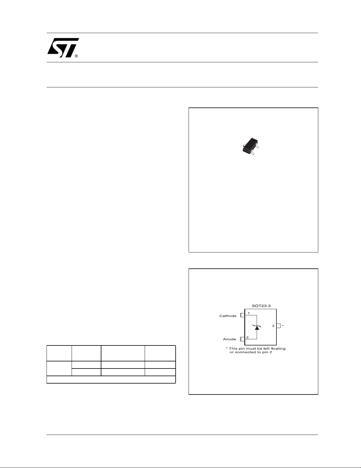
L
SOT23-3L
(Plastic Micropacka ge)
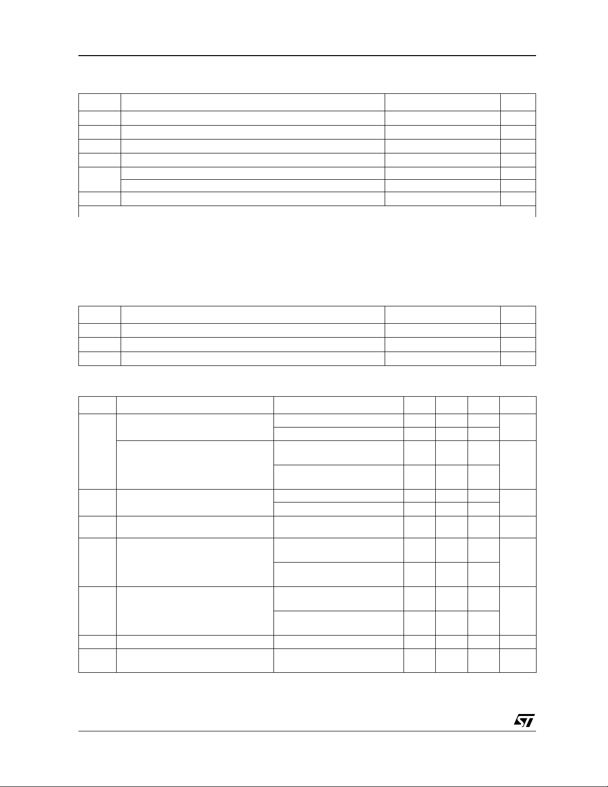
PIN CONNECTIONS (top view)
APPLICATION
■ Instrumentation,
■ Data acquisition systems,
■ Portable, Battery powered equipments
■ Power management
ORDER CODE
Voltage Precision SOT23-3
2.5V
Single temperature range: -40 to +85°C
LT = Tiny Package (SOT23- 3) - only available in Tape & Reel (LT)
March 2002
±1% TS824ILT-2.5 L252
±0.5% TS824AILT-2.5 L253
SOT23
Marking
1/5
Page 2
TS824-2.5
ABSOLUTE MAXIMUM RATINGS
Symbol Parameter Value Unit
I
Reverse Breakdown Current 20 mA
K
I
Forward Current 10 mA
F
P
Power Dissipation (note1) SOT23-3 360 mW
D
T
ESD Human Body Model (HBM) (note2) 2 kV
T
Storage Temperature -65 to +150 °C
Std
Machine Model (MM) (note 2) 200 V
Lead Tempera ture (solde ring, 10 second s) 260 °C
Lead
Note 1: The maximum power dissipation mus t be derated at high temperat ure. It can be ca l culated using T
perat u re), R
temperature is P
Note 2: T he Human Body Model (H B M) is defined as a 100pF capacitor disc harge through a 1.5kΩ resistor into each pin.
The Machine Mode (MM) is defin ed as a 200pF capacitor discharge directly into each pins.
(Thermal resistance junction to ambient) and TA (Ambient temperature). The maximum power dissipation formula at any
THJA
DMAX
= (T
JMAX
- TA) / R
THJA. RTHJA
is 340°C/ W f or the SOT23-3 package.
(max i m um j un c tion tem-
JMAX
OPERATING CONDITIONS
Symbol Parameter Value Unit
I
I
T
Minimum Operating Current 60
min
Maximum Operating Current 15 mA
max
Operating Free Air Temperature Range -40 to +85 °C
oper
ELECTRICAL CHARACTERISTICS (note 3)
= 25°C (unless otherwise specified)
T
amb
Symbol Parameter Test Condition Min. Typ. Max. Unit
= 100µA, ±0.5%
I
Reverse Breakdown Voltage
V
K
Reverse Breakdown Voltage Tolerance
I
Minimum Operating Current
KMIN
Average Temperature Coefficient (note
/∆T
V
∆
K
5)
Reverse Breakdown Voltage Change
/∆I
V
∆
K
K
with Operating Current Range
R
Static Impedance
KA
K
Long Term Stability
VH
E
Wide Band Noise
N
K
= 100µA, ±1%
I
K
= 100µA, ±0.5%
I
K
-40°C < T
I
= 100µA, ±1%
K
-40°C < T
= 25°C
T
amb
-40°C < T
< +85°C
amb
< +85°C
amb
< +85°C
amb
IK = 100µA
< IK < 1mA
I
KMIN
-40°C < T
1mA < I
-40°C < T
= I
I
∆
K
-40°C < T
= 1mA to 15mA
I
∆
K
-40°C < T
I
= 100µA, t = 1000hrs
K
I
= 100µA
K
amb
< 15mA
K
amb
to 1mA
KMIN
amb
amb
< +85°C
< +85°C
< +85°C
< +85°C
100Hz < f < 10kHz
2.4875 2.500 2.5125
2.475 2.500 2.525
-12.5
-20
-25
-33
+12.5
+20
+25
+33
50 60
65
50 ppm/°C
0.4 1
1.2
4.5 8
10
0.4 1
1.2
0.3 0.6
0.7
120 ppm
350 nV/√Hz
mV
mV
A
µ
V
A
µ
Ω
Note 3: Limits are 100% producti on tested at 25 °C. Limits over temperat ure are guaranteed through correlat i on and by design.
Note 4: The total tolerance within the industrial range, where the maximum ∆T versus 2 5°C is 65°C, is explained hereafter:
±
1 % + (± 50 ppm/°C x 65 °C) = ± 1.325 %
2/5
Page 3

TS824-2.5
Reference voltage versus catho de cur rent
3
2
1
Cathode voltage(V)
0
-1
-10 -5 0 5 10 15
Cathode current (mA)
Test circuit
REF
i=0
)/R
R
IK=(VIN-V
Reference voltage versus cathode current
3
T=-40°C
2
1
Cathode voltage (V)
0
0 20406080100
T=+25°C
T=+85°C
Cathode current (µA)
Reference voltage versus Temp eratur e
2.52
2.51
VOUT=VRE F
V
IN
∆V
/∆IK for IK < 1mA versus temperature
K
0.5
∆ V
/ ∆ I
0.4
0.3
(mV)
K
I
∆
/
K
0.2
V
∆
0.1
0.0
-40-200 20406080
Temperature (°C)
I
K MIN
K
< IK < 1 mA
2.50
Reference voltage (V)
2.49
2.48
-40-200 20406080
Temperature (°C)
∆VK/∆IK for IK > 1mA versus temperature
5
K
4
3
(mV)
K
I
∆
/
K
2
V
∆
1
0
-40-200 20406080
Temperature (°C)
∆ V
/ ∆ I
K
1 mA < IK < 15 mA
K
3/5
Page 4

TS824-2.5
Start-up response with low cathode current
5
4
3
Voltage (V)
2
1
0
0 5 10 15 20
Time (µs)
Overshoot
Overshoot versus cathode current
20
T=+25°C
15
10
% of final value
5
Start-up schematic with low cathode current
R
Ik
Pulse
Generator
Intput
Output
Noise versus frequency
500
T
= +25°C
400
Hz)
√
300
200
Noise (nV/
100
AMB
= 100µA
I
K
4/5
0
100 150 200 250 300
Cathode current (µA)
0
100 1k 10k 100k
Frequency (Hz)
Page 5

PACKAGE MECHANICAL DATA
3 PINS - T INY PACKAGE (SOT23-3)
TS824-2.5
E
SEATING
PLANE
C
D
e
E1
b
e1
A2
A1
GAUGE
PLANE
C
0.10
A
0.25
k
L
L1
c
Millimeters Inches
Dimensions
Min. Typ. Max. Min. Typ. Max.
A 0.890 1.120 0.035 0.044
A1 0.010 0.100 0.0004 0.004
A2 0.880 0.950 1.020 0.037 0.040
b 0.300 0.500 0.012 0.020
c 0.080 0.200 0.003 0.008
D 2.800 2.900 3.040 0.110 0.114 0.120
E 2.100 2.640 0.083 0.104
E1 1.200 1.300 1.400 0.047 0.051 0.055
e 0.950 0.037
e1 1.900 0.075
L 0.400 0.500 0.600 0.016 0.020 0.024
L1 0.540 0.021
k 0° 8°
Information furnished is bel ieved to be accurate and reliable. However, STMicroe lectronics assumes no responsibility for the
consequences of use of such information nor for any infringement of patents or other rights of third parties which may result from
its use. No li cense is granted by imp lica tion or otherwise under a ny patent or patent rig hts of STMicroelectronics. Sp ec ificat ions
mentioned in this publication ar e subject to change without notice. This publication supersedes and replaces all information
previously supplied. S TMicroelectronics products are not authorized for use as critica l components in life suppo rt devices or
systems without express written approval of STMicroelectronics.
© The ST logo is a registered trademark of STMicroelectronics
© 2002 STM icroelectronics - Printed in Italy - All Rights Reserv ed
STMicr o el ectronics G ROU P OF COMPANIES
Australi a - Brazil - Canada - Chin a - F i nl and - France - Germany - Hong Kong - Ind i a - Is rael - Ital y - J apan - Malays i a
Malta - Mor occo - Singapore - Spain - Sweden - Switzerland - United Kingdom - United States
© http://www.st.com - United Kingdom
5/5
 Loading...