

Datasheet TPB68, TPB270, TPB240, TPB180, TPB220 Datasheet (SGS Thomson Microelectronics)
...Page 1
TPB SERIES
FEATURES
BIDIRECTIONALCROWBARPROTECTION.
VOLTAGERANGE:FROM 62 V TO270 V.
HOLDINGCURRENT:
=150mAmin.
I
H
REPETITIVEPEAKPULSECURRENT :
I
= 100 A, 10/1000µs.
PP
UL RECOGNIZEDFILE # E136224
DESCRIPTION
The TPB series are TRISIL devicesespecially designed for protecting sensitive telecommunication
equipmentagainstlightning and transientvoltages
induced by AC power lines. They are available in
theCB429 axial package.
TRISILdevices provide bidirectional protectionby
crowbar action. Their characteristic response to
transient overvoltages makes them particularly
suitedtoprotect voltage sensitive telecommunicationequipment.
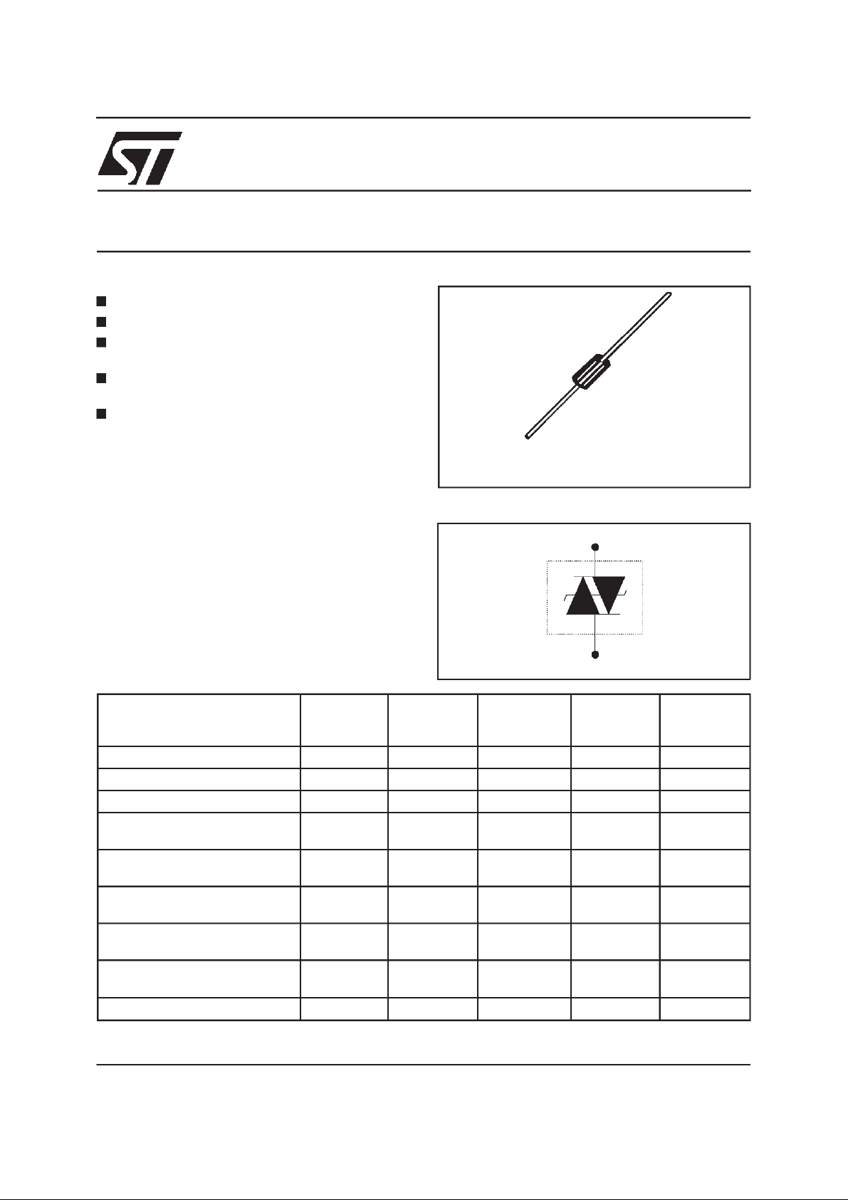
CB429
SCHEMATIC DIAGRAM
TRISIL
TM
COMPLIESWITHTHE
FOLLOWING STANDARDS:
CCITTK20
VDE0433 4000 10/700 5/310 100 VDE0878 4000 1.2/50 1/20 100 IEC-1000-4-5 level4
FCCPart 68, lightningsurge
typeA
FCCPart 68, lightningsurge
typeB
BELLCORETR-NWT-001089
Firstlevel
BELLCORETR-NWT-001089
Secondlevel
CNETl31-24 4000 0.5/700 0.8/310 100 -
October 1998 - Ed: 6A
Peak Surge
Voltage
(V)
4000 10/700 5/310 100 -
level4
1500
800
100 5/320 5/320 25 -
2500
1000
500 2/10 2/10 500 -
Voltage
Waveform
(µs)
10/700
1.2/50
10/160
10/560
2/10
10/1000
Current
Waveform
(µs)
5/310
8/20
10/160
10/560
2/10
10/1000
Admissible
Ipp
(A)
100
100
200
100
500
100
Necessary
Resistor
(Ω)
-
-
-
-
-
-
1/5
Page 2

TPB SERIES
ABSOLUTE MAXIMUM RATINGS(T
Symbol Parameter Value Unit
P Powerdissipationon infiniteheatsink T
I
PP
I
TSM
2
tI
I
Peak pulsecurrent 10/1000µs
Non repetitivesurge peak on-statecurrent tp = 20 ms 50 A
2
t valueforfusing tp = 20 ms 25 A2s
dV/dt Criticalrate of riseof off-statevoltage V
T
stg
T
j
T
L
Storagetemperaturerange
Maximumjunctiontemperature
Maximumleadtemperaturefor soldering during 10s at 5mm for
case
THERMALRESISTANCES
Symbol Parameter Value Unit
(j-l) Junctionto leads(L
R
th
(j-a)
R
th
Junctionto ambient on printed circuit(L
lead
ELECTRICAL CHARACTERISTICS
(T
=25°C)
amb
=25°C)
amb
=50 °C5 W
amb
100
8/20 µs
2/10 µs
RM
150
500
5kV/µs
- 55 to+ 150
150
230 °C
= 10mm) 20 °C/W
lead
= 10 mm)
75 °C/W
A
°C
°C
Symbol Parameter
V
RM
I
RM
V
V
BR
V
BO
I
H
I
BO
I
PP
C
Type I
TPB62
TPB68
TPB100
TPB120
TPB130
TPB180
TPB200
TPB220
TPB240
TPB270
Note 1: IRmeasuredat VRguarantees V
Note 3: See test circuit 2. Note 4: V
2/5
Stand-offvoltage
Leakagecurrentat stand-offvoltage
ContinuousReverse voltage
R
Breakdownvoltage
Breakovervoltage
Holdingcurrent
Breakovercurrent
Peakpulse current
Capacitance
@V
RM
RM
max. max.
AV
µ
2
2
2
2
2
2
2
2
2
2
56
61
90
108
117
162
180
198
216
243
BRmin≥VR
IR@V
R
max.
note1
AV VmAmApF
µ
50
50
50
50
50
50
50
50
50
50
62
68
100
120
130
180
200
220
240
270
note2
82
90
133
160
173
240
267
293
320
360
Note 2: Measured at 50 Hz (1 cycle) - See test circuit 1.
VBO@I
BO
I
H
min.
note3
800
800
800
800
800
800
800
800
800
800
= 1V, F = 1MHz, refer tofig.3 for C versus V
R
150
150
150
150
150
150
150
150
150
150
C
max.
note4
300
300
200
200
200
200
200
200
200
200
R.
Page 3

TESTCIRCUIT 1 FORIBOandVBOparameters:
Auto
Transformer
220V/ 2A
static
relay.
V
out
220V
Transforme r
220V/ 800V
5A
TESTPROCEDURE:
PulseTest duration (tp = 20ms):
- ForBidirectionaldevices= SwitchK isclosed
- ForUnidirectionaldevices= SwitchK is open.
V
Selection
OUT
- Devicewith V
-V
- Devicewith V
-V
BO
OUT
BO
OUT
≤ 200 Volt
=250 V
≥ 200Volt
= 480 V
RMS,R1
RMS,R2
= 140 Ω.
= 240 Ω.
= 20ms
tp
K
I
BO
measure
R1
140
R2
240
D.U.T
V
BO
measure
TPB SERIES
TESTCIRCUIT 2 for I
parameter
H
R
D.U.T.
V
= - 48 V
BAT
This is a GO-NOGO testwhich allows to confirmthe holdingcurrent(I
TESTPROCEDURE:
- Adjustthe currentlevel at theI
- Firethe D.U.T. with a surgecurrent: I
value byshort circuitingthe D.U.T.
H
=10A, 10/1000 µs.
pp
- TheD.U.T.will comeback to the off-statewithin 50 ms max.
-V
P
Surge generator
)level in a functionaltest circuit.
H
3/5
Page 4

TPB SERIES
Fig.1:
Non repetitive surge peak on-statecurrent
versus overload duration (Tj initial=25°C).
Fig. 3: Relative variation of junction capacitance
versus reverse applied voltage(typical values).
Note: For V
upper than 56V, the curve is
RM
extrapolated(dotted line).
Fig. 2:
Relativevariation of holding current versus
junctiontemperature.
Fig. 4: On-state current versus on-state voltage
(typicalvalues).
Fig. 5: Transient thermal impedance junction to
ambient versus pulse duration (for FR4 PC Board
Lead
= 10 mm).
withT
4/5
Page 5

ORDERCODE
TPB SERIES
TPB 100 RL
TRISILPROTECTION100A
BREAKDOWNVOLTAGE
MARKING :
Logo, Date Code, Part Number.
PACKAGEMECHANICALDATA.
CB429 Plastic
CA
O
O
/D
/D
C
/
PACKAGING:
RL= tapeand reel.
BO
= Ammopack.
DIMENSIONS
REF.
Millimeters Inches
Min. Typ. Max. Min. Typ. Max.
A 9.45 9.50 9.80 0.372 0.374 0.386
B 26 1.024
∅ C 4.90 5.00 5.10 0.193 0.197 0.201
∅ D 0.94 1.00 1.06 0.037 0.039 0.042
L1 1.27 0.050
note1
: the leadis not controlledin zoneL
1
Packaging: Standardpackagingisintapeandreel.
Weight
Informationfurnished is believedto be accurate and reliable. However, STMicroelectronics assumes no responsIbility for the consequences of
use ofsuch information nor forany infringementof patentsor other rightsof thirdparties which mayresult from its use. Nolicense is granted by
implication or otherwise under any patent or patent rights of STMicroelectronics. Specifications mentioned in this publication are subject to
change without notice. This publication supersedes and replaces all information previously supplied.
STMicroelectronics products are not authorized for use as critical components in life support devices or systems without express written approval ofSTMicroelectronics.
Australia - Brazil - Canada - China - France - Germany - Italy - Japan - Korea -Malaysia - Malta - Mexico - Morocco -
:0.85g
The ST logo is a registeredtrademark of STMicroelectronics
1998STMicroelectronics- Printed in Italy - All rights reserved.
STMicroelectronics GROUP OF COMPANIES
The Netherlands - Singapore - Spain - Sweden - Switzerland - Taiwan - Thailand - United Kingdom - U.S.A.
http://www.st.com
5/5
 Loading...