

Page 1

User’s Guide
2001 Mixed-Signal Products
SLOU083A
Page 2

Information About Cautions and Warnings
This book may contain cautions and warnings.
This is an example of a caution statement.
A caution statement describes a situation that could potentially
damage your software or equipment.
Information About Cautions and Warnings
Preface
Read This First
This is an example of a warning statement.
A warning statement describes a situation that could potentially
cause harm to you
The information in a caution or a warning is provided for your protection.
Please read each caution and warning carefully.
.
Related Documentation From Texas Instruments
J TI Plug-N-Play Audio Amplifier Evaluation Platform (literature
number SLOU011) provides detailed information on the evaluation
platform and its use with TI audio evaluation modules.
J TPA2000D1 2-W Mono Class-D Audio Power Amplifier
(literature number SLOS328) This is the data sheet for the
TPA2000D1 audio amplifier integrated circuit.
Read This First
iii
Page 3

Running Title—Attribute Reference
FCC Warning
This equipment is intended for use in a laboratory test environment only. It
generates, uses, and can radiate radio frequency energy and has not been
tested for compliance with the limits of computing devices pursuant to subpart
J of part 15 of FCC rules, which are designed to provide reasonable protection
against radio frequency interference. Operation of this equipment in other
environments may cause interference with radio communications, in which
case the user at his own expense will be required to take whatever measures
may be required to correct this interference.
iv
Page 4

Running Title—Attribute Reference
Contents
1 Introduction 1-1. . . . . . . . . . . . . . . . . . . . . . . . . . . . . . . . . . . . . . . . . . . . . . . . . . . . . . . . . . . . . . . . . . . . .
1.1 Feature Highlights 1-2. . . . . . . . . . . . . . . . . . . . . . . . . . . . . . . . . . . . . . . . . . . . . . . . . . . . . . . . . .
1.2 Description 1-3. . . . . . . . . . . . . . . . . . . . . . . . . . . . . . . . . . . . . . . . . . . . . . . . . . . . . . . . . . . . . . . .
1.3 TP A2000D1 EVM Specifications 1-4. . . . . . . . . . . . . . . . . . . . . . . . . . . . . . . . . . . . . . . . . . . . . .
2 Operation 2-1. . . . . . . . . . . . . . . . . . . . . . . . . . . . . . . . . . . . . . . . . . . . . . . . . . . . . . . . . . . . . . . . . . . . . . .
2.1 Precautions 2-2. . . . . . . . . . . . . . . . . . . . . . . . . . . . . . . . . . . . . . . . . . . . . . . . . . . . . . . . . . . . . . . .
2.2 Quick Start List for Platform 2-3. . . . . . . . . . . . . . . . . . . . . . . . . . . . . . . . . . . . . . . . . . . . . . . . . .
2.3 Quick Start List for Stand-Alone 2-5. . . . . . . . . . . . . . . . . . . . . . . . . . . . . . . . . . . . . . . . . . . . . .
2.4 Reference 2-7. . . . . . . . . . . . . . . . . . . . . . . . . . . . . . . . . . . . . . . . . . . . . . . . . . . . . . . . . . . . . . . . .
2.4.1 TPA2000D1 Filterless Class-D EVM Schematic 2-7. . . . . . . . . . . . . . . . . . . . . . . . .
2.4.2 TPA2000D1 Audio Power Amplifier Evaluation Module Parts List 2-8. . . . . . . . . .
2.4.3 TPA2000D1 Filterless Class-D EVM PCB Layers 2-9. . . . . . . . . . . . . . . . . . . . . . . .
Figures
1–1 The TI TPA2000D1 Audio Amplifier EVM Without Output Filter—Top View 1-3. . . . . . . . . . . .
2–1 Quick Start Platform Map 2-2. . . . . . . . . . . . . . . . . . . . . . . . . . . . . . . . . . . . . . . . . . . . . . . . . . . . . .
2–2 Module Preparation 2-4. . . . . . . . . . . . . . . . . . . . . . . . . . . . . . . . . . . . . . . . . . . . . . . . . . . . . . . . . . .
2–3 Quick Start Module Map 2-5. . . . . . . . . . . . . . . . . . . . . . . . . . . . . . . . . . . . . . . . . . . . . . . . . . . . . . .
2–4 TPA2000D1 Class-D EVM Schematic Diagram 2-7. . . . . . . . . . . . . . . . . . . . . . . . . . . . . . . . . . .
2–5 TPA2000D1 Filterless Class-D EVM Top Layer 2-9. . . . . . . . . . . . . . . . . . . . . . . . . . . . . . . . . . . .
2–6 TPA2000D1 FIlterless Class-D EVM Bottom Layer 2-9. . . . . . . . . . . . . . . . . . . . . . . . . . . . . . . .
Tables
2–1 Typical TI Plug-N-Play Platform Jumper and Switch Settings for the TPA2000D1 2-1. . . . . .
2–2 Typical TPA2000D1 EVM Jumper Settings 2-1. . . . . . . . . . . . . . . . . . . . . . . . . . . . . . . . . . . . . . .
2–3 Platform Jumper and Switch Settings for the TPA2000D1 2-3. . . . . . . . . . . . . . . . . . . . . . . . . .
2–4 Typical TPA2000D1 EVM Jumper Settings 2-4. . . . . . . . . . . . . . . . . . . . . . . . . . . . . . . . . . . . . . .
2–5 TPA2000D1 EVM Gain Settings 2-6. . . . . . . . . . . . . . . . . . . . . . . . . . . . . . . . . . . . . . . . . . . . . . . . .
2–6 TPA2000D1 EVM Parts List 2-8. . . . . . . . . . . . . . . . . . . . . . . . . . . . . . . . . . . . . . . . . . . . . . . . . . . .
Contents
v
Page 5

vi
Page 6

Chapter 1
Introduction
This chapter provides an overview of the Texas Instruments (TI) TPA2000D1
filterless class-D audio amplifier evaluation module (SLOU083). It includes a
list of EVM features, a brief description of the module illustrated with a pictorial
diagram, and a list of EVM specifications.
Topic Page
1.1 Feature Highlights 1–2. . . . . . . . . . . . . . . . . . . . . . . . . . . . . . . . . . . . . . . . . . . .
1.2 Description 1–3. . . . . . . . . . . . . . . . . . . . . . . . . . . . . . . . . . . . . . . . . . . . . . . . . . .
1.3 TP A2000D1 EVM Specifications 1–4. . . . . . . . . . . . . . . . . . . . . . . . . . . . . . . .
Introduction
1-1
Page 7

Feature Highlights
1.1 Feature Highlights
The TI TP A2000D1 audio amplifier evaluation module and the TI plug-n-play
audio amplifier evaluation platform include the following features:
- TPA2000D1 Mono 2-W Filterless Class-D Audio Power Amplifier
Evaluation Module
J Class-D without output filter
J 2.7 V to 5.5 V supply voltage range
J Internal depop circuitry to minimize transients in outputs
J High efficiency
J Low distortion
J Low-supply current (5 mA)
J 2-W output power into 4 Ω at 5 V
J Low current consumption in shutdown mode
J Four selectable gain settings: 6, 12, 17.5, and 23.5 dB
J Differential stereo input
J 16-pin TSSOP PWP package
- Quick and Easy Configuration With the TI Plug-N-Play Audio Amplifier
Evaluation Platform
J Evaluation module is designed to simply plug into the platform,
automatically making all signal, control, and power connections.
J Platform provides flexible power options
J Jumpers on the platform select power and module control options
J Switches on the platform route signals
J Platform provides quick and easy audio input and output connections
- Platform Power Options
J External 5-V – 15-V dc V
J External regulated V
J Socket for onboard 5 V/3.3 V V
J Onboard overvoltage and reverse polarity power protection
- Platform Audio Input and Output Connections
J Left and right RCA phono jack inputs
DD
supply inputs
CC
supply input
voltage regulator EVM
DD
J Miniature stereo phone jack input
J Left and right RCA phono jack outputs
J Left and right compression speaker terminal outputs
J Miniature stereo headphone jack output
1-2
Introduction
Page 8
Description
1.2 Description
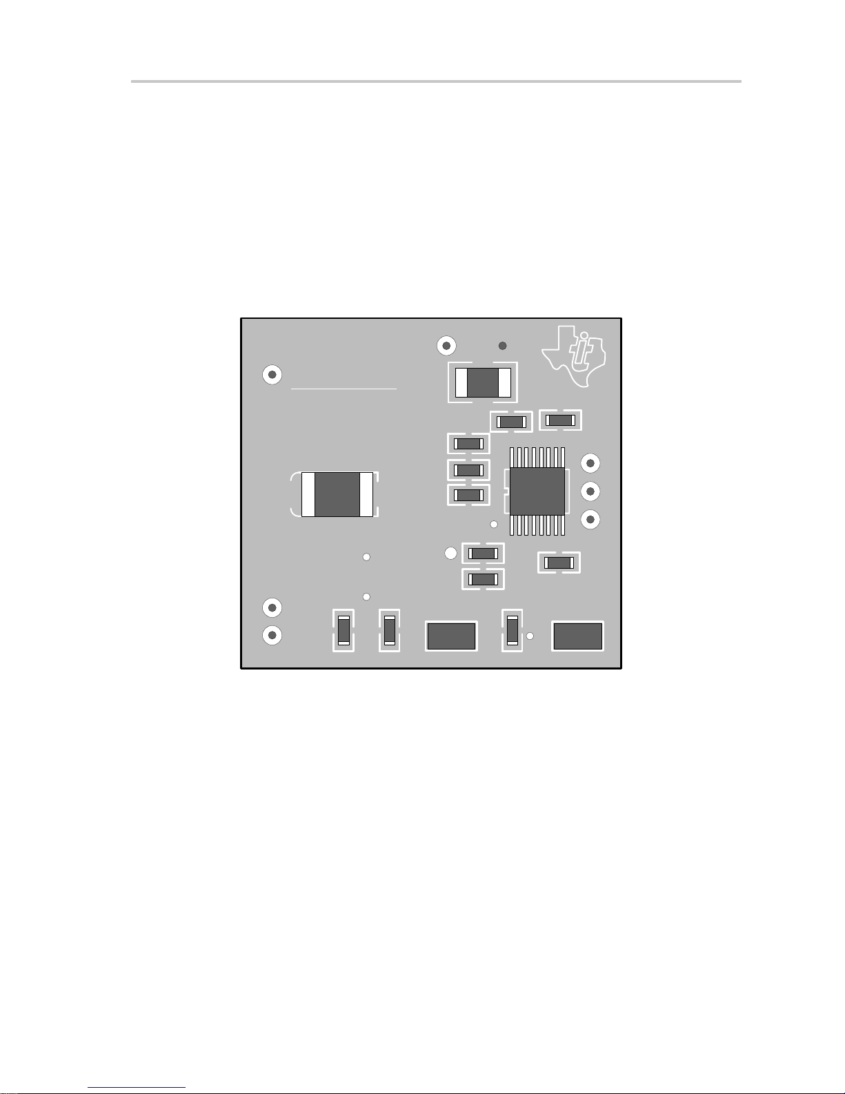
The TPA2000D1 filterless class-D mono audio power amplifier evaluation
module is a complete, 2-W class-D audio power amplifier that can operate
without an output filter. It consists of the TI TPA2000D1 class-D mono 2-W
audio power amplifier IC along with a small number of other parts mounted on
a circuit board that measures approximately 1-1/4 inches by 1-1/4 inches (see
Figure 1–1.
Figure 1–1.The TI TPA2000D1 Audio Amplifier EVM Without Output Filter—Top View
TEXAS
VDD GND
INSTRUMENTS
TPA2000D1 EVM
SHUTDOWN
SLOP327
R1
C1
S1
C6
C8
C5
OUT+
GND
C7
U1
OUT–
C2
C4
C3
IN+
R2 R3
GAIN0
R4
GAIN1
IN–
J1
Single in-line header pins extend from the underside of the module circuit
board to allow the EVM to be plugged into the TI plug-n-play audio amplifier
evaluation platform, or to be wired directly into existing circuits and equipment
when used stand-alone.
J2
The platform has room for two TPA2000D1 evaluation modules and is a
convenient vehicle for demonstrating TI’s audio power amplifier and related
evaluation modules. The EVMs simply plug into the platform, which
automatically provides power to the modules, interconnects them correctly,
and connects them to a versatile array of standard audio input and output jacks
and connectors. Easy-to-use configuration controls allow the platform and
EVMs to quickly model many possible end-equipment configurations.
There is nothing to build, nothing to solder, and nothing but the speakers
included with the platform to hook up.
Introduction
1-3
Page 9

TP A2000D1 EVM Specifications
1.3 TPA2000D1 EVM Specifications
Supply voltage range, V
Supply current, I
DD
DD
Continuous output power per channel, P
Minimum load impedance, R
L
: 4 Ω, V
O
2.7 V to 5.5 V. . . . . . . . . . . . . . . . . . . . . . . . . . . . . . . . . . . . . . . . . . . . . .
= 5 V 2 W. . . . . . . . . . . . . . . . . . . . . . . . . . .
DD
2 A max. . . . . . . . . . . . . . . . . . . . . . . . . . . . . . . . . . . . . . . . . . . . . . . . . . . . . . . . . .
4 Ω. . . . . . . . . . . . . . . . . . . . . . . . . . . . . . . . . . . . . . . . . . . . . . . . . . . . .
1-4
Introduction
Page 10

Chapter 2
Operation
The steps in this chapter can be followed to quickly prepare the TP A2000D1
filterless class-D audio amplifier EVM for use. Using the TP A2000D1 with the
TI plug-n-play audio amplifier evaluation platform is a quick and easy way to
connect power, signal and control inputs, and signal outputs to the EVM using
standard connectors. However, the audio amplifier evaluation module can be
used stand-alone by making connections directly to the module pins, and can
be wired directly into existing circuits or equipment.
The platform switch and jumper settings shown in T able 2–1 are typical for the
TPA2000D1 EVM and will cause the TPA2000D1 to shut down when a plug
is inserted into platform headphone jack J10.
Table 2–1. Typical TI Plug-N-Play Platform Jumper and Switch Settings for the
TPA2000D1
EVM JP4 JP5 JP6 JP7 JP8 S2 S3
P-N-P Platform X ON Mute X Lo See Note 2 U5
Notes: 1) ON = Jumper installed, OFF = Jumper NOT Installed, X = Don’t care
2) Set S2 to ON when signal conditioning board is installed in U1; set S2
to OFF when no signal conditioning board is installed.
Table 2–2. Typical TPA2000D1 EVM Jumper Settings
EVM GAIN0 GAIN1
TPA2000D1 ON ON
Note: ON = Jumper installed, OFF = Jumper NOT Installed, X = Don’t care
Topic Page
2.1 Precautions 2–2. . . . . . . . . . . . . . . . . . . . . . . . . . . . . . . . . . . . . . . . . . . . . . . . . .
2.2 Quick Start List for Platform 2–3. . . . . . . . . . . . . . . . . . . . . . . . . . . . . . . . . . .
2.3 Quick Start List for Stand-Alone 2–5. . . . . . . . . . . . . . . . . . . . . . . . . . . . . . . .
2.4 Reference 2–7. . . . . . . . . . . . . . . . . . . . . . . . . . . . . . . . . . . . . . . . . . . . . . . . . . . .
Operation
2-1
Page 11
Precautions
2.1 Precautions
Power Supply Input Polarity and Maximum Voltage
Always ensure that the polarity and voltage of the external power
connected to V
input connector J6 are correct. Overvoltage or reverse-polarity
power applied to these terminals can open onboard soldered-in
fuses and cause other damage to the platform, installed evaluation
modules, and/or the power source.
Inserting or Removing EVM Boards
Do not insert or remove EVM boards with power applied—damage
to the EVM board, the platform, or both may result.
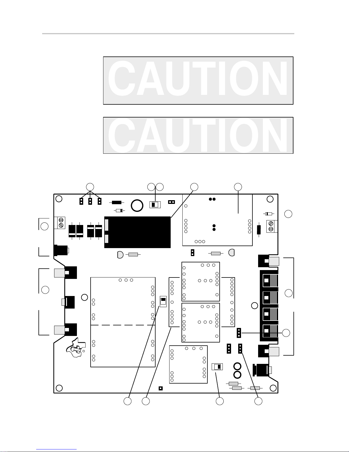
Figure 2–1.Quick Start Platform Map
power input connector J1, J2, and/or VDD power
CC
Power
Input
Audio
Input
7b
Off Pwr
1
13
On
ICC
JP4
S1
7b 7b
SUPPLY
POWER
U6
F2
VR2
7a
7b
SOURCE
J1
VCC
In
+
DC
VCC(J1)
JP1
(J2)
JP2
AC/DC
Batt
JP3
VR1
F1
C1+
DC
D4 J2
AC/DC
In
In
Right
J3
D3
D2
D1
LED1
VCC
R1
Signal Conditioning
Stereo
J4
9
In
U1
B1
Audio
Power
Amps
IDD
JP5
U3 U4
R2
U2
LED2
VDD
Out
J7
Right
J8
Out
+ – +–
Right
In/Out
VDD
J6
Power
In/Out
+
10
Speaker
Output
5
Headphone
Output
Left
J5
In
TEXAS
INSTRUMENTS
1997
****CAUTION****
Do not insert or remove
EVM boards with power
applied
Plug-N-Play Audio Amplifier
Evaluation Platform
SLOP097 Rev. C.1
ConditioningS2
GND
OnOff
TP1
U5
U2-U4
U5
HP
Source
HP(U5)
S3
R4
JP6
Polarity
Lo
Hi
JP7
+
+
R3
Out
Mode
Mute
Spk(U2-U4)
Out
JP8
C3 C2
HP Out
Left
J9
Left
Stereo
J10
R5
2-2
23 4
6
Operation
Page 12

2.2 Quick Start List for Platform
Follow these steps when using the TPA2000D1 EVM with the TI plug-n-play
audio amplifier evaluation platform (see the platform user’s guide, literature
number SLOU011, for additional details). Numbered callouts for selected
steps are shown in Figure 2–1 and Figure 2–2.
- Platform preparations
1) Ensure that all external power sources are set to OFF and that the platform
power switch S1 is set to OFF.
2) Install a TPA2000D1 module in platform socket U3 or U4, taking care to
align the module pins correctly.
3) Use switch S2 to select or bypass the signal conditioning EVM (U1).
4) Set control signal polarity jumper JP8 to Lo.
5) Set jumper JP6 to select the Mute control input (causes the TPA2000D1
to shut down if a plug is inserted into platform headphone jack J10).
6) If a headphone amplifier will be installed in U5, set the headphone source
switch S3 to U5.
Quick Start List for Platform
Table 2–3. Platform Jumper and Switch Settings for the TPA2000D1
EVM JP4 JP5 JP6 JP7 JP8 S2 S3
P-N-P Platform X ON Mute X Lo Note 2 U5
Notes: 1) ON = Jumper installed, OFF = Jumper NOT Installed, X = Don’t care
2) Set S2 to ON when signal conditioning board is installed in U1; set S2
to OFF when no signal conditioning board is installed.
- Power supply
7) Select and connect the power supply (ensure power supply is set to OFF ):
a) Connect an external regulated power supply set to 5 V to platform V
power input connector J6 taking care to observe marked polarity.
or
b) Install a voltage regulator EVM (SLVP097 or equiv .) in platform socket
U6. Connect a 7-V – 12-V power source to a platform V
J1 or J2 and jumper the appropriate power input (see platform user’s
guide). If using J1, J2, or B1, set S1 to ON to supply power to the EVM.
- Inputs and outputs
8) Ensure that the audio signal source level is set to minimum.
9) Connect the audio source to left or right RCA phono jacks J3 or J5 or
stereo miniature phone jack J4.
power input
CC
DD
10) Connect a speaker to left or right RCA jacks J7 or J9 or to stripped wire
speaker connectors J8.
Operation
2-3
Page 13
Quick Start List for Platform
- Evaluation Module Preparations
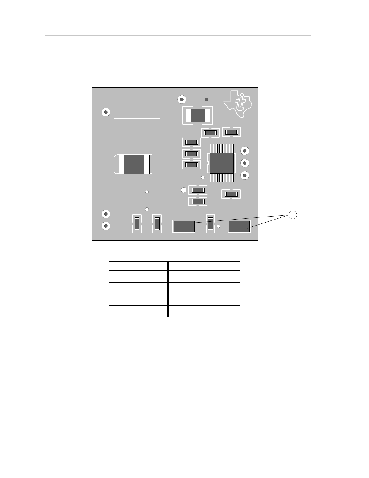
11) Use jumpers GAIN0 and GAIN1 to set the gain (see Figure 2–2 and
Table 2–4).
Figure 2–2.Module Preparation
TEXAS
VDD GND
INSTRUMENTS
TPA2000D1 EVM
SHUTDOWN
SLOP327
C6
R1
C1
S1
C7
U1
C2
C3
R2 R3
IN+
GAIN0
IN–
J1
Table 2–4. Typical TPA2000D1 EVM Jumper Settings
GAIN1 GAIN0 GAIN (dB)
ON ON 6
C4
R4
C8
J2
C5
OUT+
OUT–
GAIN1
GND
11
2-4
ON OF 12
OFF ON 17.5
OFF OFF 23.5
Note: ON = Jumper installed, OFF = Open, X = Don’t care
- Power Up
12) Verify correct voltage and input polarity and set the external power supply
to ON. If V
platform power switch S1 to ON.
Platform LED2 should light indicating the presence of V
modules installed on the platform should begin operation.
13) Adjust the signal source level as needed.
and an onboard regulator EVM are used to provide VDD, set
CC
, and the evaluation
DD
Operation
Page 14
2.3 Quick Start List for Stand-Alone
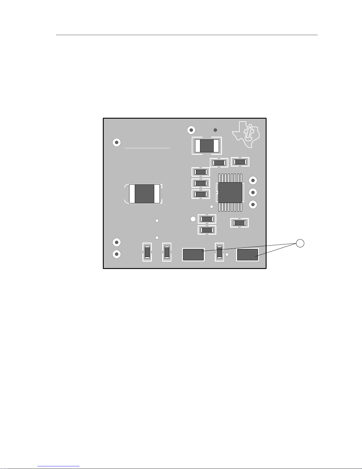
Follow these steps to use the TPA2000D1 EVM stand-alone or when
connecting it into existing circuits or equipment. Connections to the
TPA2000D1 module header pins can be made via individual sockets,
wire-wrapping, or soldering to the pins, either on the top or the bottom of the
module circuit board. Numbered callouts for selected steps are shown in
Figure 2–3.
Figure 2–3.Quick Start Module Map
Quick Start List for Stand-Alone
TEXAS
VDD GND
INSTRUMENTS
TPA2000D1 EVM
SHUTDOWN
SLOP327
R1
C1
S1
C6
C8
C5
OUT+
GND
C7
U1
OUT–
C2
C4
C3
IN+
R2 R3
GAIN0
R4
GAIN1
IN–
J1
- Power supply
1) Ensure that all external power sources are set to OFF.
J2
1
2) Connect an external regulated power supply set to 5 V to the module VDD
- Inputs and outputs
3) Ensure that audio signal source level adjustments are set to minimum.
4) Connect the positive lead of the audio source to the module IN+ pins and
5) Connect a speaker to OUT+ and OUT–.
- Evaluation module preparations
6) Use jumpers GAIN0 and GAIN1 to set the gain as shown in Table 2–5.
and GND pins taking care to observe marked polarity.
the negative lead to the IN– pin.
Operation
2-5
Page 15

Quick Start List for Stand-Alone
Table 2–5. TPA2000D1 EVM Gain Settings
GAIN1 GAIN0 GAIN (dB)
ON ON 6
ON OF 12
OFF ON 17.5
OFF OFF 23.5
Note: ON = Jumper installed, OFF = Open, X = Don’t care
- Control inputs
7) SHUTDOWN
allows normal operation.
- Power up
8) Connect external power supply set to 5 V across EVM VDD and GND pins.
9) Verify correct voltage and input polarity and set the external power supply
to ON.
The EVM should begin operation.
10) Adjust the signal source level as needed.
: A low shuts down the amplifier IC on the module; a high
2-6
Operation
Page 16
2.4 Reference
2.4.1 TPA2000D1 Filterless Class-D EVM Schematic
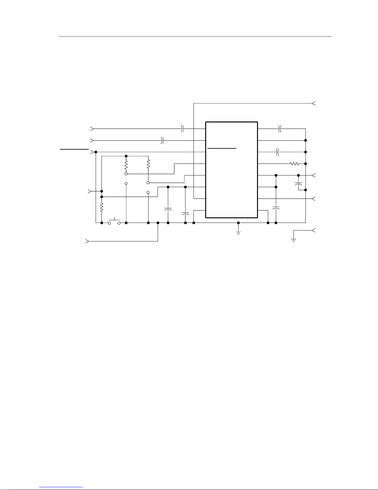
The TPA2000D1 filterless class-D EVM schematic is shown in Figure 2–4.
Figure 2–4.TPA2000D1 Class-D EVM Schematic Diagram
U1
IN–
IN+
SHUTDOWN
V
DD
R2
120 kΩ
J1
R3
120 kΩ
J2
1 µF
R4
120 kΩ
C8
10 µF
C3
C2
1 µF
C4
1 µF
1
INP
2
INN
3
SHUTDOWN
4
GAIN0
5
GAIN1
6
PV
DD
7
OUTP
8
GNDP
TPA2000D1
BYPASS
AGND
COSC
ROSC
V
DD
PV
DD
OUTN
GNDN
16
15
14
13
12
11
10
9
C7
1 µF
C1
220 pF
120 kΩ
C6
1 µF
C5
1 µF
R1
Reference
OUT–
V
DD
OUT+
GND
S1
GND
Operation
2-7
Page 17

TP A2000D1 Audio Power Amplifier Evaluation Module Parts List
2.4.2 TPA2000D1 Audio Power Amplifier Evaluation Module Parts List
Table 2–6.TPA2000D1 EVM Parts List
Reference Description Size
C1 Capacitor, ceramic, 220 pF, ±5%,
X7R, 50 V
C2–7 Capacitor, ceramic, 1.0 µF,
80%/–20%, Y5V, 16 V
C8 Capacitor, ceramic, 10 µF,
80%/–20%, Y5V, 16 V
R1–R4 Resistor, chip, 120 kΩ, 1/10 W,
5%, XICON
S1 Switch, momentary pushbutton,
12 V, 50 mA
J1, J2 Header, 2 position 2 mm 2 Norcomp
Shunts 2 mm 2 3M
Headers, 0.100 inch centers, 1/2
length, 0.1 inch center
U1 IC, 2 W, class–D audio power
amp
603 1 Phillips
603 6 Panasonic
1210 1 Murata
0805 4 Mouser
0.291 x 0.138 x
0.134”
0.5”, 0.25”, 0.1” 8 Samtec
16-pin TSSOP 1 TI
EVM
Qty.
06032R221K9B20D
ECJ–1VF1A105Z
GRM235-Y5V106Z16
260–120K
1 Panasonic
EVQ–PJS04K
2163–02–ND(Digi–Key)
2163–02–ND(Digi–Key)
TSW–19–8–G–S
TPA2000D1PW
Manufacturer/
Part Number
PCB PCB, 2 layer, 1.32”(L) x 1.22”(W)
x 0.062”(T) fits U3 on PnP
1 TI
SLOP327
2-8
Operation
Page 18
TPA2000D1 Filterless Class-D EVM PCB Layers
2.4.3 TPA2000D1 Filterless Class-D EVM PCB Layers
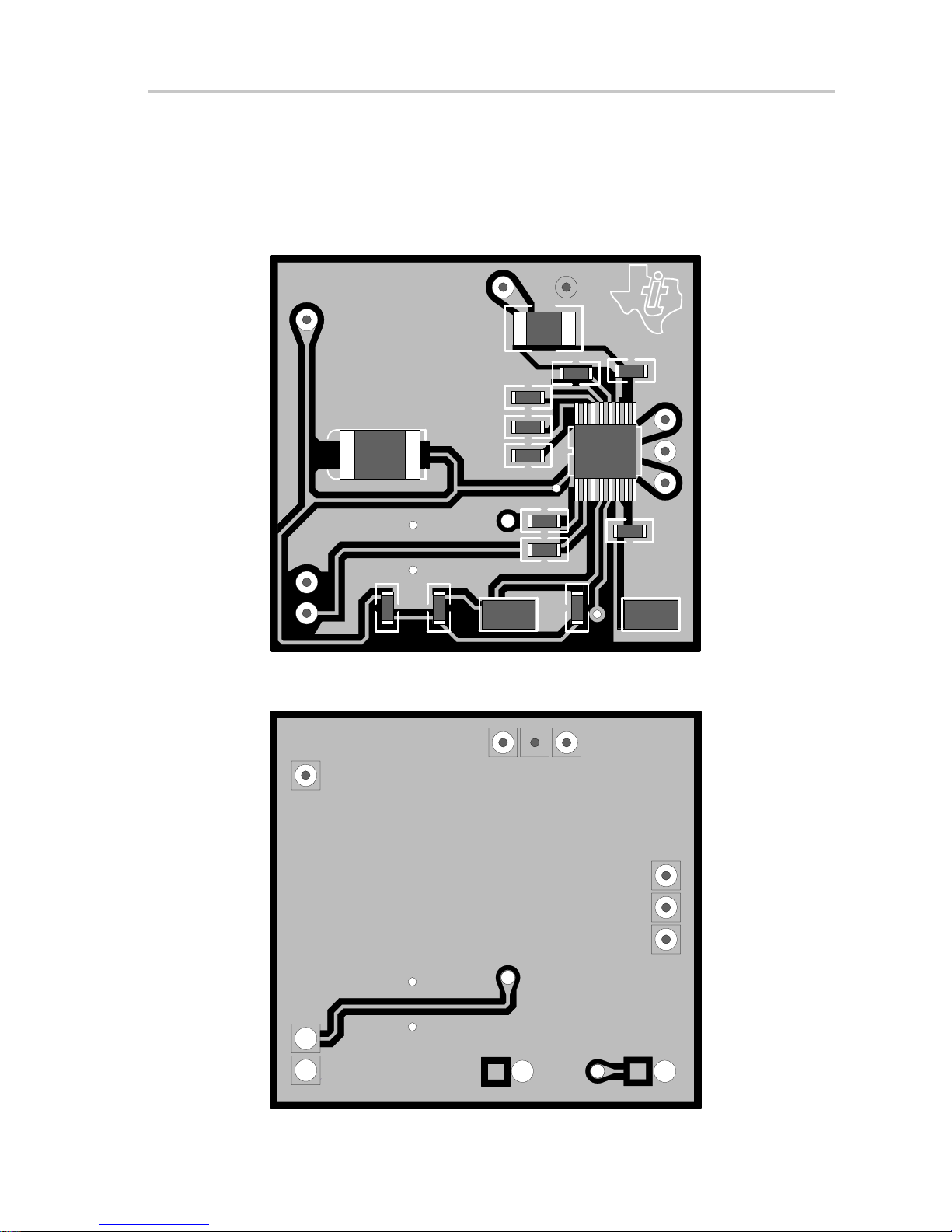
The following illustrations depict the TPA2000D1 filterless class-D EVM PCB
layers. These drawings are not to scale. Gerber plots can be obtained from any
TI sales office.
Figure 2–5.TPA2000D1 Filterless Class-D EVM Top Layer
TEXAS
VDD GND
INSTRUMENTS
TPA2000D1 EVM
SHUTDOWN
SLOP327
R1
C1
S1
C6
C8
C5
OUT+
C7
U1
OUT–
C2
C4
C3
IN+
R2 R3
GAIN0
R4
GAIN1
IN–
J1
Figure 2–6.TPA2000D1 Filterless Class-D EVM Bottom Layer (Top View)
J2
GND
Operation
2-9
Page 19

2-10
Operation
Page 20

IMPORTANT NOTICE
Texas Instruments and its subsidiaries (TI) reserve the right to make changes to their products
or to discontinue any product or service without notice, and advise customers to obtain the latest
version of relevant information to verify , before placing orders, that information being relied on
is current and complete. All products are sold subject to the terms and conditions of sale supplied
at the time of order acknowledgment, including those pertaining to warranty , patent infringement,
and limitation of liability .
TI warrants performance of its products to the specifications applicable at the time of sale in
accordance with TI’s standard warranty . T esting and other quality control techniques are utilized
to the extent TI deems necessary to support this warranty . Specific testing of all parameters of
each device is not necessarily performed, except those mandated by government requirements.
Customers are responsible for their applications using TI components.
In order to minimize risks associated with the customer’s applications, adequate design and
operating safeguards must be provided by the customer to minimize inherent or procedural
hazards.
TI assumes no liability for applications assistance or customer product design. TI does not
warrant or represent that any license, either express or implied, is granted under any patent right,
copyright, mask work right, or other intellectual property right of TI covering or relating to any
combination, machine, or process in which such products or services might be or are used. TI’s
publication of information regarding any third party’s products or services does not constitute TI’s
approval, license, warranty or endorsement thereof.
Reproduction of information in TI data books or data sheets is permissible only if reproduction
is without alteration and is accompanied by all associated warranties, conditions, limitations and
notices. Representation or reproduction of this information with alteration voids all warranties
provided for an associated TI product or service, is an unfair and deceptive business practice,
and TI is not responsible nor liable for any such use.
Resale of TI’s products or services with statements different from or beyond the parameters
stated by TI for that product or service voids all express and any implied warranties for the
associated TI product or service, is an unfair and deceptive business practice, and TI is not
responsible nor liable for any such use.
Also see: Standard Terms and Conditions of Sale for Semiconductor Products.
www.ti.com/sc/docs/stdterms.htm
Mailing Address:
Texas Instruments
Post Office Box 655303
Dallas, Texas 75265
Copyright 2001, Texas Instruments Incorporated
2-12
 Loading...