

Page 1

_______________________________________________________________________________
This specification is subject to be changed without notice.
1
TP8452
PS/2 MOUSE CONTROLLER
General Description
The TP8452 Mouse Controller is specially designed to control PS/2 mouse device. This single chip
can interface three key-switches and four photo-couples direct to 8042. TP8452 can receive command
and echo status or data format which are compatible with IBM PS/2 mode mouse.
Key debouncing circuit is provided to prevent false entry and improve TP8452 accuracy.
In the conventional mouse, a great number of noises are generated when the grid is partially closed or
opened. These noises are usually mistaken for movement signals by conventional mouse controller
and the cursor of the display screen is thus moved frequently up and down or back and forth. This will
consumes a great amount of energy. The TP8452 PS/2 mouse controller provides noise immunity
circuits to eliminate these noises in order to reduce energy consumption.
Using the auto-speed adjusting circuits, TP8452 promotes the power of the mouse in movement. when
TP8452 moves at low speed, it will be very smooth. While at high speed, TP8452 can change the
scanning ability of the motion and detects more dots than that of at low speed. According to different
speed, the horizontal and vertical counters acquire different dots in the same distance.
Features
* Being compatible with PS/2 mouse mode.
* Including buyer testing mode.
* Auto speed with dynamic resolutions.
* Built-in noise immunity circuit.
* Low power dissipation.
* Both RC oscillating and crystal oscillating circuits provided.
* Three key-switches and four photo-couples inputs.
* Both key-press and key-release debounce interval 11 ms.
* Through three key-switch inputs, TP8452 can exert seven different output.
* PIN to PIN compatible with HM8450.
* Improved ESD protection.
Applications
* Optical mouse or pen-mouse.
* Mechanical mouse or pen-mouse.
* Optomechanical mouse or pen-mouse.
* Mechanical track ball.
* Optomechanical track ball.
Page 2
_______________________________________________________________________________
This specification is subject to be changed without notice.
2
TP8452
PS/2 MOUSE CONTROLLER
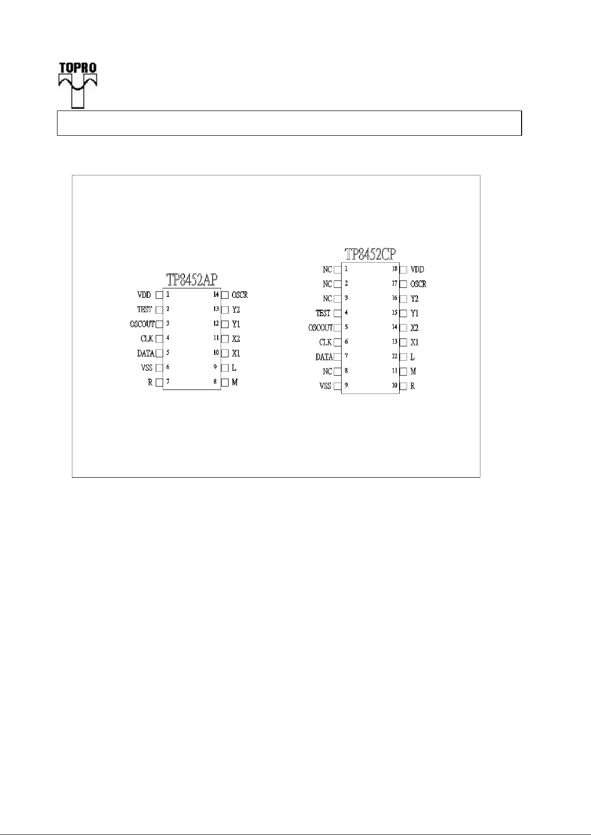
Pin Assignment
Page 3

_______________________________________________________________________________
This specification is subject to be changed without notice.
3
TP8452
PS/2 MOUSE CONTROLLER
Pin Description
1 18 VDD I Power.
2 4 Test If it is connected to VDD or floated,TP8452 will work on normal operation.
While it is connect to GND, TP8452 will enter testing mode, you can use
OSCR to select two types of testing mode.
3 5OSC.OUT O Clock output
4 6CLK I/O 8042 auxiliary port CLK line
5 7DATA I/O 8042 auxiliary port DATA line
6 9VSS Ground.
7 10 R I Three key-switches exert seven different combinations totally.
8 11 M I/O Both key-pressed and key-released signals accompanied with
9 12 L I/O horizontal and vertical state will be sent to the host. The status
of the key-switches will be preserved when RXD is transmitting.
The debounce interval for both key-press and key-release is 12
ms.
In testing mode, L and M are the outputs of motion detector.
Use R key can select the two outputs from X1, X2 or Y1, Y2.
This feature can help manufacture to adjust the phase of four
photo-couples for improving the yield.
10 13 X1 I Four photo-couple signals denote UP, DOWN,LEFT, and RIGHT
11 14 X2 state During the scanning period, as long as the photo-couples
12 15 Y1 change their states, the value of vertical or horizontal counter
13 16 Y2 will accordingly increase or decrease.
14 17 OSCR I If it is connected a 30kohm resistor to ground, TP8452 will employ
a built in RC ckt to generate clock. While it is connected to VDD,and Test
connect to GND, it will enter testing mode, you can observe X/Y input on
L/M pin.
Function Descriptions
(1) PS/2 Mouse Mode
(A) Operating mode
There are four operating modes in PS/2 mouse :
a. Reset Mode :
In this mode a self-test is initiated during power-on or by a Reset command. After reset
signal, PS/2 mouse will send:
(a) Completion code AA & ID code 00.
(b) Set default:
sampling rate: 100 reports/s
non-autospeed
stream mode
4 counts/mm
disable
Pin
Name
I/O
Function
Page 4

_______________________________________________________________________________
This specification is subject to be changed without notice.
4
TP8452
PS/2 MOUSE CONTROLLER
b. Stream Mode:
The maximum rate of transfer is the programmed sampling rate.
Data report is transmitted if
(a) switch is pressed
(b) movement has been detected
c. Remote Mode:
Data is transmitted only in response to a Read Data command.
d. Wrap Mode:
Any byte of data sent by the system, except hex EC ( Reset wrap mode ) or hex FF ( Reset
), is returned by TP8452.
(B) PS/2 Mouse Data Report:
a. In stream mode: A data report is sent at the end of a sample interval.
b. In remote mode: A data report is sent in response to Read Data command.
c. Data report format:
Byte Bit Description
1 0 Left button status; 1 = pressed
1 Right button status; 1 = pressed
2 Middle button status; 1 = pressed
3 Reserved
4 X data sign; 1 = negative
5 Y data sign; 1 = negative
6 X data overflow; 1 = overflow
7 Y data overflow; 1 = overflow
2 0-7 X data ( D0 - D7 )
3 0-7 Y data ( D0 - D7 )
(C) PS/2 mouse Data Transmission:
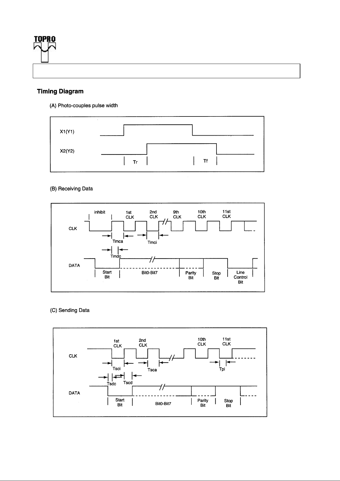
a. TP8452 generates the clocking signal when sending data to and receiving data from the
system.
b. The system requests TP8452 to receive system data output by forcing the DATA line to an
inactive level then allowing CLK line to go to an active level.
c. Data transmission frame:
Bit Function
1 Start bit ( always 0 )
2-9 Data bits ( D0 - D7 )
10 Parity bit ( odd parity )
11 Stop bit ( always 1 )
Page 5

_______________________________________________________________________________
This specification is subject to be changed without notice.
5
TP8452
PS/2 MOUSE CONTROLLER
d. Data Output ( data from TP8452 to system ):
If CLK keep low (inhibit status), data will not transmit.
If CLK raised to high and DATA is low(request-to-send),data is updated.
After receiving data from system, TP8452 will not start transmitting until CLK and DATA
are both high.
If CLK and DATA are both high, the transmission is ready.
DATA is valid prior to the falling edge of CLK and beyond the rising edge of CLK. During
transmission, TP8452 check for line contention by checking for an inactive level on CLK
lasting for no more than 100m sec.
Contention occurs when the system lowers CLK to inhibit TP8452 output after TP8452
has started a transmission. If this occurs before the rising edge of the tenth clock, TP8452
internal store its data in its buffer and returns DATA and CLK to an active level. If the
contention does not occur by the tenth clock, the transmission is completed.
Following a transmission, the system inhibits TP8452 by holding CLK low until it can
service the input or until the system receives a request to send a response from TP8452.
e. Data Input ( from system to TP8452):
System first check if TP8452 is transmitting data. If TP8452 is transmitting, the system
can override the output by forcing CLK to an inactive level prior to the tenth clock. If the
transmission of TP8452 beyond the tenth clock ,the system must receive the data.
If TP8452 is not transmitting or if the system choose to override the output, the system
force CLK to an inactive level for a period of not less than 100u sec while preparing for
output. When the system is ready to output start bit (0), it allows CLK to go to active level.
If request-to-send is detected, TP8452 clocks in 11 bits. Following the tenth clock,TP8452
checks for an active level on the DATA line, and if found, force DATA low , and clock once
more.
If framing error occurs, TP8452 continue to clock until DATA is high, then clocks the line
control bit and request a Resend.
When the system sends out a command or a data that requires a response, the system must
wait for TP8452 to response before sending its next output.
(D) PS/2 Mouse Error Handling:
a. A Resend command ( FE ) following receipt of an invalid input or any input with
incorrect polarity.
b. If two invalid input are received in succession, an error code of hex FC will be sent to
the system.
c. The counter accumulators are cleared after receiving any command except “Resend”.
d. As TP8452 receives a Resend command ( FE ), it transmits its last packet of data.
e. In the stream mode ”Resend” is received by TP8452 following a 3-byte data packet
transmission to the system. TP8452 resend the 3-byte data packet prior to clearing the
counter.
f. A response is sent within 25 ms if
(a) The system requires a response
(b) An error is detected during transmission
g. When a command requiring a response is issued by the system ,another command
should not be issued until either the response is received or 25ms has passed.
Page 6

_______________________________________________________________________________
This specification is subject to be changed without notice.
6
TP8452
PS/2 MOUSE CONTROLLER
(E) PS/2 Mouse Commands Description:
There are 16 valid commands that transmits between the system and TP8452. The “EA”
code is always the first response to any valid input received from the system other than a
Set Wrap Mode or Resend command.
The following table list the commands:
Hex Code Command TP8452 echo code
FF Reset FA,AA,00
FE Resend XX,(XX,XX)
F6 Set Default FA
F5 Disable FA
F4 Enable FA
F3,XX Set Sampling Rate FA,FA
F2 Read Device Type FA,00
F0 Set Remote Mode FA
EE Set Wrap Mode FA
EC Reset Wrap Mode FA
EB Read Data FA,XX,XX,XX
EA Set Stream Mode FA
E9 Status Request FA,XX,XX,XX
E8,XX Set Resolution FA,FA
E7 Set Autospeed FA
E6 Reset Autospeed FA
The following describes valid commands:
a. Reset ( FF )
TP8452 operation:
(a) Complete the reset.
(b) Transmit FA,AA,00 to the system.
(c) Set default:
sampling rate: 100 reports/s
non-autospeed
stream mode
4 counts/mm
disable
b. Resend ( FE )
(a) Any time TP8452 receives an invalid command, it returns a Resend command to
the system.
(b) When TP8452 receives a Resend command, it retransmits its last output. If the
last packet was a Resend command, it transmits the packet just prior to the Resend
command.
Page 7

_______________________________________________________________________________
This specification is subject to be changed without notice.
7
TP8452
PS/2 MOUSE CONTROLLER
(c) In stream mode, if a Resend command is received by TP8452 immediately
following a 3-byte data packet transmission to the system, TP8452 will resend the
3-byte data packet prior to cleaning the count accumulators.
c. Set Default ( F6 )
The command reinitializes all conditions to the power-on defaults.
d. Disable ( F5 )
This command is used in the stream mode to disable transmissions from TP8452.
e. Enable ( F4 )
Enable transmissions, if in stream mode.
f. Set Sampling Rate ( F3,XX )
In the stream mode, this command sets the sampling rate to the value indicated by
byte hex XX, shown as follows:
Second byte XX Sample Rate
0A 10/sec
14 20/sec
28 40/sec
3C 60/sec
50 80/sec
64 100/sec
C8 200/sec
g. Read Device Type ( F2 )
TP8452 always echoes “ FA,00 “ following this command.
h. Set Remote Mode ( F0 )
Data value are reported only in response to a Read Data command.
i. Set Wrap Mode ( EE )
Wrap mode remains until Reset ( FF ) or Reset Wrap Mode( EC ) is received.
j. Reset Wrap Mode ( EC )
TP8452 returns to the previous mode of operation after receiving this command.
k. Read Data ( EB )
This command is executed in either remote or stream mode. The data is transmitted
even if there has been no movement or the button status is unchanged since the last
report. Following a Read Data command, the registers are cleared after a data
transmission.
l. Set Stream Mode ( EA )
This command sets TP8452 in stream mode.
Page 8

_______________________________________________________________________________
This specification is subject to be changed without notice.
8
TP8452
PS/2 MOUSE CONTROLLER
m. Status Request ( E9 )
When this command is issued by the system, TP8452 responds with a 3-byte status
report as follows:
Byte Bit Description
1 0 1 = Right button pressed
1 1 = Middle button pressed
2 1 = Left button pressed
3 Reserved
4 0 = Normal speed, 1 = Autospeed
5 0 = Disabled, 1 = Enabled
6 0 = Stream mode, 1 = Remote mode
7 Reserved
2 0-7 Current resolution setting ( D0 - D7 )
3 0-7 Current sampling rate ( D0 - D7 )
n. Set Resolution ( E8,XX )
TP8452 provides four resolutions selected by the second byte of this command as
follows:
Second Byte XX Resolution
00 1 counts/mm
01 2 counts/mm
02 4 counts/mm
03 8 counts/mm
o. Set Autospeed ( E7 )
At the end of a sample interval in the stream mode, the current X and Y data values
are converted new values. The sign bits are not involved in this conversion.The
conversion is only in stream mode. The relationship between the input and output
count is as follows:
Input Output
0 0
1 1
2 1
3 3
4 6
5 9
N( >=6 ) 2.0*N
p. Reset Autospeed ( E6 )
This command restore normal speed.
Page 9

_______________________________________________________________________________
This specification is subject to be changed without notice.
9
TP8452
PS/2 MOUSE CONTROLLER
(2) Testing Mode
Whenever “Test” pin is connected to GND, the chip will enter buyer's testing mode.
If OSCR (connect to VDD) = “1”¡GThe X direction output signals of comparators will
present to “L” and “M” pin. Pressing "R" key can toggle the output from X direction to Y
direction.
If OSCR (connect to GND) = “0” ¡GThe TP8452’S Internal RC won’ t generate clock. you
can input clock on OSC.OUT pin to let TP8452 work on normal operation.
Page 10

_______________________________________________________________________________
This specification is subject to be changed without notice.
10
TP8452
PS/2 MOUSE CONTROLLER
Min. Ratings Max.
Absolute Maximum Ratings
Supply voltage -0.3 7.5 V
Temperature under bias 0 70
o
C
Storage temperature range -65 150
o
C
Power dissipation - 500
mW
_________________________________________________________________________
DC Electrical Characterisitics (Ta=25 to 70 oC)
Operating voltage V DD 4.5 5.0 5.5
V
Operating current (with load)@33kHz Iop 5.5 mA
OSCR high input voltage Vrh 4 V
X1,X2,Y1,Y2 input reference Current Ipi 45(1v) 1500(5v)
uA
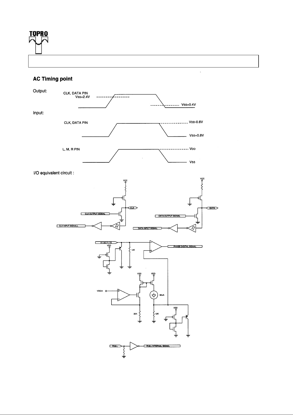
CLK,DATA positive-going threshold voltage Vt+ 3.2 3.8 V
CLK,DATA negaitive-going threshold voltage Vt- 1.2 1.9 V
Low input voltage, other pins Vai 1.5 V
High input voltage , other pins Vaih 3.5 V
L,M,R input current ( pull low resistor, Vin=5V ) Imi 35 45
uA
DATA, CLK input current Idc -0.6 -1.86
mA
( pull up resistor, Vin=0V )
DATA, CLK low output voltage ( Iprl=4mA ) Vprl 0.4 V
OSC IN input leakage current (Vin=5V) Iih 0 1.0 uA
L,M,R input leakage current ( Vin =0V ) Iil -1 1
uA
X1, X2, Y1, Y2 input leakage current (Vin=0V) Iipl -1 1
uA
________________________________________________________________________________
* All voltages in above table are compared with V SS .
* All parameters in above table are tested under V DD =5V.
* CLK & DATA output gates are open drains that connect to pull up resistors.
Parameter
Unit
Parameter
Sym.
Min.
Typ.
Max.
Unit
Page 11

_______________________________________________________________________________
This specification is subject to be changed without notice.
11
TP8452
PS/2 MOUSE CONTROLLER
AC Electrical Characterisitics (Ta=25 to 70 oC)
Oscillating frequency Fosc 33.5-10% 33.5
33.5+10% KHz
Key debounce Tkd 12 ms
Rising edge crossed width (Fosc=35KHz) Tr 14.9 us
Falling edge crossed width (Fosc=35KHz) Tf 14.9 us
Mouse CLK active time Tmca 44.8
us
Mouse CLK inactive time Tmci 44.8
us
Time that mouse sample Tmdc
DATA from CLK rising edge 14.9
us
System CLK active time Tsca 44.8
us
System CLK inactive time Tsci 44.8
us
Time from DATA Tsdc
transition to falling edge of CLK 14.9 us
Time from rising edge of Tscd
CLK to DATA transition 28.6 us
Time to mouse inhibit after the 11th CLK to Tpi 0 50
us
ensure mouse does not start another transmission
________________________________________________________________________________
PS. The AC timings are measured with 33.5 KHz system clock signal.
Parameter
Sym.
Min.
Typ.
Max.
Unit
Page 12
_______________________________________________________________________________
This specification is subject to be changed without notice.
12
TP8452
PS/2 MOUSE CONTROLLER
Page 13
_______________________________________________________________________________
This specification is subject to be changed without notice.
13
TP8452
PS/2 MOUSE CONTROLLER
Page 14
_______________________________________________________________________________
This specification is subject to be changed without notice.
14
TP8452
PS/2 MOUSE CONTROLLER
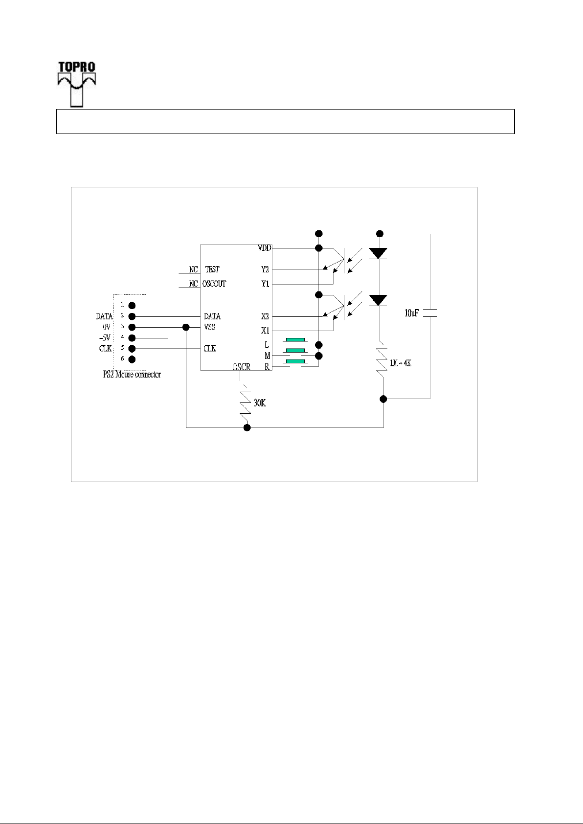
Application Example(A/C):
 Loading...