

Page 1
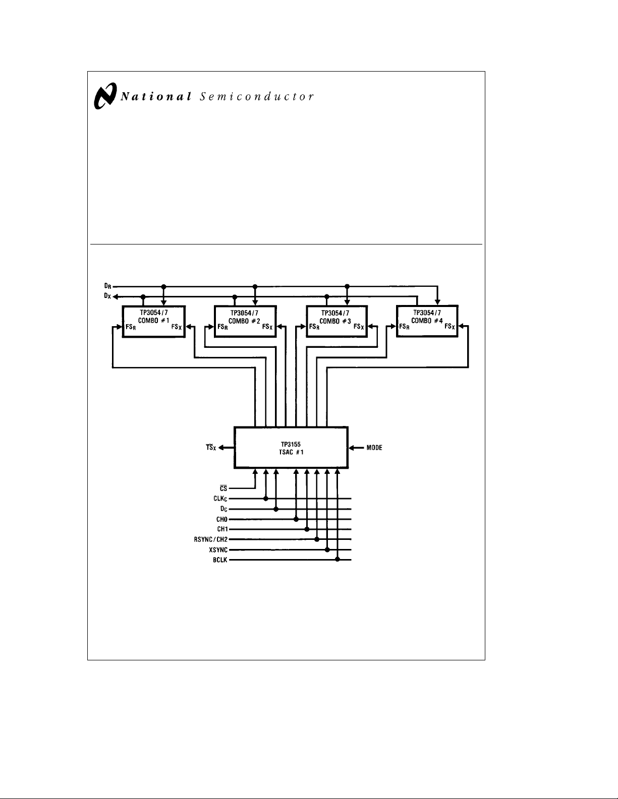
TP3155 Time Slot Assignment Circuit
TP3155 Time Slot Assignment Circuit
September 1993
General Description
The TP3155 is a monolithic CMOS logic circuit designed to
generate transmit and receive frame synchronization pulses
for up to 8 COMBO
TM
CODEC/Filters. Each frame sync
pulse may be independently assigned to a time slot in a
frame of up to 32 time slots. Assignments are controlled by
loading in an 8-bit word via a simple serial interface port.
This control interface is compatible with that used on the
TP3020/TP3021 and 2910/2911 CODECs, enabling an
easy upgrade to COMBO CODEC/Filters to be made.
Typical Application
Features
Y
Controls up to 8 COMBO CODEC/Filters
Y
Independent transmit and receive time slot assignments
Y
8-channel unidirectional mode
Y
Up to 32 time slots per frame
Y
Serial control interface compatible with TP3020/TP3021
CODECs
Y
LS TTL and CMOS compatible inputs
Y
5 mW, 5V operation
TL/H/5118– 1
TRI-STATEÉis a registered trademarks of National Semiconductor Corp.
TM
COMBO
is a trademark of National Semiconductor Corp.
C
1995 National Semiconductor Corporation RRD-B30M115/Printed in U. S. A.
TL/H/5118
Page 2
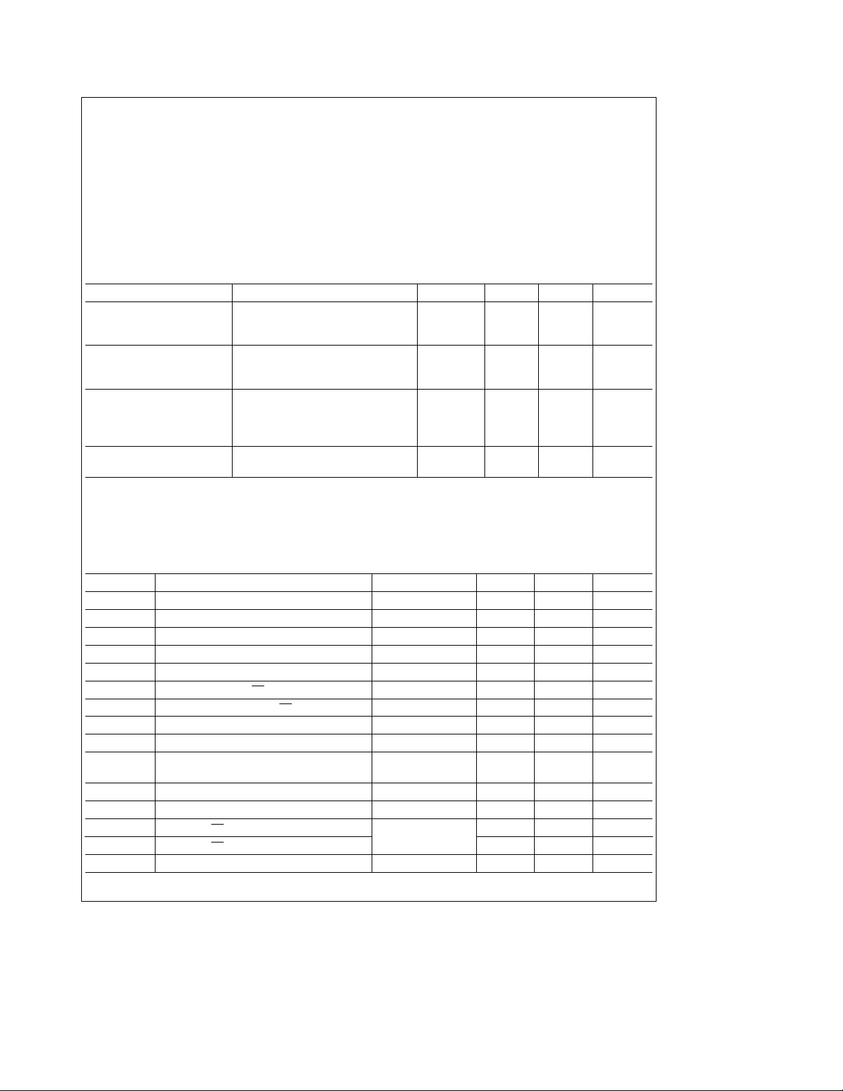
Absolute Maximum Ratings
If Military/Aerospace specified devices are required,
please contact the National Semiconductor Sales
Office/Distributors for availability and specifications.
V
Relative to GND 7V
CC
Voltage at Any Input
or Output V
a
0.3V to GNDb0.3V
CC
Operating Temperature Range
(Ambient)
Storage Temperature Range
(Ambient)
b
25§Ctoa125§C
b
65§Ctoa150§C
Maximum Lead Temperature
(Soldering, 10 seconds) 300
ESD rating to be determined.
C
§
DC Electrical Characteristics
Unless otherwise noted, limits printed in BOLD characters are guaranteed for V
correlation with 100% electrical testing at T
or product design and characterization. Typicals specified at V
e
25§C. All other limits are assured by correlation with other production tests and/
A
CC
e
5.0V, T
A
e
5.0Vg5%; T
CC
e
25§C.
Parameter Conditions Min Typ Max Units
Input Voltage Levels
V
, Logic High 2.0 V
IH
V
, Logic Low 0.7 V
IL
Input Currents
All Inputs Except MODE V
MODE V
k
V
IL
IN
V
IN
0V
IH
e
b
11mA
b
100 mA
k
Output Voltage Levels
V
, Logic High FSXand FSROutputs, I
OH
V
, Logic Low FSXand FSROutputs, I
OL
TS
Output, I
X
e
OL
e
3 mA 2.4 V
OH
e
5 mA 0.4 V
OL
5mA 0.4 V
Power Dissipation BCLKe2.048 MHz, 1 1.5 mA
Operating Current All Outputs Open-Circuit
e
0§Ctoa70§Cby
A
Timing Specifications
Unless otherwise noted, limits printed in BOLD characters are guaranteed for V
correlation with 100% electrical testing at T
or product design and characterization. Typicals specified at V
V
OH
e
2.0V and V
e
0.7V.
OL
e
25§C. All other limits are assured by correlation with other production tests and/
A
CC
e
5.0V, T
A
e
5.0Vg5%, T
CC
e
25§C. All timing parameters are measured at
See Definitions and Timing Conventions section for test methods information.
Symbol Parameter Conditions Min Max Units
t
PC
t
WCH
t
WCL
t
SDC
t
HCD
t
SCC
t
HCC
t
SCHC
t
HCHC
t
DBF
t
HSYNC
t
SSYNC
t
DTL
t
DTH
tRC,t
FC
Period of Clock BCLK, CLK
Width of Clock High BCLK, CLK
Width of Clock Low BCLK, CLK
Set-Up Time from DCto CLK
Hold Time from CLKCto D
Set-Up Time from CS to CLK
C
C
C
C
C
C
480 ns
160 ns
160 ns
50 ns
50 ns
30 ns
Hold Time from CLKCto CS 100 ns
Set-Up Time from Channel Select to CLK
Hold Time from Channel Select to CLK
Delay Time from BCLK Low to FS
High or Low
0–3 C
X/R
C
C
e
50 pF 100 ns
L
50 ns
50 ns
Hold Time from BCLK to Frame Sync 50 ns
Set-Up Time from Frame Sync to BCLK 100 ns
e
50 pF
Delay to TSXLow
Delay to TSXHigh
Rise and Fall Time of Clock BCLK, CLK
C
L
e
R
1k to V
L
CC
C
30 140 ns
e
0§Ctoa70§Cby
A
140 ns
50 ns
2
Page 3
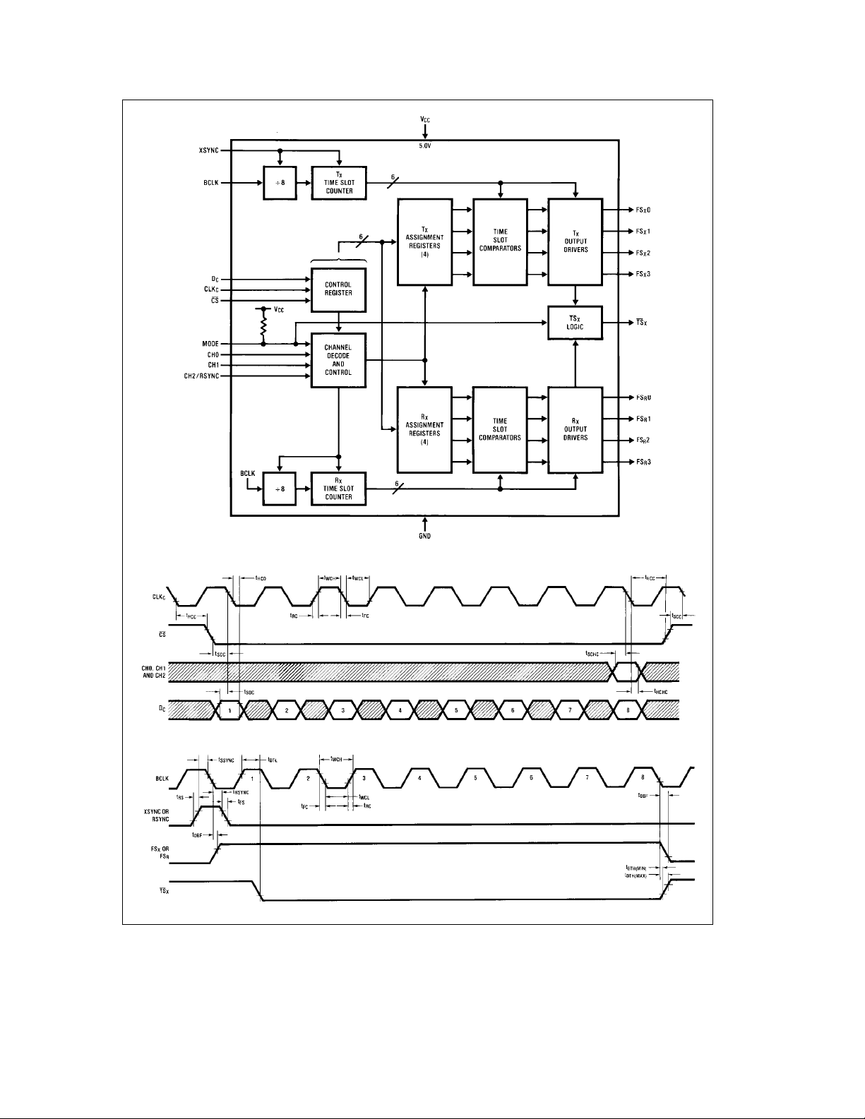
Block Diagram
Timing Diagrams
TL/H/5118– 2
Control Interface
TL/H/5118– 3
Output
TL/H/5118– 4
3
Page 4
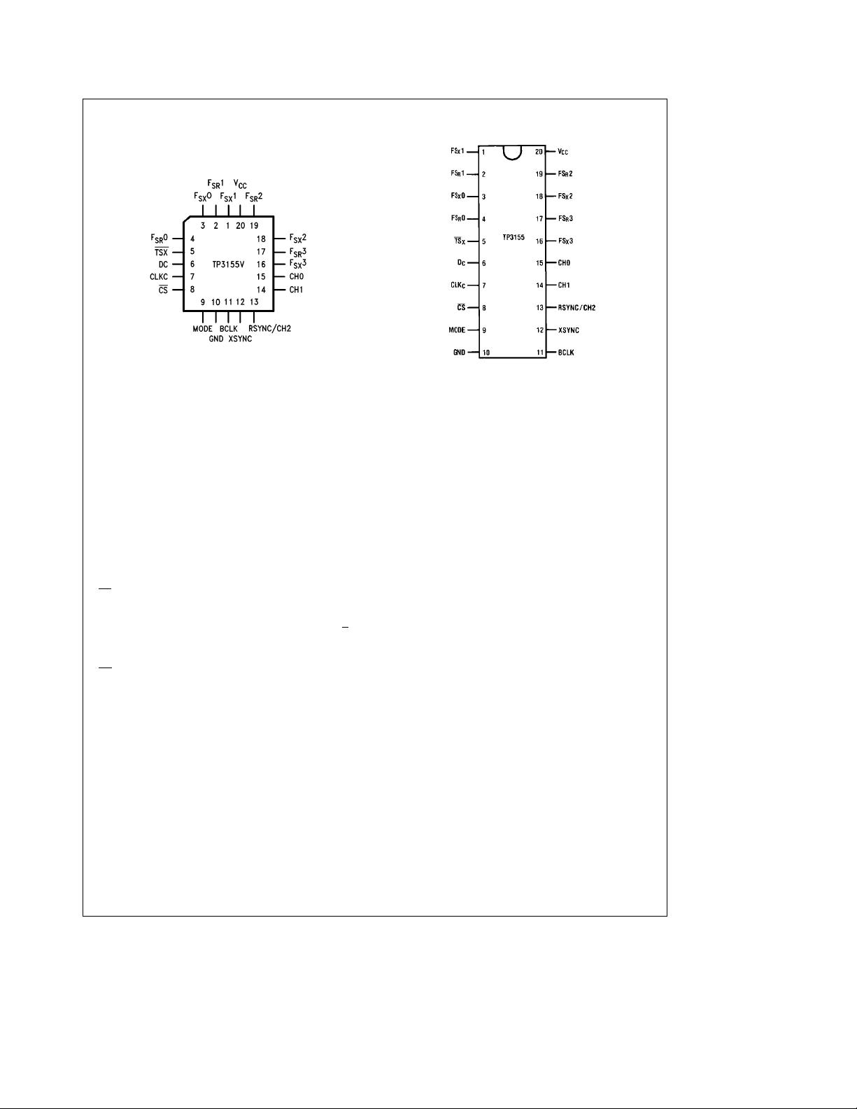
Connection Diagrams
Plastic Chip Carrier (PCC) Package
TL/H/5118– 5
Order Number TP3155V
See NS Package Number V20A
Pin Descriptions
Symbol Description
FSX1 A conventional CMOS frame sync output
FS
1 A conventional CMOS frame sync output
R
FS
0 A transmit frame sync output similar to pin 1.
X
FSR0 A receive frame sync output similar to pin 2.
TS
X
D
C
CLK
C
CS The active-low chip select for the control in-
MODE The mode select input. When left open-circuit
GND The 0V ground connection to the device.
which is normally low, and goes active-high
for 8 cycles of BCLK when a valid transmit
time slot assignment is made.
which is normally low, and goes active-high
for 8 cycles of BCLK when a valid receive
time slot assignment is made.
An open-drain N-channel output which is normally high impedance but pulls low during any
active transmit time slot.
The input for an 8-bit serial control word. X is
the first bit clocked in.
The clock input for the control interface.
terface.
or connected to V
when connected to GND, mode 2 is selected.
, mode 1 is selected, and
CC
Dual-In-Line Package
Top View
TL/H/5118– 6
Order Number TP3155N
See NS Package Number N20A
Symbol Description
BCLK The bit clock input, which should run at the
same rate as that for the COMBO CODEC/
Filter COMBO.
XSYNC The transmit TS0 sync pulse input. Must be
synchronous with BCLK.
RSYNC/CH2 The function of this input is determined by the
MODE input (pin 9). In mode 1 this is the receive TS0 sync pulse, RSYNC, which must be
synchronous with BCLK. In mode 2 this is the
CH2 input for the MSB of the channel select
word.
CH1 The input for the next significant bit of the
channel select word.
CH0 The input for the LSB of the channel select
word, which defines the frame sync output affected by the following control word.
FS
3 A transmit frame sync output similar to pin 1.
X
3 A receive frame sync output similar to pin 2.
FS
R
FSX2 A transmit frame sync output similar to pin 1.
FSR2 A receive frame sync output similar to pin 2.
V
CC
The positive supply to the device. 5Vg5%.
4
Page 5
Functional Description
OPERATING MODES
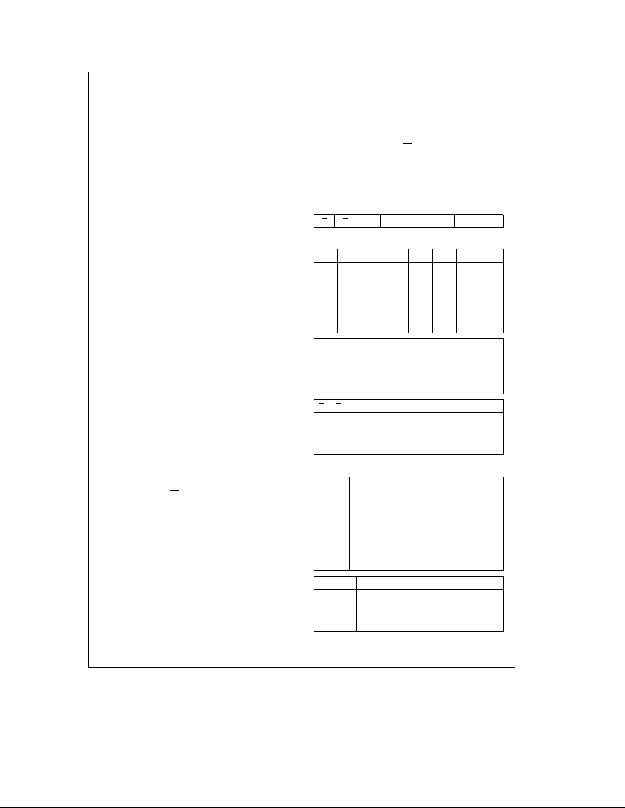
The TP3155 control interface requires an 8-bit serial control
word which is compatible with the TP3020/TP3021 and
2910/2911 CODECs. Two bits, X
two groups of frame sync outputs, FS
FS
3, is affected by the control word, and a 6-bit assign-
R
ment field specifies the selected time slot, from 0 to 31. A
frame sync output is active-high for one time slot, which is
always 8 cycles of BCLK. A frame may consist of any number of time slots up to 32. If a timeslot is assigned which is
beyond the number of time slots in a frame, the FS
output to which it was assigned will remain inactive.
Two modes of operation are available. Mode 1 is for systems requiring different time slot assignments for the transmit and receive direction of each channel. Mode 1 is selected by leaving pin 9 (MODE) open-circuit or connecting it to
V
. In this case, Pin 13 is the RSYNC input which defines
CC
the start of each receive frame, and the four outputs,
FS
0–FSR3, are assigned with respect to RSYNC. The
R
XSYNC input defines the start of each transmit frame and
outputs FS
XSYNC may have any phase relationship with RSYNC. In-
0–FSX3 are assigned with respect to XSYNC.
X
puts CH0 and CH1 select the channel, from 0 to 3 (see
Table Ia).
Mode 2 provides the option of assigning all 8 frame sync
outputs with respect to the XSYNC input. Mode 2 is selected by connecting pin 9 (MODE) to GND. This makes the
TP3155 TSAC useful for either an 8-channel undirectional
controller or for systems in which the transmit and receive
directions of each channel are always assigned to the same
time slot as the other, i.e., the FS
COMBO CODEC/Filter are hard-wired together. In this
case, logical selection of the channel to be assigned is
made via inputs CH0, CH1 and CH2 (see Table Ib).
POWER-UP INITIALIZATION
During power-up, all frame sync outputs, FS
FS
0–FSR3, are inhibited and held low. No outputs will go
R
active until a valid time slot assignment is made.
LOADING CONTROL DATA
During the loading of control data, the binary code for the
selected channel must be set on inputs CH0 and CH1 (and
CH2 in mode 2), see Tables Ia and Ib.
Control data is clocked into the D
edges of CLK
while CS is low.
C
A new time slot assignment is transferred to the selected
assignment register on the high going transition of CS
new assignment is re-synchronized to the system clock
such that the new FS output pulses will start at the next
complete valid time slot after the rising edge of CS
TIME SLOT COUNTER OPERATION
At the start of TS0 of each transmit frame, defined by the
first falling edge of BCLK after XSYNC goes high, the transmit time slot counter is reset to 000000 and begins to increment once every 8 cycles of BCLK. Each count is compared
with the 4 transmit assignment registers and, on finding a
match, a frame sync pulse is generated at that FS
Similarly, the first falling edge of BCLK after RSYNC goes
high defines the start of receive TS0, and outputs
FS
0–FSR3 are generated with respect to TS0 when the
R
receive time slot counter matches the appropriate receive
assignment register.
and R, define which of the
0toFSX3orFSR0to
X
or FS
X
and FSRinputs on the
X
0–FSX3 and
X
input on the falling
C
. The
.
output.
X
TS
OUTPUT
X
In mode 1 (separate transmit and receive assignments), this
output pulls low whenever any FS
generated. In mode 2, this output pulls low whenever any
FS
or FSRoutput is being generated. At all other times it is
X
open-circuit, allowing the TS
TSACS to be wire-ANDed together with a common pull-up
output pulse is being
X
outputs of a number of
X
resistor. This signal can be used to control the TRI-STATE
enable input of a line driver to buffer the transmit PCM bus
from the CODEC/Filters to the backplane.
R
TABLE Ia. Control Mode 1
(TP3020/TP3021 Compatible)
X R T5 T4 T3 T2 T1 T0
X is the first bit clocked into the DCinput.
Control Data Format
T5 T4 T3 T2 T1 T0 Time Slot
000000 0
000001 1
000010 2
011110 30
011111 31
1 X X X X X (Note 1)
CH1 CH0 Channel Selected
0 0 Assign to FSx0 and/or FSR0
0 1 Assign to FS
1 0 Assign to FS
1 1 Assign to FS
X R Action
0 0 Assign time slot to both selected FSXand FS
0 1 Assign time slot to selected FSXonly
1 0 Assign time slot to selected FS
1 1 Disable both selected FS
and FS
X
TABLE Ib. Control Mode 2
CH2 CH1 CH0 Channel Selected
0 0 0 Assign to FSX0
0 0 1 Assign to FS
0 1 0 Assign to FS
0 1 1 Assign to FS
1 0 0 Assign to FS
1 0 1 Assign to FS
1 1 0 Assign to FSR2
1 1 1 Assign to FS
X R Action
00
0 1 Assign time slot to selected output
10
(
1 1 Disable selected output
Note 1: When T5e1, then the appropriate FSXor FSRoutput is inactive.
1 and/or FSR1
x
2 and/or FSR2
x
3 and/or FSR3
x
only
R
R
:
1
X
2
X
3
X
0
R
1
R
3
R
É
R
5
Page 6

Definitions and Timing Conventions
DEFINITIONS
V
IH
V
IL
V
OH
V
OL
Threshold Region The threshold region is the range of in-
Valid Signal A signal is Valid if it is in one of the valid
Invalid Signal A signal is Invalid if it is not in a valid
TIMING CONVENTIONS
For the purposes of this timing specification the following
conventions apply:
Input Signals All input signals may be characterized
Period The period of clock signal is designated
VIHis the d.c. input level above which
an input level is guaranteed to appear
as a logical one. This parameter is to
be measured by performing a functional test at reduced clock speeds and
nominal timing, (i.e. not minimum setup
and hold times or output strobes), with
the high level of all driving signals set
to V
and maximum supply voltages
IH
applied to the device.
VILis the d.c. input level below which
an input level is guaranteed to appear
as a logical zero to the device. This parameter is measured in the same manner as V
levels set to V
voltages applied to the device.
but with all driving signal low
IH
and minimum supply
IL
VOHis the minimum d.c. output level to
which an output placed in a logical one
state will converge when loaded at the
maximum specified load current.
VOLis the maximum d.c. output level to
which an output placed in a logical zero
state will converge when loaded at the
maximum specified load current.
put voltages between V
logic states, (i.e. above V
V
). In timing specifications, a signal is
IL
deemed valid at the instant it enters a
and VIH.
IL
IH
or below
valid state.
logic state, i.e. when it is in the threshold region between V
ing specifications, a signal is deemed
and VIH. In tim-
IL
Invalid at the instant it enters the
threshold region.
e
as: V
L
k
t
10ns.
F
as t
where xx represents the mne-
Pxx
monic of the clock signal being speci-
0.4V, V
e
H
2.4V, t
k
10 ns,
R
fied.
Rise Time Rise times are designated as t
where yy represents a mnemonic of the
Ryy
signal whose rise time is being specified. t
is measured from VILto VIH.
Fall Time Fall times are designated as t
Ryy
where yy represents a mnemonic of the
Fyy
signal whose fall time is being specified. t
is measured from VIHto VIL.
Fyy
Pulse Width High The high pulse width is designated as
t
, where zz represents the mne-
WzzH
monic of the input or output signal
whose pulse width is being specified.
High pulse widths are measured from
V
to VIH.
IH
Pulse Width Low The low pulse width is designated as
t
, where zz represents the mne-
WzzL
monic of the input or output signal
whose pulse width is being specified.
Low pulse widths are measured from
V
to VIL.
Setup Time Setup times are designated as t
IL
where ww represents the mnemonic of
Swwxx
the input signal whose setup time is being specified relative to a clock or
strobe input represented by mnemonic
xx. Setup times are measured from the
ww Valid to xx Invalid.
Hold Time Hold times are designated as t
where ww represents the mnemonic of
Hxxww
the input signal whose hold time is being specified relative to a clock or
strobe input represented by mnemonic
xx. Hold times are measured from xx
Valid to ww Invalid.
Delay Time Delay times are designated as
t
Dxxyy
mnemonic of the input reference signal
, where xx represents the
[
]
L
lHl
and yy represents the mnemonic of the
output signal whose timing is being
specified relative to xx. The mnemonic
may optionally be terminated by an H
or L to specify the high going or low
going transition of the output signal.
Maximum delay times are measured
from xx Valid to yy Valid. Minimum delay times are measured from xx Valid to
yy Invalid. This parameter is tested under the load conditions specified in the
Conditions column of the Timing Specifications section of this data sheet.
,
,
,
,
6
Page 7
Applications Information
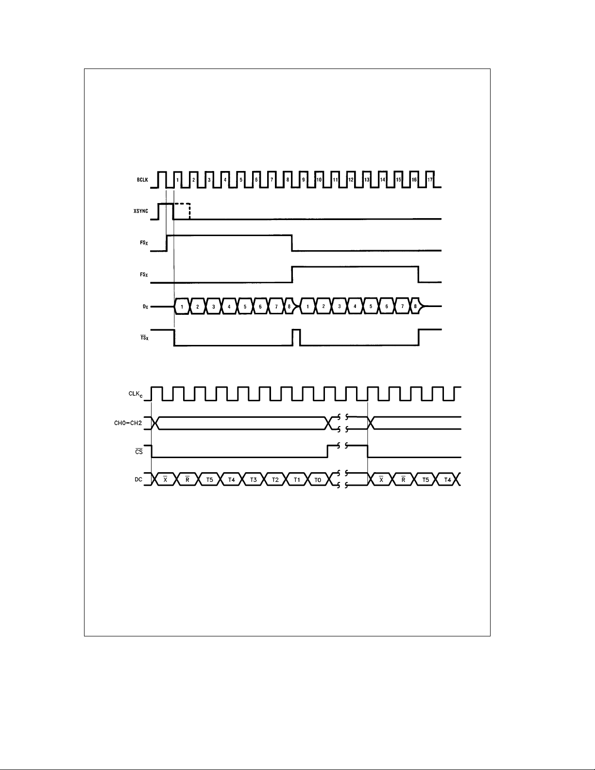
A combination of the TP3155 TSAC and any CODEC/Filter
COMBO from the TP3052/3/4/7 or TP3064/7 series will
result in data timing as shown in
output pulse goes high before BCLK goes high, the Dxoutput of the combo remains in the TRI-STATE mode until both
are high. The eight bit period is shortened to prevent a bus
clash, just as it is on the TP3020/1 CODECs.
Figure 1
. Although the FS
Alternatively, eight full-length bits can be obtained by inverting the BCLK to the combo devices, thereby aligning rising
edges of BCLK and FS
x
Figure 2
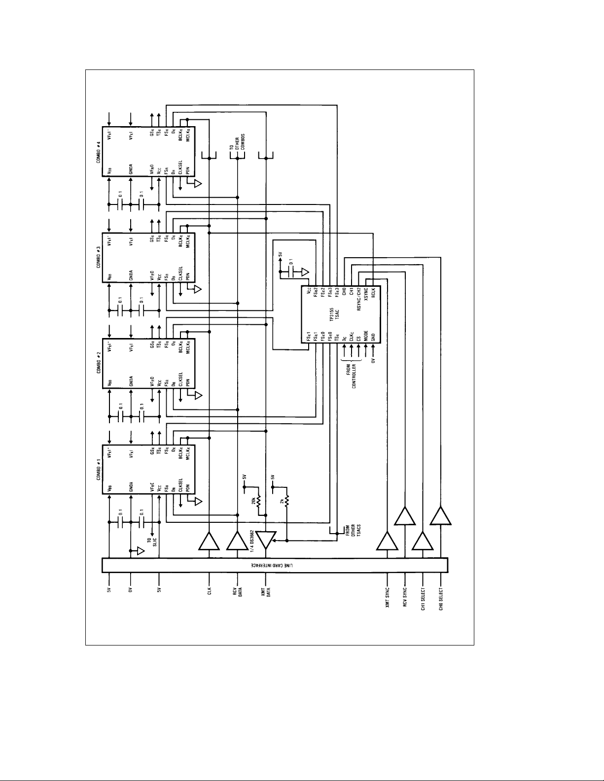
Figure 3
shows typical timing for the control data interface.
shows the digital interconnections of a typical line
X/R
.
card application.
FIGURE 1. Transmit Data Timing
FIGURE 2. Control Data Timing
TL/H/5118– 7
TL/H/5118– 8
7
Page 8
Application Information (Continued)
TL/H/5118– 9
FIGURE 3. Digital Interconnections on a Typical Synchronous Line Card
8
Page 9
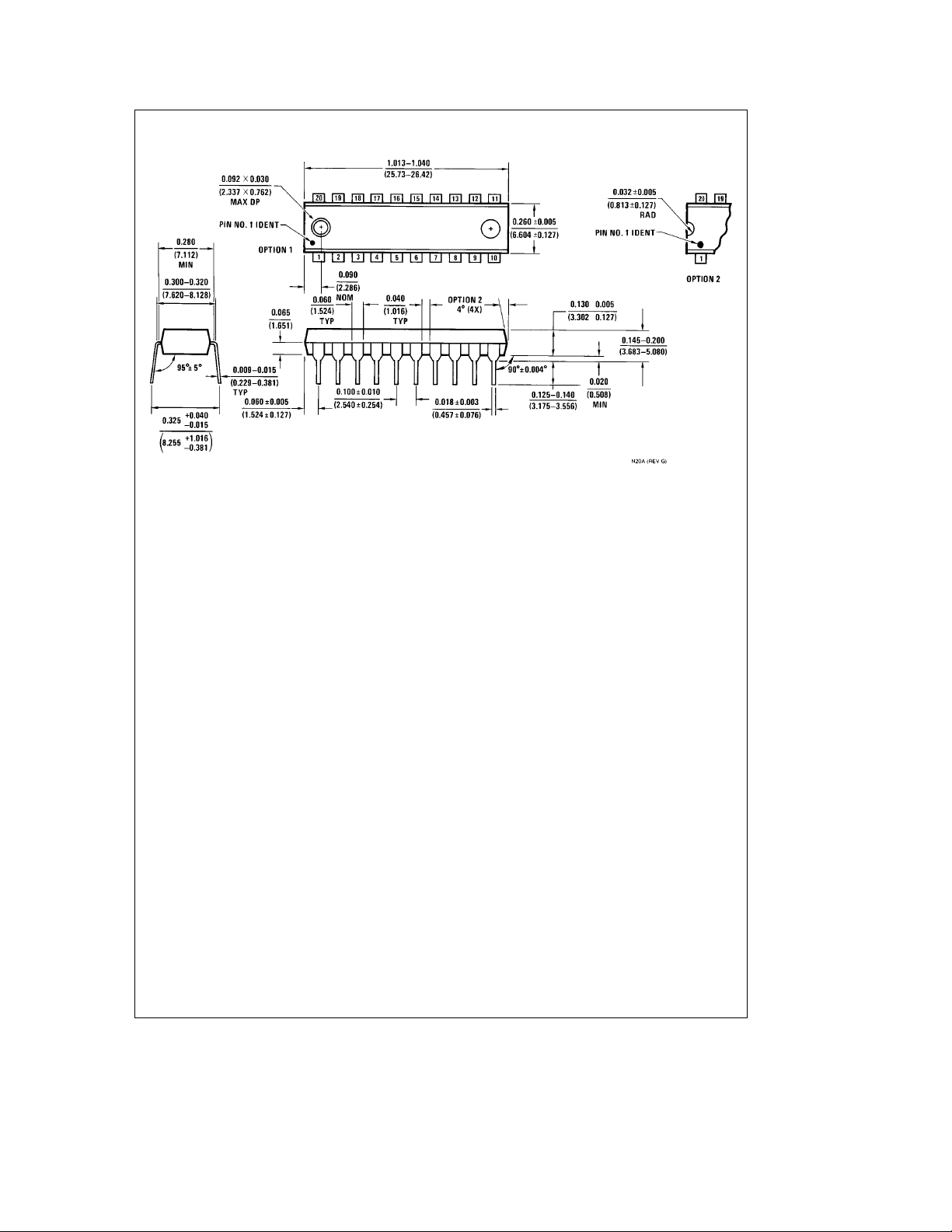
Physical Dimensions inches (millimeters)
Molded Dual-In-Line Package (N)
Order Number TP3155N
NS Package Number N20A
9
Page 10
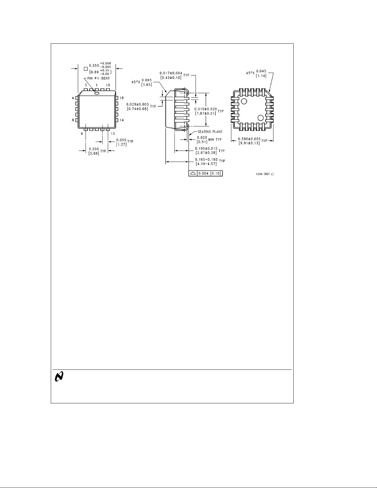
Physical Dimensions inches (millimeters) (Continued) Lit.
Ý
113982
TP3155 Time Slot Assignment Circuit
Plastic Chip Carrier Package (V)
Order Number TP3155V
NS Package Number V20A
LIFE SUPPORT POLICY
NATIONAL’S PRODUCTS ARE NOT AUTHORIZED FOR USE AS CRITICAL COMPONENTS IN LIFE SUPPORT
DEVICES OR SYSTEMS WITHOUT THE EXPRESS WRITTEN APPROVAL OF THE PRESIDENT OF NATIONAL
SEMICONDUCTOR CORPORATION. As used herein:
1. Life support devices or systems are devices or 2. A critical component is any component of a life
systems which, (a) are intended for surgical implant support device or system whose failure to perform can
into the body, or (b) support or sustain life, and whose be reasonably expected to cause the failure of the life
failure to perform, when properly used in accordance support device or system, or to affect its safety or
with instructions for use provided in the labeling, can effectiveness.
be reasonably expected to result in a significant injury
to the user.
National Semiconductor National Semiconductor National Semiconductor National Semiconductor
Corporation Europe Hong Kong Ltd. Japan Ltd.
1111 West Bardin Road Fax: (
Arlington, TX 76017 Email: [email protected] Ocean Centre, 5 Canton Rd. Fax: 81-043-299-2408
Tel: 1(800) 272-9959 Deutsch Tel: (
Fax: 1(800) 737-7018 English Tel: (
National does not assume any responsibility for use of any circuitry described, no circuit patent licenses are implied and National reserves the right at any time without notice to change said circuitry and specifications.
Fran3ais Tel: (
Italiano Tel: (
a
49) 0-180-530 85 86 13th Floor, Straight Block, Tel: 81-043-299-2309
a
49) 0-180-530 85 85 Tsimshatsui, Kowloon
a
49) 0-180-532 78 32 Hong Kong
a
49) 0-180-532 93 58 Tel: (852) 2737-1600
a
49) 0-180-534 16 80 Fax: (852) 2736-9960
 Loading...