

Page 1

FCC ID:NUSTMW1052
Annex P User’s Manual (Draft)
2.4GHz Wireless LAN Mini-PCI Card Model:TMW1052
User’s Manual
(Draft)
TOKO INC.
Page 1 of 4
Page 2

1. FCC Compliance
This device complies with Part 15 of the FCC Rules. Operation is subject to following two conditions:
(1) this device may not cause harmful interference. and (2) this device must accept any interference
received, including interference that may cause undesired operation.
This equipment has been tested and found to comply with the limits for a Class B Personal Computer and
Peripheral, pursuant to Part 15 of the FCC Rules. These limits are designed to provide reasonable protection
against harmful interference in a residential installation. This equipment generates, uses and can radiate
radio frequency energy and, if not installed and used in accordance with the instructions, may cause harmful
interference to radio communications.
However, there is no guarantee that interference will not occur in a particular installation. If this equipment
dose cause harmful interference to radio or television reception, which can be determined by turning the
equipment off and on, the user is encouraged to try to correct the interference by one or more of the following
measures:
- Reorient or relocate the receiving antenna.
- Increase the separation between the equipment and receiver.
- Connect the equipment into an outlet on a circuit different from that to which the receiver is connected.
- Consult the dealer or an experienced radio/TV technician for help.
This equipment has been tested to comply with the limits for a Class B personal computer and peripheral,
pursuant to Subpart B of Part 15 of FCC Rules. Only peripherals(computer input/output devices, terminals,
printers, etc.) certified (DoC) or verified to comply with Class B limits may be attached to this equipment.
Operation with non-certified (DoC) or non-verified personal computer and/or peripherals is likely to result in
Interference to radio and TV reception. The connection of a unshielded equipment interface cable to this
Equipment will invalidate the FCC Certification of this device and may cause interference levels which
Exceed the limits established by FCC for equipment.
You are cautioned that changes or modifications not expressly approved by the party responsible for
compliance could void your authority to operate the equipment.
Thisdeviceanditsantennamustnotbeco‑locatedoroperatinginconjunctionwithanyotherantenna
ortransmitter.
Page 2 of 4
Page 3
3. Feature
• Support for 11, 5.5, 2 and 1 Megabit Per Second (Mbps) Data Rates.
• Supports the lEEE 802.11 Direct Sequence Specification.
• Driver Supports Microsoft® Windows® 98, 2000, Me, Xp. ※1
• Advanced RAKE Receiver Design with Decision Feedback Equalizer.
※
1
Microsoft® and Windows® and Windows NT® are registered trademarks of Microsoft Corporation.
4. Specifications
・Absolute Maximum Ratings
Supply Voltage. . . . . . . . . . . . . . -0.3V to 4.0V (Max)
Storage Temperature ※2 . . . . ... . . . . – 10℃ to 60℃
※2 All temperature references refer to ambient conditions.
・Operating Conditions
Temperature Range . . . . . . . . . . . . . . 0℃ TA 55℃
Supply Voltage Range . . . . . . . . . . . . 3.0V to 3.6V
Caution: These are the absolute maximum ratings for the Mini-PCI product.
Exceeding these limits could cause permanent damage to the card.
・Electrical Specifications
Test Conditions: Supply Voltage (VCC ) = 3.3V, Ambient Temperature (TA) = 25℃, Unless Otherwise Specified
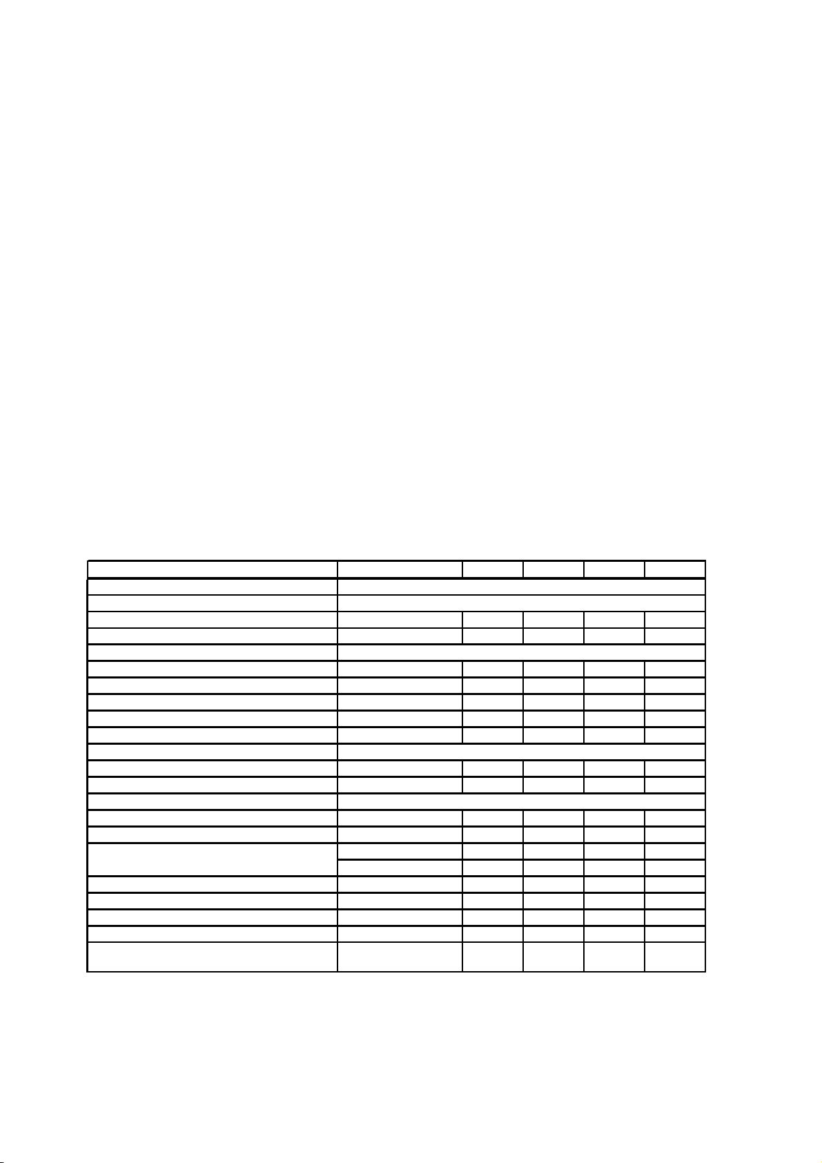
MECHANICAL Mini-PCI Card Type Ⅲ
CURRENT CONSUMPTION
Continuous Transmit Mode - 325 380 mA
Continuous Receive Mode
Mini-PCI LOGIC LEVELS
Input HIGH Voltage
Input LOW Voltage
Output HIGH Voltage
Output LOW Voltage
Input Leakage Current
Mini-PCI LOADING CAPACITANCE
Input Capacitance - 5 10 pF
Output Capacitance - 5 10 pF
RF SYSTEM SPECIFICATIONS
Center Frequency Range 2412 - 2462 MHz
Transmitter Power Output-15.7mW
Receive Sensitivity
Maximum Receive Level
Image Rejection
IF Rejection
Adjacent Channel Rejection
Data Rate (Physical Layer) -
PARAMETER TEST CONDITIONS MIN TYP MAX UNITS
Receiving Valid Packets
Vcc=Max,Min
Vcc=Min,Max
Iol=2mA,Vcc=Min
Iol=2mA,Vcc=Min
Vcc=Max,Input=0V or Vcc
5.5Mbps, 8% PER
11Mbps, 8% PER
PER <8%
PER 8%
PER 8%
PER <8%
- 200 225 mA
0.7Vcc - - V
- - 0.3Vcc V
0.9Vcc 2.6 - V
- 0.05 0.1Vcc V
0.1 1.0 μA
- -87 - dBm
- -83 - dBm
-3 +3 - dBm
-NA ZIF- dB
-NA ZIF- dB
-40-dB
1, 2,
5.5,11
-Mbps
Page 3 of 4
Page 4

5. Installation
① The following work is done with card(TMW1052) not inserted in PC.
② Setup.exe in Driver CD ROM is executed.
③ Please input the key to setting utility according to the instruction displayed on the screen.
④ The message of the purport by which PC is rebooted is displayed.
Please reboot PC.
⑤ Please insert card(TMW1052) in PC.
⑥ The installation of the driver is automatically completed.
⑦ The networks and communication channel and the communication mode are set.
⑧ Please set the network according to the manual of OS.
⑨ The communication mode and the communication channel are set by utility in the task tray.
The communication mode is set in "Adhoc". The communication channel is made the same
as the other party of the communication set . Channels which can be set are from 1 to 11.
Page 4 of 4
 Loading...