

Page 1
2.4GHz
Wireless LAN
Access Point
Read This First
PCWA-A220
Sony Corporation 2002 Printed in Japan
4-665-781-11(1)
WARNING
To prevent fire or shock hazard, do not
expose the unit to rain or moisture.
To avoid electrical shock, do not open the
cabinet. Refer servicing to qualified
personnel only.
Owner’s Record
The model and serial numbers are located on the
bottom of the product. Record the serial number in
the space provided below. Refer to them whenever
you call upon your Sony dealer regarding this
product.
Model No. PCWA-A220
Serial No.______________
CAUTION
You are cautioned that any changes or
modifications not expressly approved in this
manual could void your warranty.
FCC ID: XXXXXXX
Exposure to Radio Frequency Radiation.
The radiated output power of the Wireless LAN
Access Point is far below the FCC radio frequency
exposure limits.
Nevertheless, the Wireless LAN Access Point shall
be used in such a manner that the potential for
human contact during normal operation is
minimized.
FCC Radio-Frequency Exposure Statement
This equipment generates and radiates radiofrequency energy. In order to comply with FCC
radio-frequency radiation exposure guidelines for
an uncontrolled environment, this equipment has to
be installed and operated while maintaining a
minimum body to antenna distance of 20 cm. Based
on continuous exposure of 30 minutes.
Users are not permitted to make changes or modify
the system in any way.
NOTE:
This equipment has been tested and found to
comply with the limits for a Class B digital device,
pursuant to Part 15 of the FCC Rules. These limits
are designed to provide reasonable protection
against harmful interference in a residential
installation. This equipment generates, uses, and
can radiate radio frequency energy and, if not
installed and used in accordance with the
instructions, may cause harmful interference to
radio or communications. However, there is no
guarantee that interference will not occur in a
particular installation. If this equipment does cause
harmful interference to television reception, which
can be determined by turning the equipment off and
on, you are encouraged to try to correct the
interference by one or more of the following
measures:
– Reorient or relocate the receiving antenna.
– Increase the separation between the equipment
and receiver.
– Connect the equipment into an outlet on a
circuit different from that to which the receiver
is connected.
– Consult the dealer or an experienced radio/TV
technician for help.
You are cautioned that any changes or modifications
not expressly approved in this manual could void
your authority to operate this equipment.
If you have questions about this product, call the
Sony Customer Information Center at
1-877-760-7669; or write to the Sony Customer
Information Center at 12451 Gateway Boulevard,
Fort Myers, FL 33913. The number below is for
FCC-related matters only.
This device must not be co-located or operating in
conjunction with any other antenna or transmitter.
Declaration of Conformity
Trade Name: Sony
Model No: PCWA-A220
Responsible Party: Sony Electronics Inc.
Address: 680 Kinderkamack Road,
Oradell, NJ 07649 USA
Telephone: 201-930-6972
This phone number is for FCC-related matters
only.
This device complies with part 15 of the FCC
Rules.
Operation is subject to the following two
conditions:
(1) This device may not cause harmful
interference, and
(2) this device must accept any interference
received, including interference that may cause
undesired operation.
The supplied interface cable must be used with the
equipment in order to comply with the limits for a
digital device pursuant to Subpart B of Part 15 of
FCC Rules.
The socket outlet shall be installed near the
equipment and shall be easily accessible.
NOTE:
The power outlet should be installed near the
equipment and should be easily accessible.
Safety Information
WARNING
• Opening the unit, for whatever reason, could lead
to damages that are not covered by the warranty.
• Do not touch the device or accessories during
thunder storms. Electrical shock could result.
• This device is made for use in the USA only.
• For indoor use only.
• Do not use this equipment on hospital premises.
Doing so may cause medical devices to
malfunction.
• If using the equipment near a pacemaker, make
sure it is at least 9 inches (22 cm) away from the
pacemaker.
• Do not use this equipment in an aircraft, as doing
so could cause the aircraft's equipment to
malfunction.
• While using the Access Point, do not cover it or
turn it on its side. Do not cover the Access Point
with objects such as magazines or newspapers or
use it in confined, enclosed places, such as the
spaces between walls and furniture. Further, do
not turn the Access Point on its side while using
it. Either situation could cause heat to build up
inside the Access Point, leading to overheating
and possible fire.
• Carefully place the Ethernet cable, AC adapter,
and other wiring. Personal injury or damage to
the Access Point could result from people
tripping over the Ethernet cable, AC adapter, or
power cord. Protect wiring by locating it in
places where people do not walk.
• Do not swing the AC adapter. Injury could result
if the adapter strikes a person or fragile material,
such as glass.
• Keep the Access Point out of the reach of
children. Unforeseeable injury could result from
swallowing loose parts, etc.
• Place the Access Point on a stable surface. Do
not place the Access Point on wobbly or tilted
surfaces. Tipping or falling could result in injury.
• When using wall mounting, make sure that the
wall is strong enough to support the Access
Point. The Access Point could fall if the wall is
not strong enough, leading to unforeseeable
accidents. Further, be careful not to drop the unit
or the tools used for mounting it. Doing so could
result in unforeseeable accidents.
• Avoid locations that are directly exposed to
sunlight or heaters.
• Internal overheating could result in fire or
damage to the unit.
• Make sure connectors are properly connected.
– Do not insert any metallic objects inside the
connectors. Short-circuiting the pins could cause
fire or damage to the unit.
– Be careful to insert connectors squarely. Crooked
insertion could cause pins to short-circuit,
possibly causing fire or damage to the unit.
• Use only the supplied AC adapter with your Sony
Wireless LAN Access Point. To disconnect your
Wireless LAN Access Point from the power
supply, unplug the AC adapter.
For the customers in Canada
• This class B digital apparatus complies with
Canadian ICES-003.
• Operation is subject to the following two
conditions; (1) this device may not cause
interference, and (2) this device must accept any
interference, including interference that may
cause undesired operation of the device.
• To prevent radio interference to the licensed
service, this device is intended to be operated
indoors and away from windows to provide
maximum shielding. Equipment (or its transmit
antenna) that is installed outdoors is subject to
licensing.
• The term “IC” before the equipment certification
number only signifies that Industry Canada
technical specifications were met.
Pour les utilisateurs au Canada
• Cet appareil numérique de la classe B est
conforme à la norme NMB-003 du Canada.
• L'utilisation de ce dispositif est autorisée
seulement aux conditions suivantes : (1) il ne doit
pas produire de brouillage et (2) l'utilisateur du
dispositif doit être prêt à accepter tout brouillage
radioélectrique reçu, même si ce brouillage est
susceptible de compromettre le fonctionnement
du dispositif.
• Pour empêcher que cet appareil cause du
brouillage au service faisant l'objet d'une licence,
il doit être utilisé à l’intérieur et devrait être placé
loin des fenêtres afin de fournir un écran de
blindage maximal. Si le matériel (ou son antenne
d’émission) est installé à l’extérieur, il doit faire
l'objet d'une licence.
• Le terme “IC” avant le muméro d’homologation
ne signifie seulement que les normes d’Industrie
du Canada ont été respectées.
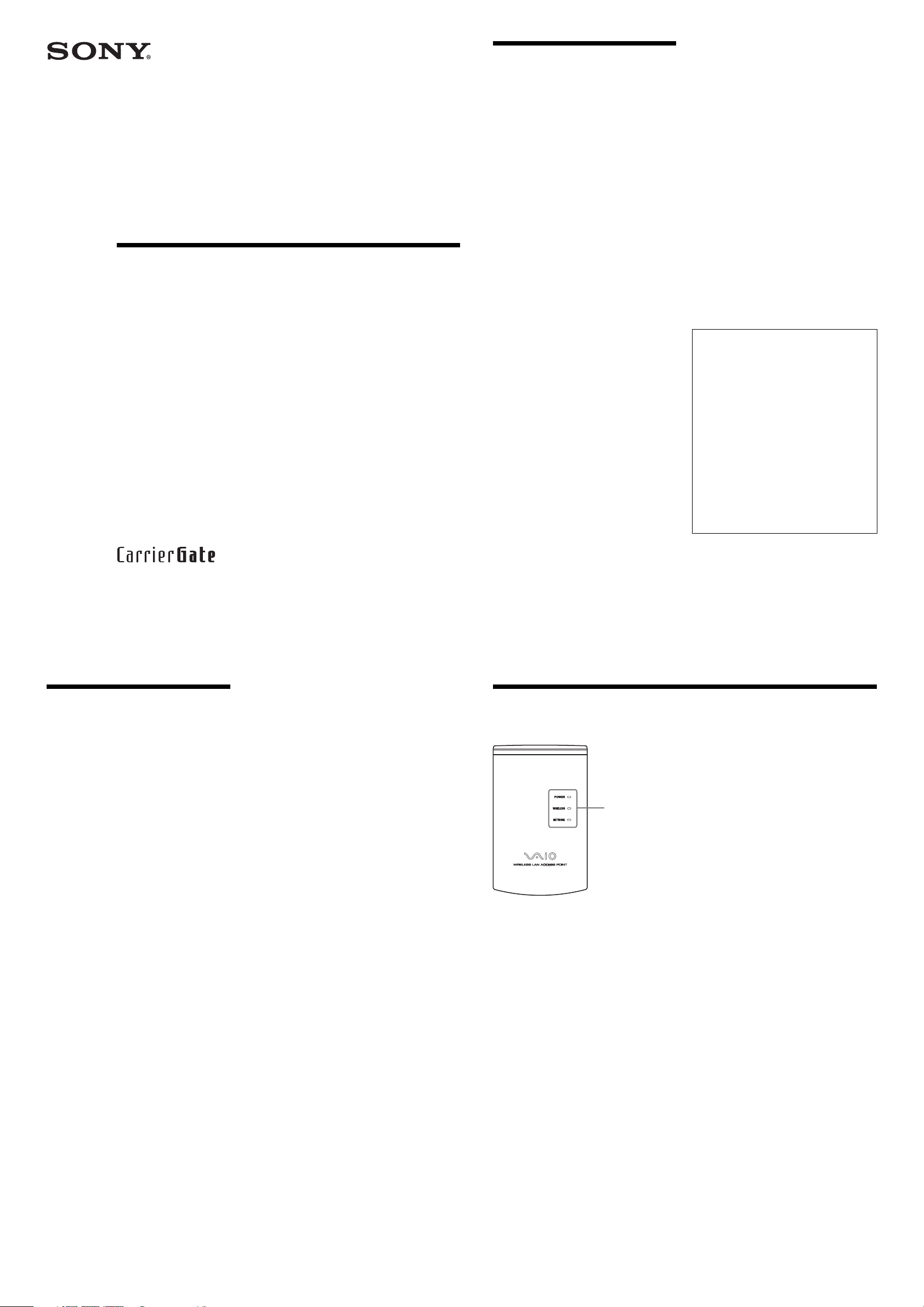
Names of parts and functions
Indicator
POWER
Lights when power is supplied.
WIRELESS
Flashes while data is exchanged through a
wireless LAN.
NETWORK
Lights when an Ethernet cable is connected to
the NETWORK connector.
Wall-mounting screw holes
Are used to mount the Access Point to a wall.
For details, see the Quick Start Guide supplied
with the Access Point.
MAC address label
The MAC address of your Access Point is
printed.
Reset switch
Is used to return the Access Point to its default
settings.
For details, see Online Help.
NETWORK connector
Is used to connect the Access Point to a DSL
modem, ISDN router, broadband router, or
Ethernet hub using an Ethernet cable.
DC IN 5V jack
Connects to the AC power adapter.
Page 2

Precautions
Specifications
Getting help
AC adapter
Use ony the supplied AC adapter. Other AC
adapters may cause a failure in the Access Point.
Safety
Do not drop the Access Point. Careful handling will
help prevent damage.
Installation
Do not place the Access Point where it will be
exposed to the following conditions:
• Unstable surfaces.
• High humidity or poor ventilation.
• Excessive dust.
• Direct sunlight or extreme heat.
• Closed cars.
• Magnetized locations (near magnets, speakers,
or televisions).
• Locations exposed to frequent vibration.
• Locations where the transmission of radio
waves may be obstructed by metal plates or
concrete walls
Operation
Exposure to cold-to-hot temperature extremes or
very damp environments may cause moisture to
condense on internal parts. This may prevent the
Access Point from operating properly.
If this should happen, unplug the AC adapter from
the power outlet and let the Access Point sit for two
to three hours or until the moisture evaporates.
Cleaning
Clean the casing with a soft cloth, lightly moistened
with water or a mild detergent solution. Do not use
any type of abrasive pad, scouring powder or
solvent such as alcohol or benzene. This may
damage the finish of the casing.
Power
AC100-240 V, 50/60 Hz
(The power cord plug is for use with AC 120 V.)
Power consumption
Approximately 4 W
Interface
100BASE-TX/10BASE-T (RJ-45)
Maximum external dimensions
Approximately 3.1 × 5 × 1.1 inches (w/h/d)
(Approximately 78 × 125 × 29 mm (w/h/d))
Mass
Approximately 7 oz (Approximately 200 g)
(Not including the AC adapter)
Maximum connection distance
Approximately 130 feet (40 m) in direct line of sight
with no obstacles
(The maximum connection distance depends on the
environment.)
Recommended number of units
connected
16 units or less (number of clients)
Protocol support
TCP/IP
Standard
IEEE 802.11b/IEEE 802.11 (wireless connection)
IEEE 802.3 (wired connection)
Radio frequency
2.4 GHz (channel 1 to 11, ISM band)
WEP (Data encryption)
64 bits/128 bits
Modulation method
DS-SS (IEEE 802.11b compliant)
Operating temperature
41°F to 95°F (5°C to 35°C)
(no condensation)
Storage temperature
-4°F to 140°F (-20°C to 60°C)
(no condensation)
Design and specifications are subject to change
without notice.
This section describes how to get help and support
from Sony, as well as troubleshooting tips for your
Wireless LAN Access Point.
About Sony’s Support Options
Sony provides several support options for your
Wireless LAN Access Point.
❒ Quick Start Guide explains how to install the
Wireless LAN Access Point.
❒ Access Point Online Help explains how to
configure the Access Point.
❒ The Sony Wireless LAN Access Point
support Web site
http://www.sony.com/wirelesslansupport/
provides the latest information on your Wireless
LAN Access Point.
❒ The Sony e-mail support service answers
your questions by electronic mail. Just send your
question in an e-mail message and a customer
service representative will reply. To send a
question to Sony e-mail support, fill out the email form at
http://www.sony.com/wirelesslansupport/
❒ The Sony fax-back service provides you
with answers to commonly asked questions. You
can use this automated service to request a list of
available topics then select the topics you want to
receive. To contact the Sony fax-back service,
call 1-877-760-7669.
❒ The Sony Customer Information Services
Center offers information about your Access
Point, Wireless LAN PC Card, and other Sony
products that work with your computer. To
contact the Sony Customer Information Services
Center, call 1-877-760-7669. Open 24
hours/day, 7 days/week.
Page 3
4-664-608-11(1)
Continued on next page
Installing the Access Point
Step 1
Preparation
Install the Access Point
Verify your computer's configuration and connection type.
Install the Access Point, connect it to a DSL modem, ISDN router, or broadband
router, or to an Ethernet LAN, and then turn the power on.
Step 2
Configuring the Access Point
Change the Access Point settings
Use the newly installed utility software to change the Access Point settings.
Step 5
Install the utility software
Use the CD-ROM provided to install the utility software that searches for the Access
Point.
Step 4
Change the computer settings
Change the computer's wireless communication settings in accordance with the new
Access Point settings that were changed in step 5.
Step 6
Establishing a Wireless Connection
Establish communication between the computer and
the Access Point
Configure wireless communication settings for your computer, and establish wireless
communication with the Access Point under the default settings. Although
communication is possible under the default settings, from a security standpoint it is
best to also perform the following steps and change the default settings.
Step 3
2.4GHz
Wireless LAN Access Point
(Bridge Type)
Quick Start Guide
Before reading this guide, be sure to read the supplement entitled
“Read This First.”
This guide provides an overview of the functions of the 2.4GHz Wireless LAN Access Point PCWA-A220, and explains the preparations that
are necessary before the Access Point can be put into operation.
Capabilities
Wireless access to the Internet from a variety of locations
The Wireless LAN Access Point PCWA-A220 (“Access Point” hereafter) is an IEEE 802.11bcompliant bridge-type 2.4 GHz wireless LAN access point. You can use the Access Point as a base
station to construct a wireless LAN environment with computers that contain a wireless LAN PC card.
If you want to enable the computers that are connected to the wireless LAN to access the Internet,
simply connect the Access Point to a DSL modem, cable modem, ISDN router, broadband router or
another similar communication device, or to an Ethernet LAN (wired LAN) that is connected to the
Internet.
Notes
• Use an Ethernet cable to connect the Access Point to the communication device. You cannot use a USB connection to
connect the Access Point to a communication device.
• Connect the Access Point to a communication device that is equipped with a router function. If you connect the Access
Point to a communication device that is not equipped with a router function (such as a cable modem), you will also need a
broadband router.
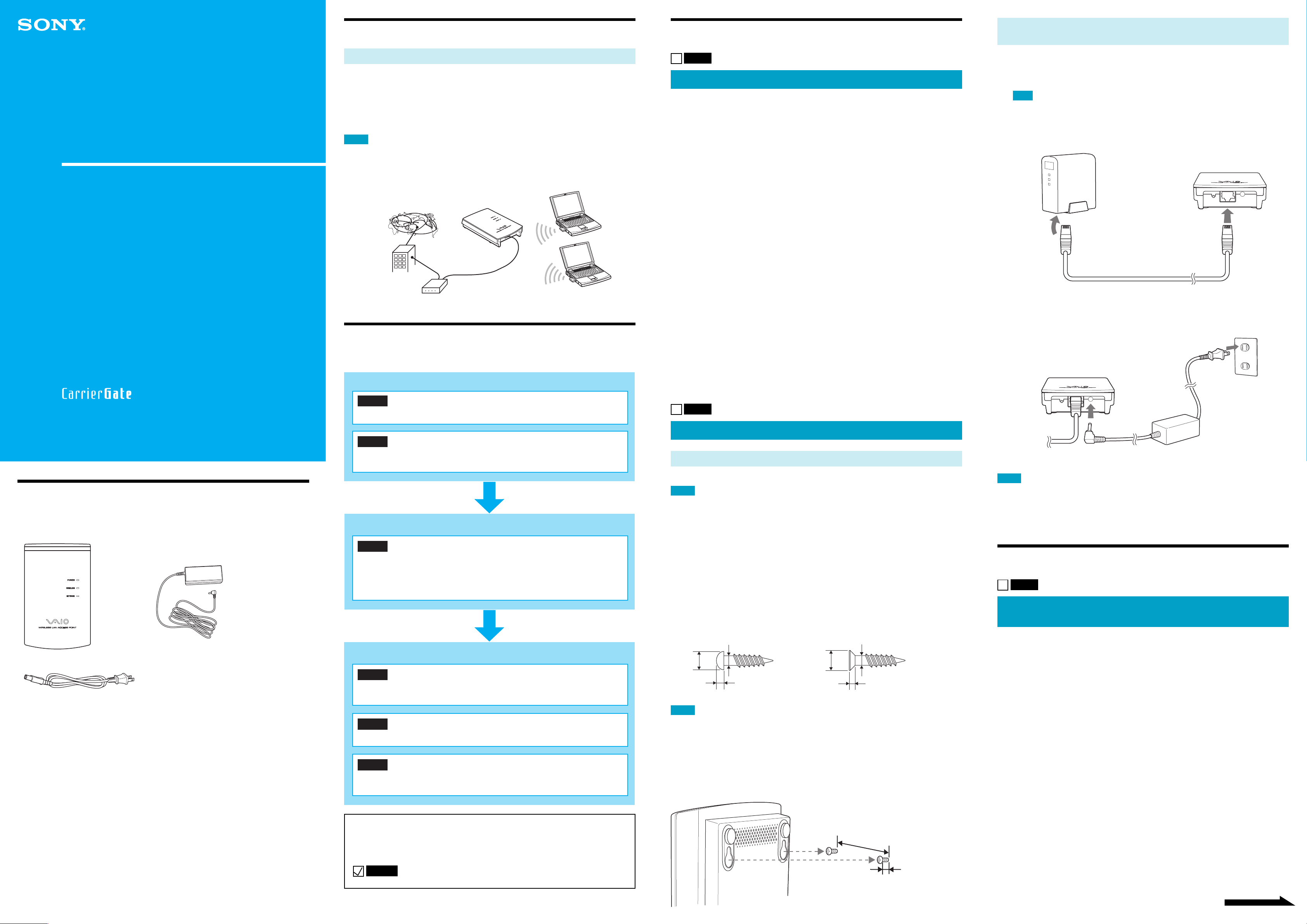
Steps to Installing, Connecting, and
Installing the Access Point
Step 1
Preparation
Complete the following preparations before setting up the Access Point.
Set up your wireless LAN PC card.
Install the wireless LAN PC card in the computer, and then install any device drivers and utility
software that are necessary in order to use the wireless LAN PC card.
For details, refer to the instruction manual provided with the wireless LAN PC card.
Confirm the method to be used for making the wireless connection
between your computer and the Access Point.
Confirm the method to be used for making the wireless connection between the computer in which the
PC card is installed and the Access Point.
For details, refer to the instruction manual provided with the wireless LAN PC card.
(Specific settings are explained in Step 3.)
Confirm the method to be used for connecting the Access Point to
the DSL modem, ISDN router, or broadband router, or to an Ethernet
LAN.
Make the connection using either a straight or a crossed Ethernet cable. When connecting to a
communication device, use the same type of cable as when connecting the communication device
directly to the computer.
z Hints
• For details on the type of cable to use when connecting the Access Point to a communication device, refer to the
instruction manual for the communication device.
• The Ethernet cable that is provided with the Access Point is a straight-through cable. If a cross-over cable is needed, you
must obtain it separately.
• Connect the Access Point to a communication device that is equipped with a router function. If you connect the Access
Point to a communication device that is not equipped with a router function (such as a cable modem), you will also need a
broadband router.
Connecting to a DSL modem, ISDN router, or broadband
router, or to an Ethernet LAN
1
Use an Ethernet cable to connect your DSL modem, ISDN router,
broadband router or an Ethernet LAN hub to the NETWORK connector
on the Access Point.
Note
Make the connection using either a straight-through or a cross-over Ethernet cable. Use the same type of
cable as when connecting a communication device directly to the computer. For details on what cable to
use, refer to the instruction manual for the communication device that you are using. If you are
connecting the Access Point to an Ethernet LAN hub, use a straight-through Ethernet cable.
(The Ethernet cable that is provided with the Access Point is a straight-through cable.)
Ethernet cable
2
Connect the Access Point to a power outlet.
z Hint
The Access Point does not have its own power switch.
PCWA-A220
Sony Corporation ©2002 Printed in Japan
Check the Packing List
Once you have unpacked the unit, make sure that all of the following items are present:
• Access Point • AC adapter
• Power cable
• Ethernet cable (straight-through)
• CD-ROM (Setup disc)
• “Read This First”
• Quick Start Guide (this manual)
• Warranty
• One set of printed materials
Setting Up
Adjust your computer’s firewall settings
If you are using the Windows XP Internet Connection Firewall or a personal firewall function provided
by virus scanning software, it may be necessary to adjust the security level setting. Refer to the note
found at the end of this manual on “Computer Firewall Functions.”
Step 2
Install the Access Point
Installation
Install the Access Point in a stable location where it will not tip over or fall.
Notes
• Do not install the Access Point on an unstable surface.
• Do not install it on a shelf or other place where jarring or vibration might cause it to fall.
• Do not install the Access Point in any location where passers-by might accidentally come in contact with the Access Point
or its cabling.
• When installing the Access Point, be sure to read the “Read This First” supplement as well.
If you hang the Access Point on a Wall...
You can use the mounting holes on the bottom of the access point to hang the Access
Point on screws or nails in a wall.
There are no mounting brackets provided with the Access Point. Use sturdy screws or nails that will be
able to bear the weight of the Access Point.
■ Recommended screws
• Roundhead screws • Flathead screws
(shaft diameter 3.1 mm) (shaft diameter 3.1 mm)
Ø5.7
Ø3.1
2.3
Notes
• Using two screws or other fasteners, ensure that the Access Point is securely set on the wall. When fastening the Access
Point to a wall with screws, retighten them after mounting the Access Point.
• Select a location that will hold the weight of the Access Point when mounting it on the wall. If the location cannot hold
the weight of the Access Point, the Access Point may drop and cause an accident.
• When mounting the Access Point on walls made of plasterboard or other fragile material, make sure that the material is
strong enough to support the unit’s weight and use special screw fasteners or other fixtures that are made for use with that
material. If the unit is fastened with ordinary screws, there is a danger that it may fall.
• When mounting the Access Point on the wall, be careful not to drop the Access Point or the tools used for doing the work.
Dropping the unit or tools could result in unforeseeable accidents.
(unit: mm)
Ø6.2
Ø3.1
1.8
Notes
• Depending on your communication service provider, it may be necessary to make certain settings in your computer and
the connection tool. If such settings are necessary, make them before proceeding to Step 3.
• Connect the Access Point to a communication device that is equipped with a router function. If you connect the Access
Point to a communication device that is not equipped with a router function (such as a cable modem), you will also need a
broadband router.
Establishing a Wireless Connection
Step 3
Establish communication between the computer
and the Access Point
Make wireless communication settings for your computer, and establish communication with Access
Point. For details on the wireless communication settings for your computer, refer to the instruction
manual provided with your wireless LAN PC card.
The default settings for Access Point are as follows: Make the wireless communication settings for your
computer in accordance with these default settings.
• Network Name (SSID): default
• Encryption (WEP): invalid
z Tips
• The manufacturer of your equipment may refer to the network name (SSID) setting as “ESSID,” “Network ID” or some
similar term.
• The manufacturer of your equipment may refer to the encryption setting as “security” or some similar term.
Although communication is possible under the default settings, from a security standpoint it is best to
also perform the following steps and change the default settings.
• Microsoft and Windows are registered trademarks of Microsoft Corporation in the U.S. and in other countries.
• In this manual, the term “Windows XP” is used to refer to both Microsoft Windows XP Home Edition and Microsoft
Windows XP Professional.
• Ethernet is a registered trademark of Fuji Xerox.
• Netscape and Netscape Communicator are trademarks or registered trademarks of Netscape Communications
Corporation.
• Other system names and product names that appear in this manual are registered trademarks or trademarks of their
respective owners. Note that the ™ and ® symbols are not used in this manual.
z Hint
In this guide, each step is preceded by a check box. After you complete each step, confirm that you have performed
all of the necessary tasks described in that step, and then check off the check box before proceeding to the next step.
Example:
Step 1
Approx. 2.1 inches
Approx. 0.1 inch
Page 4
Configuring the Access Point
Step 4
Install the utility software
Install the utility software that searches for the Access Point.
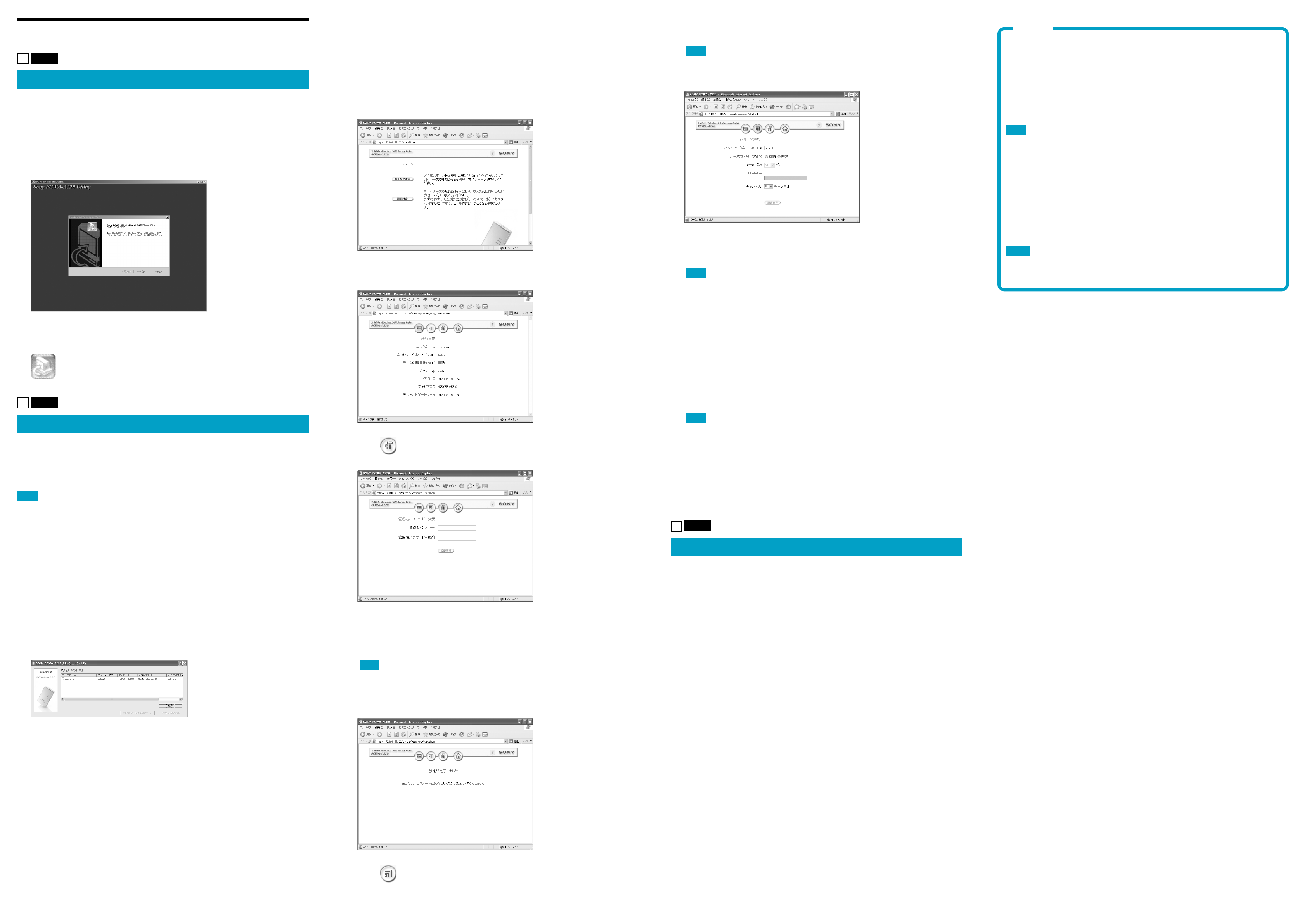
1
Set the CD-ROM that was provided with the Access Point into the
computer containing the wireless LAN PC card.
2
Double-click “Setup.exe” in the CD-ROM.
This launches the Installer program. Follow the onscreen instructions and install the utility
software.
4
If you click “IP Address Setup” in Step 3, select “Static (Manual).” Enter
the IP address, netmask, and default gateway, and then click “Execute
Setup.”
z Hint
Enter settings that are appropriate for the Ethernet LAN settings. If the network has an administrator,
ask the network administrator what settings to use.
5
Click “Access Point Setup Page.”
The following screen appears.
6
Click “Easy Setup.”
The Quick Setup screen appears.
11
In the “Password” field, enter the administrator password that you set in
Step 8, and then click “OK.”
Note
Do not enter anything in the “User Name” field.
The Settings screen appears.
12
Enter the Network Name (SSID).
The Network Name (SSID) is an ID that distinguishes the wireless network. Enter a character
string of up to 32 letters, numbers, and symbols.
Note
Make a note of the network name to make sure that you do not forget it.
Note
Computer Firewall Functions
When using Windows XP’s “Internet Connection Firewall”
Enabling the Windows XP Internet Connection Firewall may prevent your computer from being
recognized by your network. (This feature is disabled under Windows XP’s default settings.) If
you have enabled this feature and are unable to configure your Access Point or cannot recognize
the Access Point that you would like to configure, try disabling the Internet Connection Firewall
feature, and try again to communicate with your Access Point.
Note
Network security is an important issue. You are urged to consider carefully how best to protect your computer.
When using a personal firewall function provided by virus
scanning software or network security software
Virus scanning software and network security software sometimes includes a function called a
“personal firewall” that is designed to prevent illegal access by outside entities. Depending on the
software, the security level of this function may be initially set to a high level. If this high
security level setting is left in effect, it may be impossible for an outside entity to access your
computer. This can cause problems such as not being able to connect to the network when
changing the Access Point’s settings. In this event, lower the security level in order to permit the
network connection. For details, refer to the instruction manual and online help for your software.
Notes
• Pay special attention to security issues.
• Please note that we are not able to respond to questions on this topic.
z Hint
Depending on your computer’s settings, the file name “Setup.exe” may appear as “Setup.” If there are
multiple files named “Setup” in the same folder, double-click the one that has the following icon:
Step 5
Change the Access Point settings
Display the Access Point setup web page in order to make the Access Point settings.
Compatible browsers:
Internet Explorer 5.0 or later
Netscape Communicator 4.78 or later
Netscape 6.1 or later
Note
• When displaying the Access Point setup web page from the Scan Utility software, set one of the Web browsers above as
the default.
• Do not use a proxy for the Access Point IP address in the Web browser Proxy setting.
7
Click .
The Administrator Password Setup screen appears.
13
Select “Enabled” for “Encryption (WEP)” and set “Key Length” to “64.”
z Hints
• “Encryption (WEP)” is a function that encrypts wireless communication in order to prevent illegal access to the
network. The “WEP Key” is the password that is needed in order to use a network in which communications are
encoded by WEP.
• For the sake of this example, it is assumed that “64” (64 bits) is set for the “Key Length,” but “128” (128 bits) may
also be selected as well. If you are using the PCWA-C100, however, select “64.” (The PCWA-C100 does not
support 128-bit encryption keys.)
14
Enter the WEP key.
Enter a character string of 5 letters, numbers, and symbols. If “128” was selected for “Key
Length,” enter a character string of thirteen letters, numbers or symbols.
Note
Make a note of the encryption key to make sure that you do not forget it.
15
Click “Execute Setup.”
16
Close the Web browser.
z Hint
If you change the wireless settings, the connection with the Access Point will be lost. After finishing
Step 5, read Step 6 carefully and then establish the connection again.
Step 6
z Hint
The Access Point setup web page is saved in the Access Point internal memory.
1
Click the “Start” button, point to “Programs” (when using Windows XP,
select “All Programs”), and click “Wireless LAN,” “PCWA-A220,” and
“Scan Utility” in that order.
The Scan Utility starts up, and automatically searches for Access Points on the same network.
Once the Scan Utility finishes searching for Access Points, it displays a list of Access Points.
z Hint
If the Scan Utility does not find any Access Points, move the computer to a location that provides good
conditions for wireless communication with the Access Point, and then click the “Scan” button to search
again.
2
Select the Access Point to which you want to connect from the list of
Access Points that were found by the Scan Utility.
z Hint
If multiple Access Points are shown in the list, check the MAC addresses. Each Access Point’s MAC
address is printed on a bar code label located near the NETWORK connector on the back of the Access
Point. After checking the MAC address, be sure to reconnect the Ethernet cable.
8
In the “Administrator Password” field, enter a character string consisting
of up to 16 letters, numbers or symbols, and then enter the same string
again in the “Administrator Password (Confirmation)” field.
Note
Make a note of the administrator password to make sure that you do not forget it.
9
Click “Setup.”
The new settings are applied to the Access Point, and the Setup Completed screen appears.
Change the computer settings
Change the computer’s wireless communication settings in accordance with the new Access Point
settings that were changed in step 5. For details on how to make these settings, refer to the instruction
manual provided with your wireless LAN PC card.
Once you have changed the computer’s settings, you will be able to connect with the Access Point
again.
For details on the Access Point settings, refer to the online help.
Displaying Online Help
Click the “Start” button, select “Programs” (when using Windows XP, select “All Programs”), and then
click “Wireless LAN,” “PCWA-A220,” and “Online Help” in that order.
3
If the Access Point is connected to an Ethernet LAN that does not
operate on a DHCP server, click “IP Address Setup.”
If the Access Point is not connected to an Ethernet LAN, or if a DHCP server is running, this
operation and Step 4 are unnecessary. Proceed to Step 5.
10
Click to display the Wireless Settings screen.
The Network Password Input screen appears.
 Loading...