

Page 1
www.fairchildsemi.com
TMC22091/TMC22191
Digital Video Encoders/Layering Engine
Features
• All-digital video encoding
• Internal digital oscillators, no crystals required
• Multiple input formats supported
– 24-bit and 15-bit GBR/RGB
–YCBCR422 or 444
– Color indexed
• 30 overlay colors (TMC22191)
• Fully programmable timing
• Supports input pixel rates of 10 to 15 Mpps
• 256 x 8 x 3 color look-up tables (bypassable on
TMC22191)
• 8-bit mask register
• 8-bit composite digital video input
• Hardware and 24-bit data keying
• Synchronizes with TMC22071 Genlocking Video
Digitizer
• 8:8:8 video reconstruction
• SMPTE 170M NTSC or CCIR Report 624 PAL
compatible
• Supports PAL-M and NTSC without pedestal
• Simultaneous S-VIDEO (Y/C) NTSC/PAL output
• 10-bit D/A conversion (three channels)
Logic Symbol
• Controlled edge rates
• 3 power-down modes
• Built-in color bars and modulated ramp test signals
• JTAG (IEEE Std 1149.1-1990) test interface
• Single +5V power supply
• 84 lead PLCC package
• 100 lead MQFP package
Description
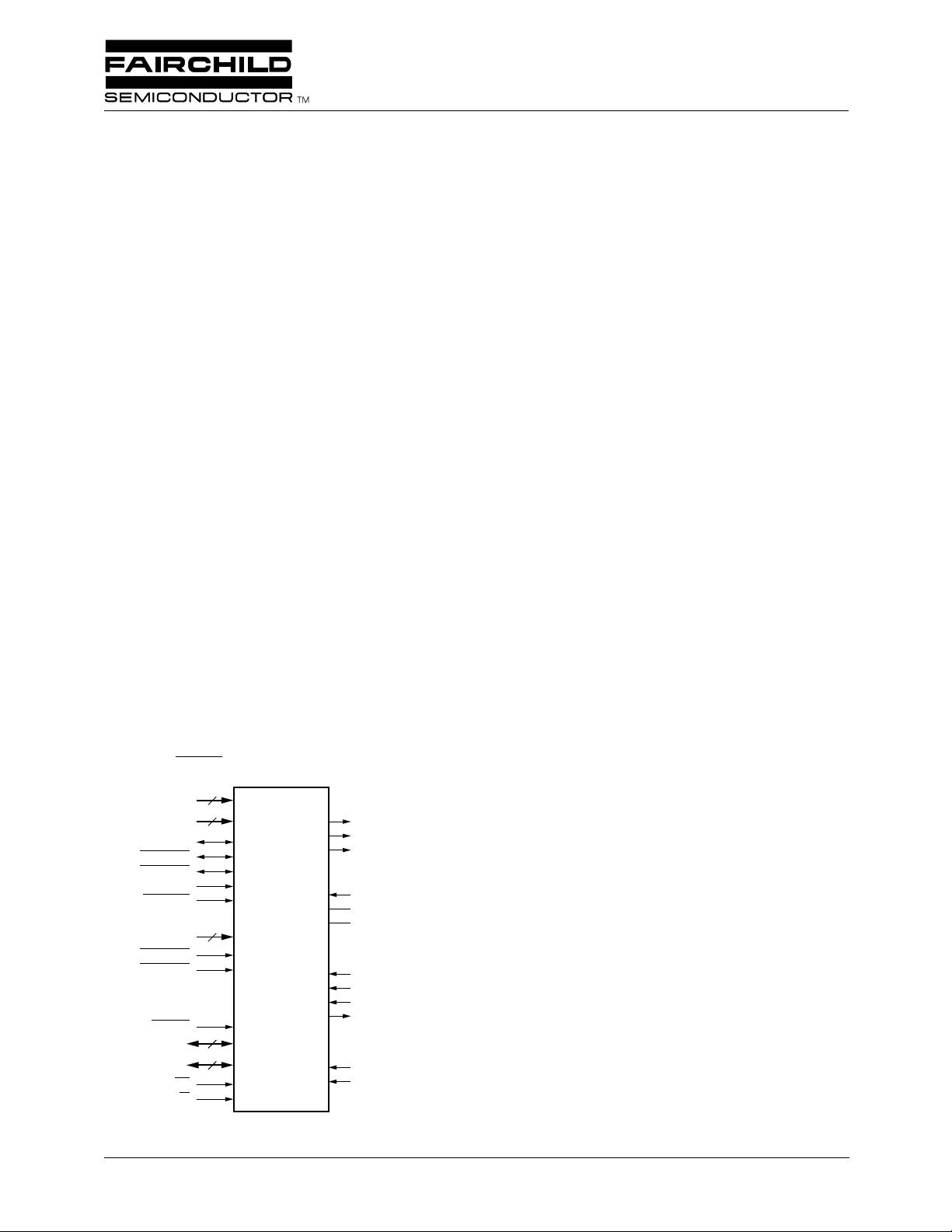
The TMC22x91 digital video encoders convert digital computer image or graphics data (in RGB, YCBCR, or color
indexed format) or a CCIR-601 signal into a standard analog
baseband television (NTSC or PAL) signal with a modulated
color subcarrier.
Both composite (single lead) and S-VIDEO (separate
chroma and luma) formats are active simultaneously at the
three analog output pins, each of which generates a standard
video-level signal into doubly-terminated 75Ω load.
The TMC22x91 accepts digitized video from the companion
TMC22071 Genlocking Video Digitizer. Soft switching
between video sources is done under either hardware or
programmable data control.
The TMC22191 offers 4-layer keying capability, bypassable
CLUT, and 30 Overlay colors.
BYPASS and OL
OL
D
A
23-0
4-0
PDC
KEY
7-0
7-0
1-0
CS
R/W
24
6
8
8
2
PD
VHSYNC
VVSYNC
INTERFACE
FRAME BUFFER
BYPASS
CVBS
GHSYNC
GVSYNC
GENLOCK
INTERFACE
RESET
INTERFACE
MICROPROCESSOR
on TMC22191 only.
4:0
TMC22x91
DIGITAL
VIDEO
ENCODER
27008A
CHROMA
LUNA
COMPOSITE
V
REF
COMP
R
REF
TDI
TMS
TCK
TDO
LDV
PXCK
The TMC22x91 is fabricated in a submicron CMOS process
and packaged in an 84 Lead Plastic Leadless Chip Carrier, or
in a 100 Lead Metric Quad Flat Pack. Performance is guaranteed from 0°C to 70°C.
OUTPUT
VIDEO
INTERFACE
ANALOG
INTERFACE
JTAG TEST
CLOCKS
Rev. 1.1.0
Page 2
TMC22091/TMC22191 PRODUCT SPECIFICATION
Block Diagram
OL
4-0
BYPASS
23-0
KEY
PDC
FORMATTER
MASK, KEY
COMPARATOR
Data Key
PD
VVSYNC
FRAME BUFFER INTERFACE
VHSYNC
G/R/Y MAP
B/G/C
B
R/B/C
R
256 x 8 x 3
COLOR
LOOK-UP
TABLE
BYPASS and OL
R/R-Y
INTER-
B/B-Y
POLATOR
4:2:2/4:4:4
G/Y
on TMC22191 only.
4:0
MATRIX
R-Y
B-Y
LPF
LPF
SYNC,
BLANK
INSERT
CHROMA
MODULATOR
INT
INT
10-bit
D/A
10-bit
D/A
CHROMA
LUMA
GHSYNC
GVSYNC
GENLOCK
INTERFACE
CVBS
7-0
CLOCK CONTROL JTAG
LDV
PXCK
CLOCKS MICROPROCESSOR
Functional Description
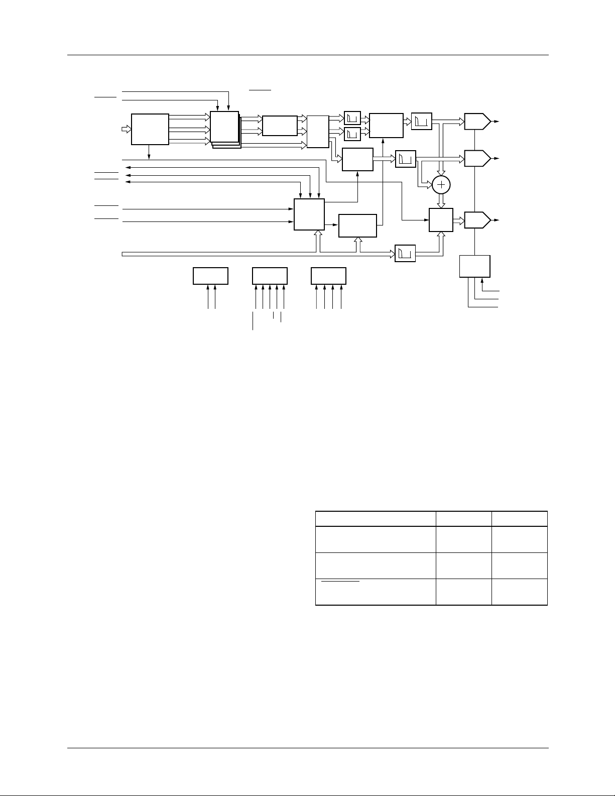
The TMC22091 and TMC22191 are totally integrated, fullyprogrammable digital video encoders with simultaneous
composite and Y/C (S-VIDEO) outputs. The TMC22x91
video outputs are compatible with SMPTE 170M NTSC,
CCIR Report 624 PAL, PAL-M, and NTSC without pedestal
television standards. No external component selection or
tuning is required.
The encoders accept digital image data at the PD port in one
of several formats, which are matrixed into luminance and
chrominance components. The chrominance signals are
modulated onto a digitally synthesized subcarrier. The luminance and chrominance signals are separately interpolated to
twice the pixel rate, and conv erted to analog levels by 10-bit
D/A converters. They are also digitally combined and the
resulting composite signal is output by a third 10-bit D/A
converter. This composite signal may be keyed (pixel rate
switching) with a second composite digital video signal presented to the encoder.
The output video frames may be internally timed by the
TMC22x91, synchronized with the external frame buffer, or
slaved to the companion Genlocking Video Digitizer
(TMC22071). All operational parameters are fully programmable over a standard microprocessor port.
Table 1 shows the key features that distinguish between the
TMC22091 and TMC22191. All of the information presented in this data sheet applies to both products unless otherwise noted. Statements, paragraphs, tables, and figures that
apply to only one or two of the encoders have notation specifying the applicable part number.
7:0A1:0
D
RESET
INTERFACE
DIGITAL
SYNC.
GEN.
CS
R/W
INTERFACE
TDI
TCK
TMS
JTAG TEST
SUBCARRIER
SYNTHESIZER
TDO
INT
INTERPOLATION
FILTERS
VIDEO
SWITCH
10-bit
D/A
D/A
REF.
COMPOSITE
V
REF
COMP
R
REF
ENCODED VIDEO OUTPUT
ANALOG
INTERFACE
27006A
Timing
The encoder operates from a single clock at twice the system
pixel rate. This frequency may be set between 20 MHz and
36 MHz (pixel rates of 10 Mpps to 18 Mpps). Within this
range are included CCIR-601, D2, and square-pixel formats,
as well as a variety of computer-specific pixel rates. An array
of programmable timing registers allows the software selection of all pertinent signal parameters to produce NTSC
(with or without 7.5 IRE pedestal) and PAL, and PAL-M
outputs.
Table 1. Comparing the TMC22x91 Encoders
Feature TMC22091 TMC22191
OL
pixel inputs for 30
4-0
No Yes
overlay colors
Number of video layers
2 4
supported
BYPASS input for
No Yes
bypassing CLUTs
Input Formatting
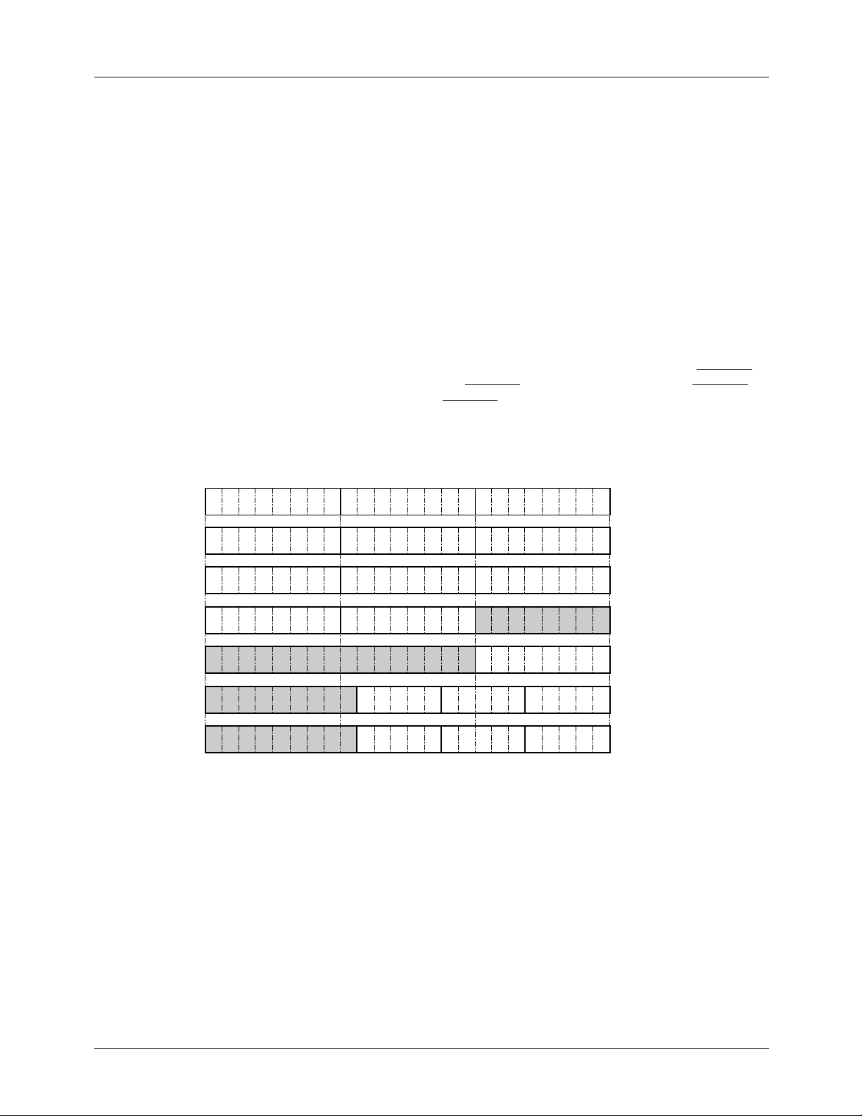
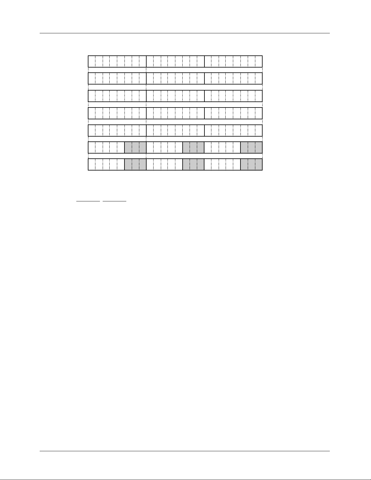
The input section accepts a variety of video and graphics formats, including 24-bit GBR and RGB, 15-bit GBR and
RGB, YCBCR422, YCBCR444, and 8-bit color-indexed data
(Figure 1a and 1b).
The input section of the TMC22x91 includes a key comparator which monitors the pixel data port with three independent
8-bit comparators, and invokes a video k ey when the selected
registers match the incoming data.
2
Page 3
PRODUCT SPECIFICATION TMC22091/TMC22191
Mask Register
A Mask Register is provided which is logically ANDed with
incoming color-index data to facilitate pixel animation and
other special graphics effects. The Mask Register is ahead of
the Data Key comparators and is enabled only when colorindex input is selected. Mask Register programming and
operation are similar to that of the 171/176 family of graphics RAMDACS.
Color Lookup Table
The Color Lookup Table (CLUT) is a 256 x 8 x 3 randomaccess memory. It provides means for offset, gain, gamma,
and color correction in RGB and YCBCR operating modes. It
provides a full 24-bit color lookup function for color-index
mode. It can be loaded in the same manner as a standard
VGA RAMDAC.
MODE
GBR444
MSB
23
G
7
16
15
G B R
G0B
7
Colorspace Conversion Matrix and
Interpolator
The matrix converts RGB data (whether from RGB inputs or
color-indexed CLUT data) into Y, B-Y, R-Y format for
encoding. In input configurations where the pixel input is
already in Y, B-Y, R-Y format, the matrix is bypassed. When
pixel data is input in YCBCR422 format, the interpolation filters produce YCBCR444 for encoding.
Sync Generator
The TMC22x91 can operate in Master, Genlock, or Slave
modes. In Master and Genlock modes, the encoder internally
generates all timing and sync signals, and provides Horizontal Sync, Vertical Sync, and Pixel Data Control (PDC) to the
external frame buffer circuitry. PDC is independently selectable to function as an input or an output. In Genlock mode,
the TMC22x91 timing is controlled by the TMC22071 Genlocking Video Digitizer over the CVBS
and GHSYNC. The encoder, in turn, produces VHSYNC,
VVSYNC, and PDC for the frame buffer interface.
Format Control Register
8 7
B0R
7
LSB
R
0
0
bus, GVSYNC,
7-0
MSB LSB
00011000
RGB444
YCBCR444
YCBCR422
COLOR INDEX
GBR15
RGB15
R
7
Y
7
Y
7
R G B
Y C
Y C
R0G
Y0C
Y
0
R
G0B
7
CB0R
R7
C
B0
C
R0
P
7
G
B
0
4
R
G
0
4
C
Pixel
B
R
0
4
G
B
0
4
7
B7
C
B7
C
R7
G
4
R
4
B
/
C
B
G B R
R G B
R
B
R
P
R
B
24300A
R0
00010000
0
00011100
00011101
0001X011
0
00011010
0
00010010
0
Figure 1a. Pixel Data Format
3
Page 4
TMC22091/TMC22191 PRODUCT SPECIFICATION
MODE
GBR444
RGB444
YCBCR444
YCBCR422
COLOR INDEX
RGB15
GBR15
MSB
23
G
7
R
7
Y
7
Y
7
P
7
R
4
G
4
and CR are loaded on alternate LDV cycles
*C
B
G B R
R G B
Y C
Y C
Pixel
R G B
R
0
G B R
G
0
Figure 1b. Pixel Data Format (TMC22191 when CLUTs are Bypassed)
16
G0B
R0G
Y0C
Y
0
P
0
15
7
7
B7
C
B7
P
7
G
4
B
4
In Slave mode, VHSYNC, VVSYNC, and PDC (optional)
are inputs to the TMC22x91. These inputs determine when
new lines, frames, and active picture areas begin. The external controlling circuitry needs to establish the correct timing
for these signals.
Horizontal and vertical synchronization signals are digitally
generated by the TMC22x91 with controlled rise and fall
times on all sync edges, the beginning and end of active
video, and the burst envelope. All elements of horizontal
sync timing are programmable, as are the frequency, phase,
and duration of color burst.
Video Input
The TMC22x91 accepts genlocked synchronization data and
digital composite video signals from the TMC22071 Genlocking Video Digitizer over the 8-bit CVBS bus. The
encoder synchronizes its digital subcarrier oscillator to the
video input from the TMC22071 with this data. The composite video data output from the TMC22071 is passed to the
internal video switch for keying with the encoded pixel data.
Chroma Modulator
A 32-bit digital subcarrier synthesizer feeds a quadrature
modulator, producing a digital chrominance signal. The relative phases of the burst and active video portions of the subcarrier can be individually adjusted to compensate for
external phase errors and to effect a hue control.
Interpolation Filters
Interpolation filters on the luminance and chrominance signals double the pixel rate in preparation for D/A conversion.
This band-limited process greatly simplifies the output filtering required following the D/A converters and dramatically
reduces sin(x)/x distortion.
B
B
Pixel
G
0
B
0
Format Control Register
8 7
B0R
7
G0B
7
CB0C
R7
*
CB0C
R7
P
P
7
0
B
4
R
4
C
R
C
R
Pixel
B
R
LSB
0
MSB LSB
R
B
C
R0
*
C
R0
P
0
0
24393A
01011000
0
01010000
0
0101X000
0101X001
0101X011
0
01010010
01011010
An interpolation filter on the CVBS data similarly raises the
sample rate of the video signal, for mixing with the encoded
pixel data.
Composite Video Switch
The Composite Video Switch selects between the composite
video input (CVBS) and the composite encoded pixel data
on a pixel-by-pixel basis, under the control of a key function.
Keying may be managed by hardware or software. The hardware key input (KEY pin) directly controls the video switch.
The encoder may be programmed to operate with a data key,
represented by three 8-bit registers that compare with the 24
input bits. They operate in all input modes and may be individually enabled or disabled.
D/A Converters
The analog outputs of the TMC22x91 are the outputs of
three 10-bit D/A converters, operating at twice the pixel
clock rate. The outputs are capable of driving standard video
levels into a doubly-terminated 75Ω coaxial video cable
(37.5Ω total load). An internal voltage reference is provided
which can be used to provide reference current for the three
D/A converters. For accurate video levels, an external fixed
or variable voltage reference source is recommended. The
video signal levels from the TMC22x91 may be adjusted to
overcome the insertion loss of analog low-pass output filters.
The D/A converters on the TMC22x91 may be powereddown via Control Register 0E bits 5 and 6. The
COMPOSITE D/A is controlled by bit 6 and the LUMA and
CHROMA D/A converters are controlled by bit 5.
4
Page 5

PRODUCT SPECIFICATION TMC22091/TMC22191
Microprocessor Interface
The microprocessor interface employs a 13 line format. The
RESET pin sets all internal state machines to their initialized
conditions, disables the analog outputs, sets the internal
SRESET bit LOW (reset condition), and places the encoder
in a power-down mode. All register and CLUT data are
maintained in power-down mode. If the HRESET bit is set
HIGH, line 1 field 1 is started when RESET goes HIGH, and
SRESET is ignored. If HRESET is LOW, the encoder
remains idle after RESET goes HIGH until Control Register
bit SRESET
Two address lines are provided and decoded for access to the
internal Control Registers and CLUT. Control Registers and
CLUT are accessed by loading a desired address through the
8-bit D
that address. Both the CLUT and the Control Registers are
self-indexing, allowing continuous reads or writes to successive addresses.
is set HIGH, which initiates line 1 field 1.
port, followed by the desired data read or write for
7-0
JTAG Test Interface
The TMC22x91 includes a standard 4-line JTAG (IEEE Std
1149.1-1990) test interface port, providing access to all digital input/output data pins. This is provided to facilitate component and board-level testing.
Test/Validation Mode
The TMC22x91 may be configured to produce standard
color bars or a 40 IRE modulated (or unmodulated) video
ramp, independent of any pixel or video data input. Color
bars are useful as an idle system output signal. The test signals may be used to verify proper operation of the analog
video signal chain.
TMC22090/TMC22190 Compatibility
The TMC22090 and TMC22190 are earlier versions of the
TMC22091 and TMC22191, respectively. They lack the following features of the newer versions:
1. Selectable Setup (to support NTSC EIA-J video output
for Japan)
2. PAL-M format (for South American applications)
3. Extended EH and SL intervals (to support pixel rates
above 15 Mpps)
4. Individual D/A power-down (to reduce total dissipation
when some outputs are not required)
5. Luminance I/O processing (to reduce flicker in graphics
applications)
These features are controlled by registers 0E and 0F, and
enabled by setting Register OE bit 7 to ONE. If an application of the TMC22x90 is programmed with this bit set to
ZERO (as recommended in the product documentation) then
the corresponding TMC22x91 will perform identically.
Though the earlier parts continue to be available, it is recommended that the newer devices be used in new designs for
the additional flexibility. Older designs may be readily
converted to the newer versions to take advantage of the
added features and lower cost of the later technology.
5
Page 6
TMC22091/TMC22191 PRODUCT SPECIFICATION
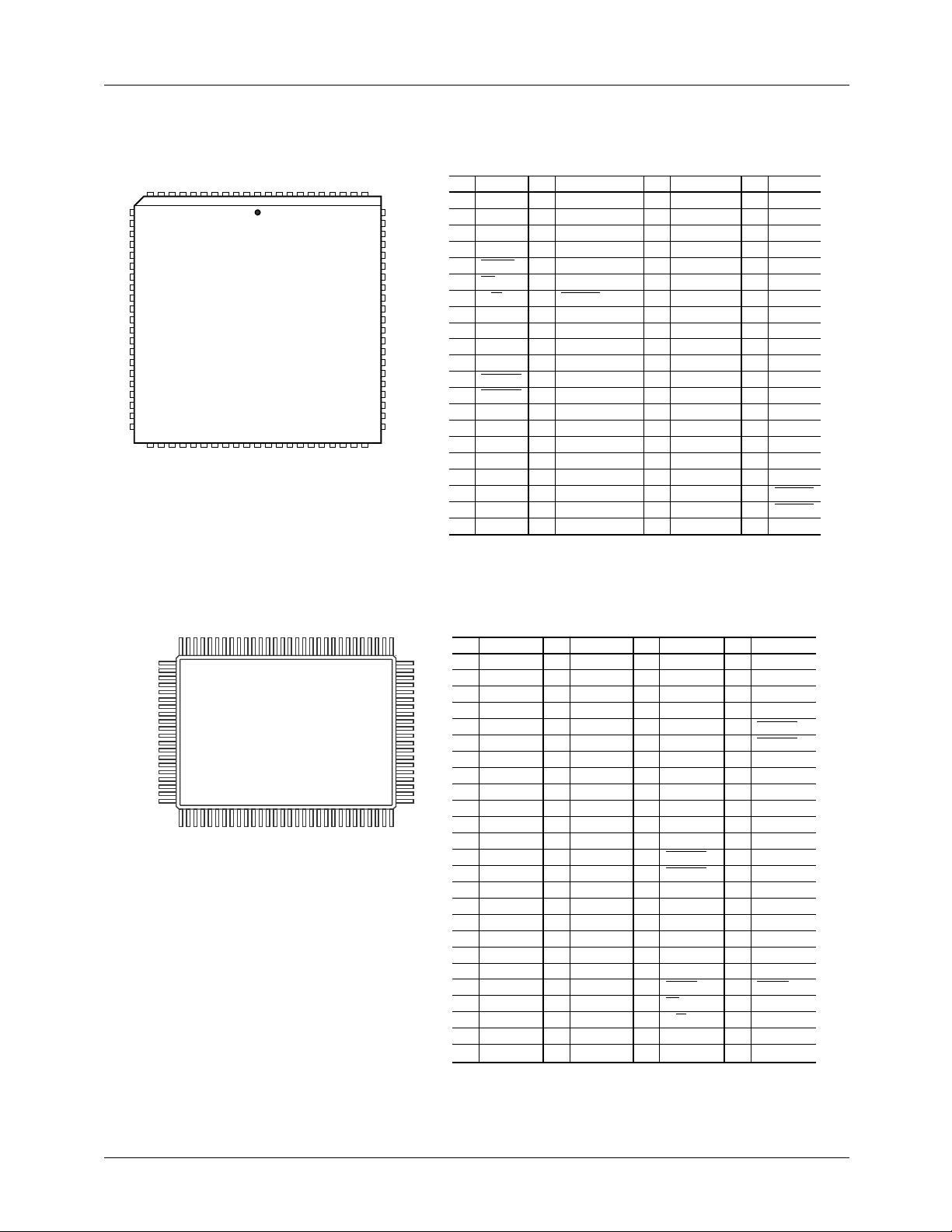
Pin Assignments
84 Lead PLCC
1
84
65-3751-01
Pin Name Pin Name
TDO
1
0
GND
7
6
5
4
3
2
1
0
22
2
1
0
TCK
23
TMS
24
TDI
25
D
26
GND
V
27
DD
BYPASS (TEST)
28
OL4 (TEST)
29
V
30
REF
R
31
REF
A
32
GND
COMPOSITE
33
A
34
GND
LUMA
35
A
36
GND
CHROMA
37
A
38
GND
COMP
39
V
40
DDA
V
41
DDA
V
42
DDA
1
2
3
4
5
6
7
8
9
10
11
12
13
14
15
16
17
18
19
20
21
CVBS
CVBS
CVBS
KEY
RESET
CS
R/W
A
A
D
PDC
VHSYNC
VVSYNC
D
D
D
D
D
D
D
D
Pin Name Pin Name
V
43
44
45
46
47
48
49
50
51
52
53
54
55
56
57
58
59
60
61
62
63
V
DDA
CVBS
CVBS
CVBS
CVBS
OL3 (TEST)
OL2 (TEST)
OL1 (TEST)
OL0 (TEST)
PD
23
PD
22
PD
21
PD
20
PD
19
PD
18
PD
17
PD
16
PD
15
PD
14
PD
13
PD
12
64
DD
D
65
66
67
68
69
70
71
72
73
74
75
76
77
78
79
80
81
82
83
84
GND
PD
11
PD
10
PD
9
PD
8
PD
7
PD
6
PD
5
PD
4
PD
3
PD
2
PD
1
PD
0
LDV
PXCK
D
GND
V
DD
GVSYNC
GHSYNC
CVBS
7
6
5
4
3
100 Lead MQFP
100
Note: Pin names in parentheses apply to TMC22091.
Pin Name Pin Name
PD
NC
1
COMPOSITE
2
NC
3
A
4
GND
LUMA
5
A
6
GND
NC
7
CHROMA
8
A
9
GND
COMP
10
NC
1
65-3751-02
11
12
13
14
15
16
17
18
19
20
21
22
23
24
25
NC
V
DDA
V
DDA
V
DDA
V
DDA
V
DDA
CVBS
CVBS
CVBS
CVBS
OL3 (TEST)
OL2 (TEST)
OL1 (TEST)
OL0 (TEST)
26
23
27
PD
22
28
NC
29
NC
30
NC
31
PD
21
32
PD
20
33
PD
19
34
PD
18
35
PD
17
36
PD
16
37
PD
15
38
PD
14
39
PD
13
40
PD
12
41
V
DD
42
D
GND
43
PD
7
6
5
4
11
44
PD
10
45
PD
9
46
PD
8
47
PD
7
48
PD
6
49
PD
5
50
PD
4
Pin Name Pin Name
D
51
52
53
54
55
56
57
58
59
60
61
62
63
64
65
66
67
68
69
70
71
72
73
74
75
PD
3
NC
NC
NC
NC
PD
2
PD
1
PD
0
LDV
PXCK
D
GND
V
DD
GVSYNC
GHSYNC
CVBS
CVBS
CVBS
CVBS
NC
KEY
RESET
CS
R/W
A
1
A
0
76
GND
77
PDC
78
NC
79
NC
80
VHSYNC
81
VVSYNC
82
D
7
83
D
6
84
D
5
85
D
4
86
D
3
87
D
2
88
D
1
89
D
0
90
3
2
1
0
TDO
91
TCK
92
TMS
93
TDI
94
D
GND
95
V
DD
96
BYPASS (TEST)
97
OL4 (TEST)
98
V
REF
99
R
REF
100
A
GND
Note: Pin names in parentheses apply to TMC22091.
6
Page 7
PRODUCT SPECIFICATION TMC22091/TMC22191
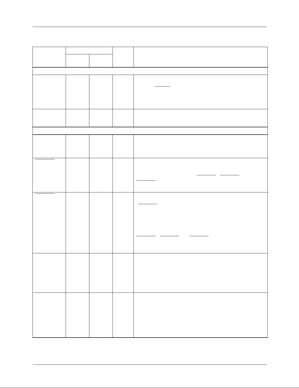
Pin Descriptions
Pin Number
84-Lead
Pin Name
Clocks
PXCK 79 60 TTL Master Clock Input. This 20 to 30 MHz clock is internally
LDV 78 59 TTL Pixel Data Load Clock. On each rising edge of LDV, data on
Frame Buffer Interface
PD
23-0
VHSYNC 12 80 TTL Horizontal Sync I/O. In Master and Genlock modes, the
VVSYNC 13 81 TTL Vertical Sync I/O. In separate V and H sync Master and
PDC 11 77 TTL Pixel Data Control. In Master mode, the TMC22x91 forces
KEY 4 70 TTL Hardware Key Input. When the HKEN control bit is set HIGH
PLCC
52-63,
66-77
100-Lead
MQFP
26, 27,
31-40,
43-51,
56-58
Value Pin Function Description
divided by 2 to generate the internal pixel clock, PCK, which a
LOW on RESET forces LOW. PXCK drives the entire
TMC22x91, except the asynchronous microprocessor interface
and the semi-synchronous LDV data input clock. All internal
registers are strobed on the rising edge of PXCK.
are latched into the input preload register, for transfer
PD
23-0
into the input demultiplexer on the next rising edge of PCK.
TTL Pixel Data Inputs. In YCBCR, GBR, RGB, and color-indexed
mode, pixel data enter the TMC22x91 on PD
format is found in Figures 1a and 1b. LDV is the clock that
controls the loading of pixel data.
TMC22x91 outputs horizontal sync on this pin. In Slave modes,
the TMC22x91 accepts and locks to horizontal sync input on
this pin (with vertical sync on VVSYNC). VHSYNC and
VVSYNC must be coincident since they are clocked into the
TMC22x91 on the same rising edge of PXCK.
Genlock modes, the TMC22x91 outputs vertical block sync
(VVSYNC LOW for the 2.5 (PAL) or 3 (NTSC) lines on which
vertical sync pulses occur). In composite sync (H and V sync
on same signal) Master and Genlock modes, the TMC22x91
outputs horizontal sync, vertical sync, and equalization over
this pin. In Slave mode, the TMC22x91 accepts and locks to
vertical sync input on this pin (with horizontal sync on
VHSYNC). VHSYNC and VVSYNC must be coincident such
that they are clocked into the TMC22x91 on the same rising
edge of PXCK.
PDC HIGH when and only when it wants active video from the
frame buffer. During blanking (syncs, equalization, burst, and
porches), it forces PDC LOW, signaling that it will ignore any
data presented over PD
forcing it HIGH allows the TMC22x91 to receive PD during the
active video state.
and hardware key pin, KEY, is HIGH, video data entering on
CVBS
signal is pipelined so the pixel that is presented to the PD port
when the KEY signal is invoked is at the midpoint of the soft
key transition. When HKEN is LOW, KEY is ignored. Like PD
data, KEY is clocked into the TMC22x91 on the rising edge of
LDV.
are routed to the COMPOSITE output. This control
7-0
. When PDC is used as an input,
23-0
. The specific
23-0
7
Page 8
TMC22091/TMC22191 PRODUCT SPECIFICATION
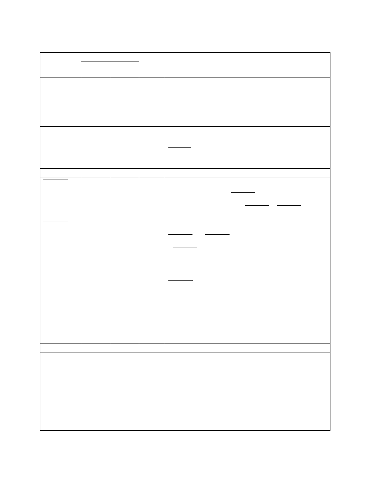
Pin Descriptions (continued)
Pin Number
84-Lead
Pin Name
OL
4-0
BYPASS
Genlock Interface
GHSYNC 83 64 CMOS Genlock Horizontal Sync. In Genlock mode, the TMC22x91
GVSYNC 82 63 CMOS Genlock Vertical Sync. In Genlock mode, the TMC22x91 will
PLCC
29, 48-51 97, 22-25 TTL Overlay Data Inputs (TMC22191 only). 30 of the 256
28 96 TTL CLUT Bypass Control (TMC22191 only). When BYPASS is
CVBS
7-0
Microprocessor Interface
D
7-0
A
1-0
44-47, 84,
1-3
14-21 82-89 TTL Data I/O Port. All control parameters are loaded into and read
8-9 74-75 TTL µProc Port Controls. As in a RAMDAC, this control governs
100-Lead
MQFP
18-21,
65-68
Value Pin Function Description
locations of the CLUT may be reserved for overlay operation.
These CLUT locations are directly accessed by five input pins,
OL
. OL
4-0
pixel basis and select which of the 30 overlay colors is to be
encoded. When all five OL
occurs.
HIGH, the CLUT is in the pixel data path within the TMC22191.
When BYPASS is LOW, pixel data bypasses the CLUT.
BYPASS is active only for certain modes of the Layering
Control Register (LCR) when the Format Control Register bit 6
is HIGH.
will start a new horizontal line (blank-to-sync-edge transition)
with each falling edge of GHSYNC. In non-genlock modes, the
TMC22x91 ignores GHSYNC. The internal pixel clock, PCK, is
aligned with the falling edge of VHSYNC or GHSYNC (Genlock
mode).
start a new vertical sync sequence at line 1 field 1 whenever
GVSYNC and GHSYNC are coincident such that they are
clocked into the TMC22x91 on the same rising edge of PXCK.
If GVSYNC falls at any other time, the TMC22x91 will assume
that this marks the start of field 2, and will ignore it (in odd-field
sync mode) or (in all-field sync mode) respond by generating a
single vertical sync pulse, followed by 2 (PAL) or 2.5 (NTSC)
lines of vertical sync, keyed to the next falling edge on
GHSYNC. See Interface Control Register bit 0 for odd-field and
all-field operation.
TTL Composite Video Inputs. The encoder receives digitized
video, subcarrier phase, and subcarrier frequency over this 8bit bus at the PCK rate. This data may be provided by the
companion TMC22071 Genlocking Video Digitizer. In Genlock
mode, the TMC22x91 expects subcarrier phase and frequency
data during each line’s horizontal sync interval, as well as video
data when keying is engaged, transferred at the PCK rate.
back over this 8-bit port. For digital testing, the five lower bits
can also serve as a two-cycle 10-bit data output port. For D/A
converter testing, it can be used as a 10-bit two-cycle input
port, facilitating, for example, ramp-based D/A converter
linearity tests.
whether the microprocessor interface selects a table address
or reads/writes table contents. It also governs setting and
verification of the TMC22x91’s internal operating modes, also
over port D
are entered into the TMC22191 on a pixel-by-
4-0
inputs are LOW, no overlay
4-0
.
7-0
8
Page 9
PRODUCT SPECIFICATION TMC22091/TMC22191
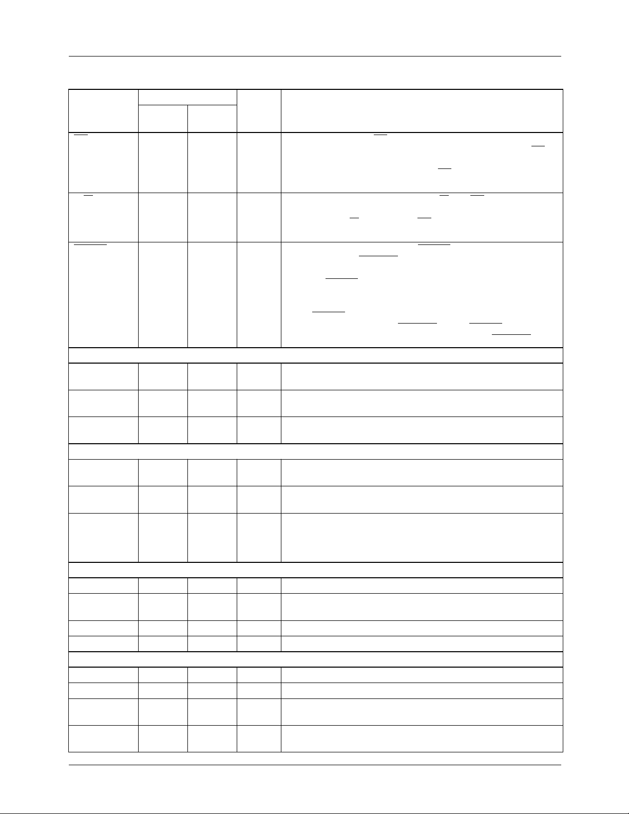
Pin Descriptions (continued)
Pin Number
84-Lead
Pin Name
CS 6 72 TTL Chip Select. When CS is HIGH, the microprocessor interface
R/W 7 73 TTL Bus Read/Write Control. When R/W and CS are LOW, the
RESET 5 71 TTL Master Reset Input. Bringing RESET LOW sets the software
Video Output
COMPOSITE 33 2 1 V
LUMA 35 5 1 V
CHROMA 37 8 1 V
Analog Interface
V
REF
COMP 39 10 0.1 µF Compensation Capacitor. Connection point for 0.1µf
R
REF
JTAG Test Interface
TDI 25 93 TTL Data Input Port. Boundary scan data input port.
TMS 24 92 TTL Scan Select Input. Boundary scan (HIGH)/normal operation
TCK 23 91 TTL Scan Clock Input. Boundary scan clock.
TDO 22 90 TTL Data Output Port. Boundary scan data output port.
Power Supply
V
DD
V
DDA
D
GND
PLCC
30 98 +1.23 V Voltage Reference Input. External voltage reference input,
31 99 392Ω Current-setting Resistor. Connection point for external
27, 64, 81 41, 62, 95 +5 V Positive digital power supply.
40-43 13-17 +5 V Positive analog power supply.
10, 26, 65, 8042, 61, 76, 940.0 V Digital Ground.
100-Lead
MQFP
Value Pin Function Description
port, D
LOW, the microprocessor can read or write parameters over
D
7-0
data to its assigned working registers.
microprocessor can write to the control registers or CLUT over
D
7-0
contents of any CLUT address or control register over D
reset control bit, SRESET, LOW, forcing the internal state
machines to their starting states and disabling all outputs.
Bringing RESET HIGH synchronizes the internal pixel clock
(PCK = PXCK / 2) to maintain a defined pipeline delay through
the TMC22x91. If HRESET is set HIGH, the encoder is enabled
when RESET goes HIGH. If HRESET is LOW, the host restarts
the TMC22x91 by setting SRESET HIGH. RESET does not
affect the CLUT or the control registers, except SRESET.
NTSC/PAL Video. Analog output of composite D/A converter,
P-P
nominally 1.35 volt peak-to-peak into a 37.5Ω load.
Luminance-only Video. Analog output of luminance D/A
P-P
converter, nominally 1.35 volt peak-to-peak into a 37.5Ω load.
Chrominance-only Video. Analog output of chrominance D/A
P-P
converter, nominally 1.35 volt peak-to-peak into a 37.5Ω load.
internal voltage reference output, nominally 1.235 V.
decoupling capacitor.
current-setting resistor for D/A converters. The resistor (392Ω)
is connected between R
are inversely proportional to the value of R
(LOW) selector.
, is set to HIGH impedance and ignored. When CS is
7-0
. One additional falling edge of CS is needed to move input
. When R/W is HIGH and CS is LOW, it can read the
REF
and A
. Output video levels
GND
REF
.
7-0
.
A
GND
32, 34, 36, 384, 6, 9,
100
0.0 V Analog Ground.
9
Page 10
PRODUCT SPECIFICATION TMC22091/TMC22191
Pin Descriptions (continued)
Pin Number
84-Lead
Pin Name
Test
TEST 28, 29,
NC N/A 1, 3, 7,
PLCC
48-51
100-Lead
MQFP
22-25,
96-97
11-12,
28-30,
52-55,
69, 78-79
Value Pin Function Description
0.0 V Factory testing (TMC22091 only). Reserved for factory
testing. These pins have no effect on the operation but do
function as JTAG registers. They should be grounded directly
or pulled down to ground with 1kΩ or smaller resistors.
No Connect
Control Registers
The TMC22x91 is initialized and controlled by a set of registers. The registers are organized into 13 categories:
1. Global Control
2. Format Control
3. Interface Control
4. Test Control
5. Key Control
6. Misc. Control
7. Standards Control
8. Layering Control (TMC22191)
9. Key Value
10. Timing
11. Subcarrier
12. Test I/O
13. Mask Register
An external controller loads the Control Registers through a
standard interface port. It also loads the CLUT and reads its
contents or those of the Control Registers. The port is
governed by pins CS, R/W, and A
The Address Register for the CLUT and the Control Register
pointer automatically increment to allow successive writes to
sequential addresses. In the CLUT, the Address Register has
two additional bits which increment in modulo-three to
sequentially access the red, green, and blue portions. All
three colors must be written when any CLUT address is
changed.
The control register autoincrement follows the sequence
indicated in the Control Register Map. When it reaches
address 40, it stops incrementing, allowing multiple reads or
writes of test data from/to the TESTDAT register. To exit the
test mode, reset the Control Register pointer by setting A
D
, and R/W LOW and then bring CS LOW. Address 1F is
7-0
a read-only status register. It is addressed by the autoincrement sequencer. Any data may be written into this port at
that time but it will not be stored. When address 50 is
accessed, no autoincrement takes place, allowing multiple
writes to the Mask Register.
1-0
.
1-0
,
10
Page 11
PRODUCT SPECIFICATION TMC22091/TMC22191
Table 2. Microprocessor Port Control
A
1-0
00 0 Write D
00 1 Read Control Register pointer
01 0 Write D
01 1 Read CLUT Address Pointer on
10 0 Write D
10 1 Read addressed Control
11 0 Write D
11 1 Read addressed CLUT location
R/W Action
pointer
on D
7-0
Pointer
D
7-0
Register
Register on D
location
on D
7-0
into Control Register
7-0
into CLUT Address
7-0
to addressed Control
7-0
7-0
to addressed CLUT
7-0
Table 3. Control Register Map
Reg Bit Name Function
Global Control Register
00 7-5 Reserved
00 4 SRESET Software reset
00 3 PAL Standard select, NTSC
or PAL
00 2 LUMDIS Luminance input disable
00 1 CHRDIS Chrominance input
disable
00 0 HRESET Software reset disable
Format Control Register
01 7 Reserved
01 6 LCREN Layering Control
Register enable
(TMC22191)
01 5 RAMPEN Modulated ramp test
01 4 CB Color bar test
01 3-2 FORMAT PD
select
01 1-0 INMODE PD
select
Interface Control Register
02 7 VITSEN VITS lines enable
02 6 SHCY Short-cycle test mode
02 5-4 TBASE Time-base source select
02 3 SOUT Sync output mode select
input format
23-0
input mode
23-0
Table 3. Control Register Map (continued)
Reg Bit Name Function
02 2 FBDIS Frame buffer signals
disable
02 1 PDCDIR PDC master, slave
select
02 0 FLDLK Field lock select
Test Control Register
03 7 Reserved
03 6 LIMEN Luminance limiter
enable
03 5 TESTEN Test enable
03 4 HOLDEN MSBs/LSBs hold select
03 3 TSTMSB LSBs, MSBs in/out
select
03 2 LUMTST LUMA channel test
03 1 8FSUBR 8-field subcarrier reset
enable
03 0 CHRTST CHROMA channel test
Key Control Register
04 7 Reserved
04 6 HKEN Hardware key enable
04 5 BUKEN Burst key enable
04 4 SKEXT Data key operation
select
04 3 DKDIS Green/red/Y data key
disable
04 2 EKDIS Blue/green/C
disable
04 1 FKDIS Red/blue/CR data key
disable
04 0 SKEN Data key enable
Layering Control Register (TMC22191)
04 7 LAYMODE MSB of Layer
Assignments select
04 6 HKEN Hardware key enable
04 5 BUKEN Burst key enable
04 4 SKEXT Data key operation
select
04 3-1 LAYMODE LSBs of Layer
Assignments select
04 0 SKEN Data key enable
Key Value Registers
05 7-0 DKEY Green/red/Y data key
value
06 7-0 EKEY Blue/green/CB data key
value
data key
B
11
Page 12
TMC22091/TMC22191 PRODUCT SPECIFICATION
Table 3. Control Register Map (continued)
Reg Bit Name Function
07 7-0 FKEY Red/blue/CR data key
value
08-0D Reserved
Misc. Control Register
0E 7 EFEN Register 0E and 0F
enable
0E 6 COMPD/A COMPOSITE D/A
disable
0E 5 SVIDD/A LUMA/CHROMA D/A
disable
0E 4 FKREN Luminance processing
enabled
0E 3 RATIO Luminance ratio select
0E 2 TFLK Luminance pass
threshold select
0E 1 T512 EH/SL offset select
0E 0 CB100 NTSC/PAL Color Bars
Standards Control Register
0F 7 EFEN Same as Reg 0E bit 7
but read-only
0F 6 SIX25 625/525 line per frame
select
0F 5 PALID Phase alternate line
select
0F 4 SETUP 7.5 IRE Pedestal Enable
0F 3-2 YGAIN Luminance gain settings
0F 1-0 CGAIN Chrominance gain
settings
Timing Registers
10 7-0 SY Horizontal sync tip
length
11 7-0 BR Breezeway length
12 7-0 BU Burst length
13 7-0 CBP Color back porch length
14 7-0 XBP Extended color back
porch 8 LSB
15 7-0 VA Active video 8 LSB
16 7-0 VC Active video start 8 LSB
17 7-0 VB Active video end 8 LSB
18 7-6 XBP Extended color back
porch 2 MSB
18 5-4 VA Active video 2 MSB
18 3-2 VC Active video start 2 MSB
18 1-0 VB Active video end 2 MSB
Table 3. Control Register Map (continued)
Reg Bit Name Function
19 7-0 FP Front porch length
1A 7-0 EL Equalization pulse LOW
length
1B 7-0 EH Equalization pulse HIGH
length
1C 7-0 SL Vertical sync LOW
length
1D 7-0 SH Vertical sync HIGH
length
1E 7-0 CBL Color bar length
1F 7-5 FIELD Field identification
1F 4-0 LTYPE Line type identification
Subcarrier Registers
20 7-0 FREQL Subcarrier frequency 4th
byte (LSBs)
21 7-0 FREQ3 Subcarrier frequency 3rd
byte
22 7-0 FREQ2 Subcarrier frequency
2nd byte
23 7-0 FREQM Subcarrier frequency 1st
byte (MSBs)
24 7-0 SYSPHL Video phase offset LSBs
25 7-0 SYSPHM Video phase offset
MSBs
26 7-0 BURPHL Burst phase offset LSBs
27 7-0 BURPHM Burst phase offset MSBs
28-3F Reserved
Test I/O Register
40 7-0 TESTDAT Test data input/output
Mask Register
50 7-0 MASK Mask register
Y-Component Register
60 7-0 Y Y-component input/
output
Notes:
1. Functions are listed in the order used for reading and
writing.
2. For each register listed above, all bits not listed are
reserved and should be set to zero to ensure proper
operation.
3. The meaning of Register 04 (Key Control Register/Layering Control Register) is determined by Format Control
Register bit 6 (TMC22191).
12
Page 13
PRODUCT SPECIFICATION TMC22091/TMC22191
Control Register Definitions
Global Control Register (00)
7 6 5 4 3 2 1 0
Reserved SRESET PAL LUMDIS CHRDIS HRESET
Reg Bit Name Function
00 7-5 Reserved.
00 4 SRESET Software reset. When LOW, resets and holds internal state machines and
disables outputs. When HIGH (normal), starts and runs state machines and
enables outputs.
00 3 PAL Video standard select. When LOW, the NTSC standard is generated with 7.5
IRE pedestal. When HIGH, PAL standard video is generated. This bit is ignored
if Register 0E bit 7 is HIGH, enabling the 0E and 0F registers.
00 2 LUMDIS Luminance input disable. When LOW (normal), luminance (Y) data from
external frame buffer is enabled. When HIGH, luminance (Y) data into the
TMC22x91 is forced to 0 IRE but sync pulses continue from the LUMA output.
00 1 CHRDIS Chrominance input disable. When LOW (normal), burst and frame buffer data
into the TMC22x91 are enabled. when HIGH, burst and frame buffer data are
suppressed, enabling monochrome operation.
00 0 HRESET Software reset enable. SRESET
LOW. State machines are reset and held. When HRESET is LOW, RESET may
be taken HIGH at any time. The TMC22x91 is enabled and a new frame is
begun with line 1, field 1 on the next PXCK after SRESET is set HIGH. The D/A
converters are powered down while RESET is LOW. When HRESET is HIGH,
a new frame is begun with line 1, field 1 on the next PXCK after RESET is taken
HIGH. SRESET is ignored. The D/A converters remain active during the reset
sequence.
is forced LOW when the RESET pin is taken
13
Page 14

TMC22091/TMC22191 PRODUCT SPECIFICATION
Control Register Definitions (continued)
Format Control Register (01)
7 6 5 4 3 2 1 0
Reserved LCREN RAMPEN CB FORMAT INMODE
Reg Bit Name Function
01 7 Reserved.
01 6 LCREN (TMC22191) Layering Control Register enable. When LOW, the Layering
Control Register is not available and Key Control Register functions are
enabled. In this mode, the TMC22191 functions like the TMC22091. When
HIGH, the Layering Control Register takes the place of the Key Control
Register and enables the layering functions. Data loaded into the Key or
Layering Control Registers will remain but have a different meaning if this bit is
changed.
01 5 RAMPEN Modulated ramp test. When LOW (normal), the TMC22x91 encodes and
outputs video corresponding to input data. When RAMPEN and CB
HIGH, an internally generated 40 IRE modulated ramp is produced, preempting
input data.
01 4 CB Color bar test. When HIGH (normal), the TMC22x91 encodes and outputs
video corresponding to input data. When CB, RAMPEN, and Format Control
Register bit 0 are LOW, internally generated color bars are produced,
preempting input data.
01 3-2 FORMAT PD
01 1-0 INMODE PD
When bits 3 and 2 are:
0 0 the CLUT output is interpreted as RGB and is converted to YCBCR.
0 1 is reserved. Bits 3 and 2 must be 00 or 10 when the Layering Control
Register is enabled (TMC22191).
1 0 the CLUT output is interpreted as GBR, and is converted to YCBCR.
1 1 the CLUT output is interpreted as YCBCR.
422, 15-bit, or 8-bit input modes.
input format select. Two bits select RGB, GBR, or YCBCR input data.
23-0
input mode select. These two bits set up the TMC22x91 for either 444,
23-0
are both
14
0 0 24-bit/pixel GBR, RGB, or YCBCR444 data enters from PD
0 1 YCBCR422 data enters from PD
1 0 15-bit/pixel GBR or RGB data from PD
1 1 8-bit/pixel color indexed data enters from PD
Bits 1 and 0 must be 00, 01, or 11 when the Layering Control Register is
enabled (TMC22191).
; CR and CB alternate from PD
23-8
14-0
7-0
.
23-0
15-8
Page 15
PRODUCT SPECIFICATION TMC22091/TMC22191
Control Register Definitions (continued)
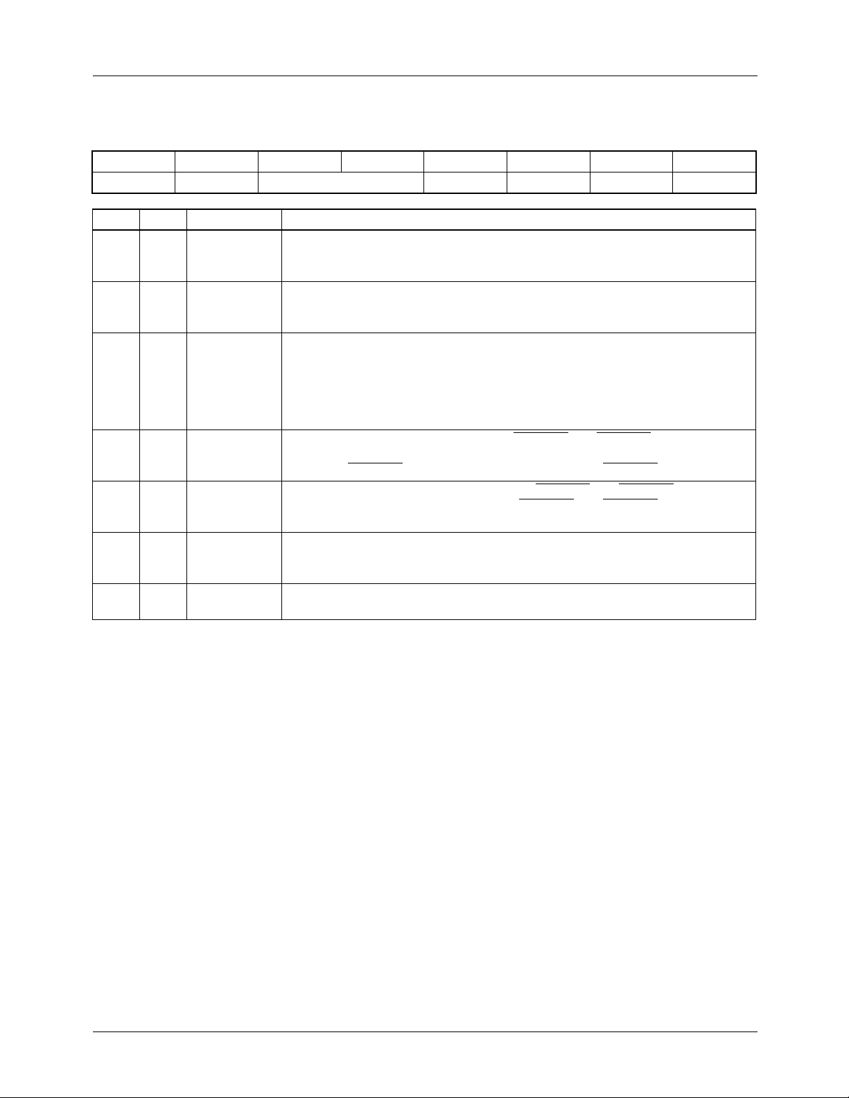
Interface Control Register (02)
7 6 5 4 3 2 1 0
VITSEN SHCY TBASE SOUT FBDIS PDCDIR FLDLK
Reg Bit Name Function
02 7 VITSEN VITS lines enable. When LOW, all UBB lines in the vertical interval are black
burst regardless of input data. When HIGH, all UBB lines in the vertical interval
become UVV active video and are dependent upon input data.
02 6 SHCY Short-cycle test mode. When LOW, normal operation is enabled. when HIGH,
EH (equalization pulse HIGH length) and SL (vertical sync LOW length) are
shortened by 256.
02 5-4 TBASE Time-base source select. These two bits set up the TMC22x91 for either
genlock or frame buffer control of timing. When bits 5 and 4 are:
0 0 the encoder counts out its own time-base from input clock PXCK.
0 1 the encoder locks to synchronizing signals from external genlock.
1 0 the encoder locks to synchronizing signals from frame buffer controller.
02 3 SOUT Sync output mode select. When LOW, VHSYNC
horizontal and vertical sync pulses. When HIGH, composite sync (H and V) is
output on VVSYNC while horizontal sync is output on VHSYNC.
02 2 FBDIS Frame buffer signals enable. When LOW, VVSYNC and VHSYNC outputs to
frame buffer are enabled. When HIGH, VVSYNC and VHSYNC outputs to
frame buffer are disabled.
02 1 PDCDIR PDC master/slave select. When LOW, PDC is an output where the encoder is
requesting data from the frame buffer. When HIGH, PDC is an input, and
directs the encoder to accept data from the frame buffer.
02 0 FLDLK Field lock select. When LOW, (in Slave mode) the encoder locks to each new
field. When HIGH, the encoder locks to field 1 only.
and VVSYNC output separate
15
Page 16

TMC22091/TMC22191 PRODUCT SPECIFICATION
Control Register Definitions (continued)
Test Control Register (03)
7 6 5 4 3 2 1 0
Reserved LIMEN TESTEN HOLDEN TSTMSB LUMTST 8FSUBR CHRTST
Reg Bit Name Function
03 7 Reserved.
03 6 LIMEN Luminance limiter enable. When LOW, all luminance values are passed to
modulator. when HIGH, luminance values are limited to 101 IRE.
03 5 TESTEN Test enable. When LOW, normal operation is enabled. When HIGH,
TESTDAT
D/A converters (WRITE) for test.
03 4 HOLDEN MSBs/LSBs hold select. When LOW, alternates MSBs and LSBs in test, at
PXCK rate. When HIGH, reads/writes only MSBS or LSBS in test (per
TSTMSB, bit 3)
03 3 TSTMSB LSBS,MSBS hold select. When LOW, connects 2 LSBs to TESTDAT
for testing when TESTEN is HIGH. When HIGH, connects 8 MSBs to
TESTDAT
03 2 LUMTST LUMA channel test. When LOW (normal), the luminance D/A converter is
driven from luminance channel. When HIGH, the luminance D/A converter is
driven from TESTDAT for testing when TESTEN is HIGH.
03 1 8FSUBR 8-field subcarrier reset enable. When LOW, the internal subcarrier generator is
03 0 CHRTST CHROMA channel test. When LOW (normal), the chrominance D/A converter is
reset with frequency and phase data from FREQ, SYSPH, and BURPH
registers every eight fields. When HIGH, the internal subcarrier generator freeruns on the basis of frequency and phase data from the last time it was reset.
When RESET goes LOW, the subcarrier frequency and phase will be reset
from FREQ, SYSPH, and BURPH after field 8.
driven from chrominance channel. When HIGH, the chrominance D/A converter
is driven from TESTDAT when TESTEN is HIGH.
(Register 40) is connected to the composite output (READ) and
7-0
1-0
for testing when TESTEN is HIGH.
7-0
16
Page 17

PRODUCT SPECIFICATION TMC22091/TMC22191
Control Register Definitions (continued)
Key Control Register (04)
7 6 5 4 3 2 1 0
Reserved HKEN BUKEN SKEXT DKDIS EKDIS FKDIS SKEN
Reg Bit Name Function
04 7 Reserved.
04 6 HKEN Hardware key enable. When LOW, the KEY input pin ignored. When HIGH, the
KEY input pin is enabled.
04 5 BUKEN Burst key enable. When LOW, output video burst is generated on TMC22x91.
When HIGH, output burst is taken from genlock input data.
04 4 SKEXT Data key operation select. When LOW, data keying is allowed only during
active video. When HIGH, keying is allowed during active video and blanking.
04 3 DKDIS Green/red/Y data key disable. When LOW, green/red/Y input data is enabled
for data keying. When HIGH, green/red/Y input data is ignored for data keying.
This function is enabled when Layering Control Register is enabled
(TMC22191).
04 2 EKDIS Blue/green/C
enabled for data keying. When HIGH, Blue/green/CB input data is ignored for
data keying. This function is enabled when Layering Control Register is
enabled (TMC22191).
04 1 FKDIS Red/blue/CR data key disable. When LOW, red/blue/CR input data is enabled
for data keying. When HIGH, red/blue/CR input data is ignored for data keying.
This function is enabled when Layering Control Register is enabled
(TMC22191).
04 0 SKEN Data key enable. When LOW, data keying is disabled. When HIGH, data keying
is enabled.
data key disable. When LOW, Blue/green/CB input data is
B
17
Page 18
TMC22091/TMC22191 PRODUCT SPECIFICATION
Control Register Definitions (continued)
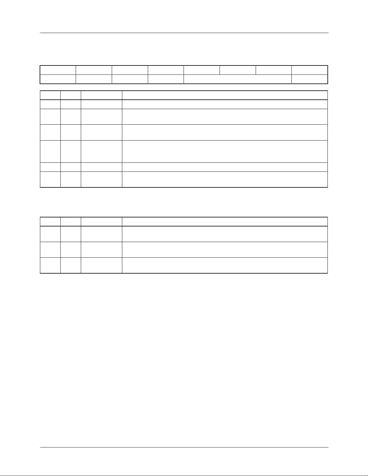
Layering Control Register (04) (TMC22191)
7 6 5 4 3 2 1 0
LAYMODE HKEN BUKEN SKEXT LAYMODE SKEN
Reg Bit Name Function
04 7 LAYMODE MSB of Layer Assignments select.
04 6 HKEN Hardware key enable. When LOW, the KEY input pin ignored. When HIGH, the
KEY input pin is enabled.
04 5 BUKEN Burst key enable. When LOW, output video burst is generated on TMC22191.
When HIGH, output burst is taken from genlock input data.
04 4 SKEXT Data key operation select. When LOW, data keying is allowed only during
active video. When HIGH, data keying is allowed during active video and
blanking.
04 3-1 LAYMODE Three LSBs of Layer Assignments select.
04 0 SKEN Data key enable. When LOW, data keying is disabled. When HIGH, data keying
is enabled.
Key Value Registers (05-07)
Reg Bit Name Function
05 7-0 DKEY Green/red/Y data key value. Eight bits hold the match value which triggers
keying on red/Y.
06 7-0 EKEY Blue/green/U data key value. Eight bits hold the match value which triggers
keying on green/U.
07 7-0 FKEY Red/blue/V key value. Eight bits hold the match value which triggers keying on
blue/V.
18
Page 19

PRODUCT SPECIFICATION TMC22091/TMC22191
Control Register Definitions (continued)
Miscellaneous Control Register (0E)
7 6 5 4 3 2 1 0
EFEN COMPD/A SVIDD/A FKREN RATIO TFLK T512 CB100
Reg Bit Name Function
0E 7 EFEN Register 0E and 0F enable. When LOW, the functions of Register 0E and 0F
are disabled. When HIGH, Registers 0E and 0F are active. When Registers 0E
and 0F are enabled, Register 00 bit 3 is ignored. Register 0E bit 7 will read back
whatever value was written.
0E 6 COMPD/A COMPOSITE D/A disable. When HIGH, the COMPOSITE D/A converter is
powered-down. When LOW, the D/A is enabled.
0E 5 SVIDD/A LUMA/CHROMA D/A disable. When HIGH, the LUMA and CHROMA D/A
converters are powered-down. When LOW, they are enabled.
0E 4 FKREN Luminance processing enable. When FKREN is HIGH, the KEY input defines
the function of CVBS input data. When the KEY input is HIGH, CVBS data is
keyed over PD input data. When KEY is LOW, CVBS data is assumed to be
luminance data delayed by one When FKREN is LOW, the KEY input operates
normally, switching between CVBS and PD data.
0E 3 RATIO Luminance ratio control bit. When LOW, 1/2 of current luminance and 1/2 of
field delayed luminance from the CVBS input are added to yield a new
combined luminance value. When RATIO is HIGH, 3/4 of current luminance is
added to 1/4 of the delayed luminance to produce a new luminance value.
0E 2 TFLK Luminance-pass threshold. The difference between current luminance and
delayed luminance (from the CVBS inputs) is compared against a preset
threshold set by TFLK. When TFLK is LOW, the high threshold must be
exceeded to trigger the combining of current and delayed luminance (according
to RATIO). If the higher threshold is not exceeded, current luminance is passed
without modification. When TFLK is HIGH, a lower threshold is used to trigger
the combining of current and delayed luminance.
0E 1 T512 EH/SL offset control bit. When LOW, the true value of EH and SL is offset by
256. When HIGH, the true value for EH and SL is offset by 512.
0E 0 CB100 NTSC/PAL color bars select. When HIGH, color bars with 100% white level are
selected. When LOW, color bars will have 75% white level.
19
Page 20

TMC22091/TMC22191 PRODUCT SPECIFICATION
Control Register Definitions (continued)
Standards Control Register (0F)
7 6 5 4 3 2 1 0
EFEN SIX25 PALID SETUP YGAIN CGAIN
Reg Bit Name Function
0F 7 EFEN Same as Register 0E bit 7, but read-only.
0F 6 SIX25 Select 625 lines per frame. When HIGH, the encoder assumes 625 line per
frame. When LOW, 525 lines per frame are assumed.
0F 5 PALID PAL select. When HIGH, Phase alternate line (PAL) operation is selected.
When LOW, operation conforms to NTSC standards.
0F 4 SETUP Setup enable. When HIGH, a 7.5 IRE Pedestal is added to the output video.
when LOW, no pedestal is added.
0F 3-2 YGAIN Luminance gain settings are adjusted to conform to the following NTSC and
PAL standards:
0 0 NTSC without SETUP
0 1 NTSC-A and PAL-M
1 0 PAL-I and PAL-N
1 1 Reserved
0F 1-0 CGAIN Chrominance gain settings are adjusted to conform to the following NTSC and
PAL standards:
0 0 NTSC without SETUP
0 1 NTSC-A and PAL-M
1 0 PAL-I and PAL-N
1 1 Reserved
Timing Registers (10-17)
Reg Bit Name Function
10 7-0 SY Horizontal sync tip length. This 8-bit register holds a value extending from 0 to
255 PCK cycles.
11 7-0 BR Breezeway length. This 8-bit register holds a value extending from 0 to 255
PCK cycles.
12 7-0 BU Burst length. This 8-bit register holds a value extending from 0 to 255 PCK
cycles.
13 7-0 CBP Color back porch length. This 8-bit register holds a value extending from 0 to
255 PCK cycles.
14 7-0 XBP Extended color back porch 8 LSBs. This 8-bit register holds the LSBs of a
10-bit value extending from 0 to 1023 PCK cycles. The two MSBs are located in
control register 18.
15 7-0 VA Active video 8 LSBs. This 8-bit register holds the LSBs of a 10-bit value
extending from 0 to 1023 PCK cycles. The two MSBs are located in control
register 18.
16 7-0 VC Active video start 8 LSBs. This 8-bit register holds the LSBs of a 10-bit value
which is the initial half active video length extending from 0 to 1023 PCK cycles.
The two MSBs are located in control register 18.
17 7-0 VB Active video end 8 LSBs This 8-bit register holds the LSBs of a 10-bit value
which is the end half active video length extending from 0 to 1023 PCK cycles.
The two MSBs are located in control register 18.
20
Page 21
PRODUCT SPECIFICATION TMC22091/TMC22191
Control Register Definitions (continued)
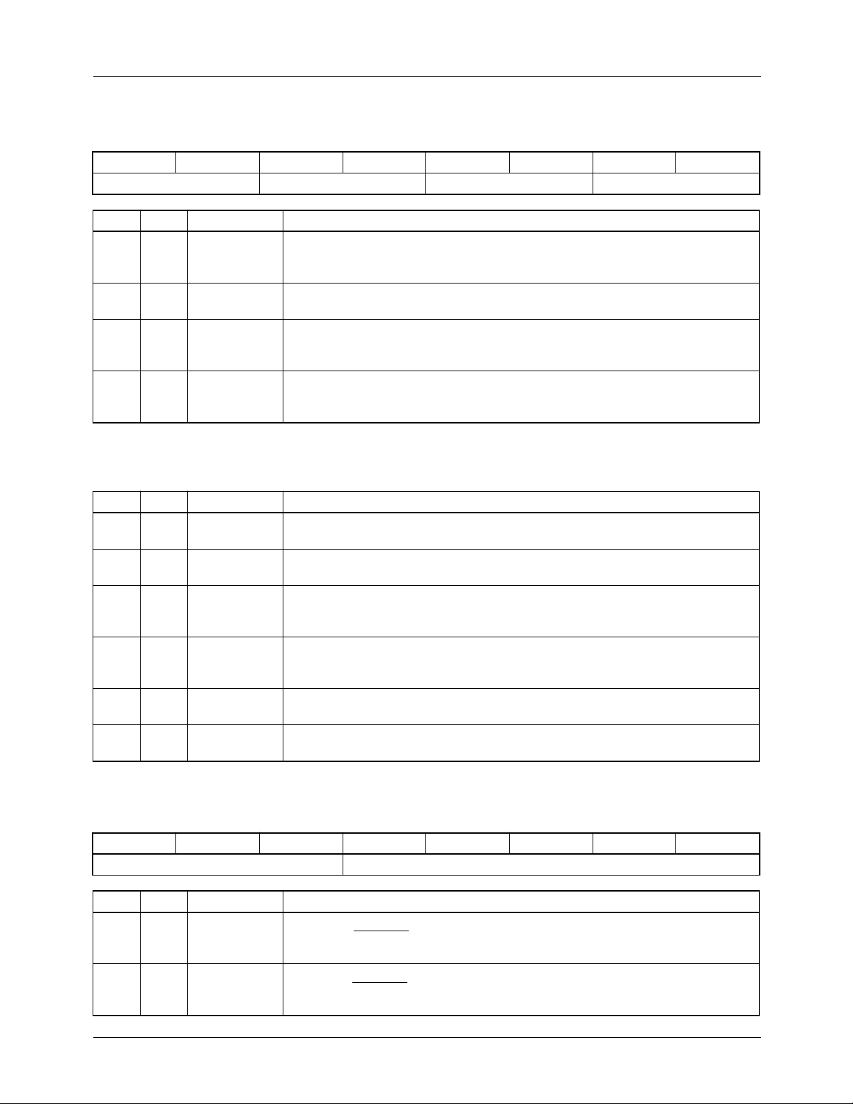
Timing Register (18)
7 6 5 4 3 2 1 0
XBP VA VC VB
Reg Bit Name Function
18 7-6 XBP Extended color back porch 2 MSBs. These two bits hold the MSBs of a 10-bit
value extending from 0 to 1023 PCK cycles. The LSBs are located in control
register 14.
18 5-4 VA Active video 2 MSB. These two bits hold the MSBs of a 10-bit value extending
from 0 to 1023 PCK cycles. The LSBs are located in control register 15.
18 3-2 VC Active video start 2 MSBs. These two bits hold the MSBs of a 10-bit value which
is the initial half active video length extending from 0 to 1023 PCK cycles. The
LSBs are located in control register 16.
18 1-0 VB Active video end 2 MSBs. These two bits hold the MSBs of a 10-bit value which
is the end half active video length extending from 0 to 1023 PCK cycles. The
LSBs are located in control register 17.
Timing Registers (19-1E)
Reg Bit Name Function
19 7-0 FP Front porch length. This 8-bit register holds a value extending from 0 to 255
PCK cycles.
1A 7-0 EL Equalization pulse LOW length. This 8-bit register holds a value from 0 to 255
PCK cycles.
1B 7-0 EH Equalization pulse HIGH length. This 8-bit register holds a value extending from
0 to 255 PCK cycles. This value, when added to 256 (or 512), determines the
final pulse length in the range of 256 to 511 (or 767) PCK cycles.
1C 7-0 SL Vertical sync LOW length. This 8-bit register holds a value from 0 to 255 PCK
cycles. This value, when added to 256 (or 512), determines the final pulse
length in the range of 256 to 511 (or 767) PCK cycles.
1D 7-0 SH Vertical sync HIGH length. This 8-bit register holds a value extending from 0 to
255 PCK cycles.
1E 7-0 CBL Color bar length. This 8-bit register holds a value which is the length of each
color bar displayed extending from 0 to 255 PCK cycles.
Timing Register (1F)
7 6 5 4 3 2 1 0
FIELD LTYPE
Reg Bit Name Function
1F 7-5 FIELD Field identification (read only). These three bits are updated 12 PXCK periods
after each VHSYNC. They allow the user to determine field type on a
continuous basis.
1F 4-0 LTYPE Line type identification (read only). These five bits are updates 5 PXCK periods
after each VHSYNC. They allow the user to determine line type on a continuous
basis.
21
Page 22
TMC22091/TMC22191 PRODUCT SPECIFICATION
Control Register Definitions (continued)
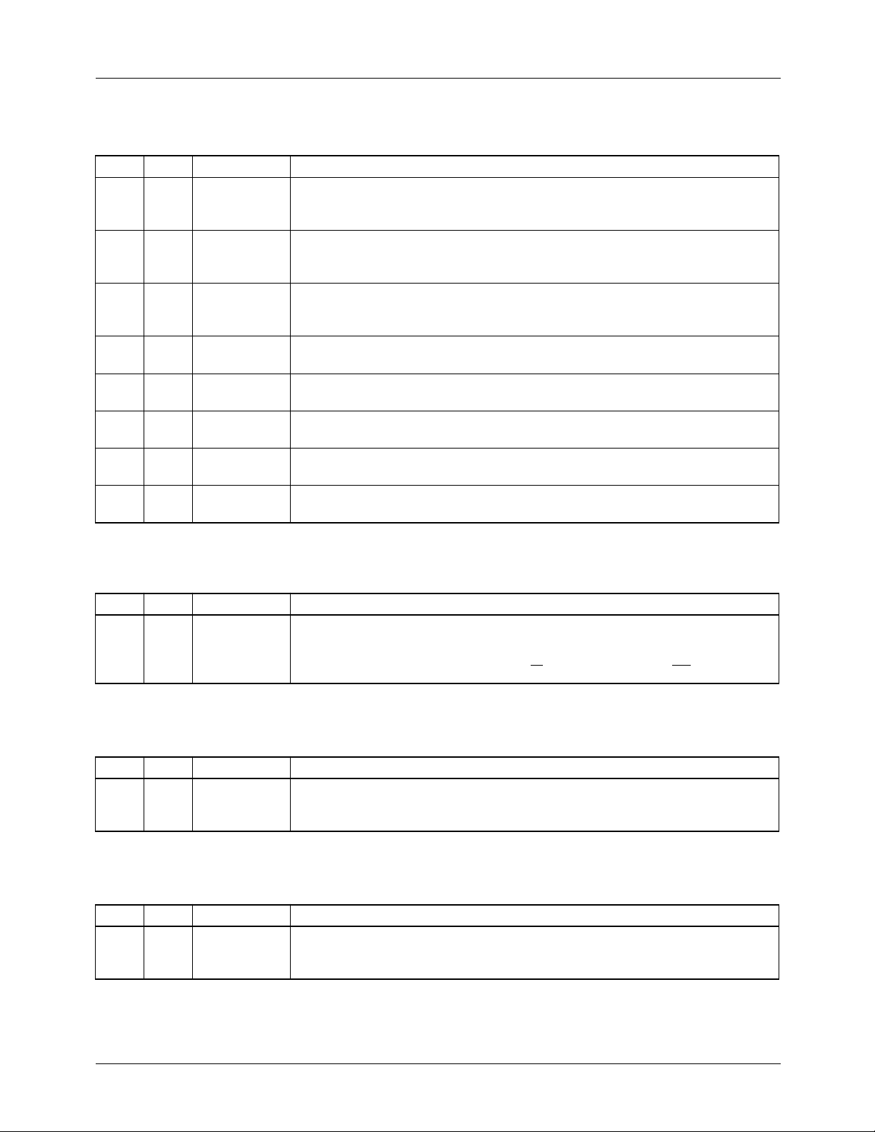
Subcarrier Registers (20-27)
Reg Bit Name Function
20 7-0 FREQL Subcarrier frequency 4th byte (LSBs). This 8-bit register holds the LSB (bits
7-0) of the 32-bit subcarrier frequency value (non-genlock modes). The next
eight most significant bits are held in Register 21.
21 7-0 FREQ3 Subcarrier frequency 3rd byte. This 8-bit register holds bits 15:8 of the
subcarrier frequency value (non-genlock modes). The next eight most
significant bits are held in Register 22.
22 7-0 FREQ2 Subcarrier frequency 2nd byte. This 8-bit register holds bits 23-16 of the
subcarrier frequency value (non-genlock modes). The eight MSBs are held in
Register 23.
23 7-0 FREQM Subcarrier frequency 1st byte (MSBs). This 8-bit register holds the MSBs (bits
31-24) of the 32-bit subcarrier frequency value (non-genlock modes).
24 7-0 SYSPHL Video phase offset LSBs. This 8-bit register holds the 8 LSBs of color subcarrier
phase offset during active video.
25 7-0 SYSPHM Video phase offset MSBs. This 8-bit register holds the 8 MSBs of color
subcarrier phase offset during active video.
26 7-0 BURPHL Burst phase offset LSBs. This 8-bit register holds the 8 LSBs of burst phase
offset for color adjustment.
27 7-0 BURPHM Burst phase offset MSBs. This 8-bit register holds the 8 MSBs of burst phase
for color adjustment.
Test I/O Register (40)
Reg Bit Name Function
40 7-0 TESTDAT Test data input/output. This 8-bit register holds MSBs or LSBs, as determined
by the Test Control Register. This control address does not auto-increment
during read or write operations. To exit the test mode, reset the Control
Register pointer by setting A
Mask Register (50)
Reg Bit Name Function
50 7-0 MASK Mask register. This 8-bit register holds an 8-bit word that is logically ANDed with
the incoming data presented to the three CLUTs in color-index mode. This
register is a write-only register.
Y-Component Register (60)
Reg Bit Name Function
60 7-0 Y Y-component register. This register holds the contents of the luminance value
before the Sync and Blank Insert circuitry of the encoder. Loading the Control
Register pointer with 60h brings 8-bit Y values out on the D
and R/W LOW and then bring CS LOW.
1-0
port.
7-0
22
Page 23
PRODUCT SPECIFICATION TMC22091/TMC22191
Color Lookup Table
The CLUT can be used in a variety of ways, depending on
the data format and source presented to the PD port.
The CLUT is loaded like a RAMDAC, sequentially writing
one byte to each of the three locations associated with the
selected CLUT address. These three locations are referred to
as T ables D, E, and F as shown in table 16 (not R,G, and B
because they may or may not contain RGB information). and
are loaded in that sequence. The address will increment automatically after the three values at one address are written or
read.
Color-index Modes
In color-index (CI) mode, the CLUT is used to store the
color look-up data, translating the 8-bit source pixel data into
24-bit RGB colors. Table D holds red data, Table E is green
data, and Table F holds blue Data. The incoming data are
presented to the three tables in parallel, and a 24-bit output is
produced.
When the encoder is connected in parallel with a RAMDAC
in a VGA system, the CLUT can be loaded simultaneously
with the CLUT in the output RAMDA C. If a 6-bit RAMD AC
is employed, 6 bits can be loaded via data pins D
justified). The two LSBs should be set to 00 for optimal
black level representation, but the lar gest error introduced by
extraneous data in the LSBs is 3/4 LSB (at 6 bits). The
encoder will produce the closest possible translation of the
VGA colors in the encoded video environment.
7-2
(MSB
GBR/RGB Modes
The nominal configuration for GBR/RGB modes is unity
gain (CLUT data = CLUT address) for PAL and NTSC.
Other transfer functions, such as gain adjustment, offset, and
gamma correction, are easily loaded. The color data is
loaded into the tables in G-B-R sequence in GBR mode, and
R-G-B sequence in RGB mode.
Luminance/Color Difference Modes
The TMC22x91 expects Y , B-Y, and R-Y signals at the input
to its modulator section. When presenting CCIR-601 YCBCR
or digitized Y, B-Y, R-Y data to the CLUT, gain and offset factors are needed. Table 4 specifies the recommended transfer
functions. The CLUT is loaded in Y-CB-CR sequence.
Overlay Operation
For the TMC22091 and TMC22191 (when Format Control
Register Bit 6 = LOW), the OL
CCIR-601 operation, the nominal data range for Y is from 16
to 235 and for CB and CR is from 16 to 240. This means that
CLUT locations 0 to 15 and 241 to 255 are available for
overlay colors. When the o verlay locations are addressed (by
forcing CLUT addresses outside the normal CCIR-601 data
range), the addressed CLUT data is encoded resulting in the
specific color found in that CLUT location. Overlay colors
information stored in the unused CLUT locations must be Y,
B-Y, R-Y values. Y, B-Y, and R-Y values are found from
RGB values by:
Y = 0.299 R + 0.587 G + 0.114 B
B-Y = -0.299 R – 0.587 G + 0.886 B
R-Y = 0.701 R – 0.587 G – 0.114 B
For the TMC22191, when the Format Control Register
Bit 6 = HIGH, Overlay is controlled by the OL
which directly access CLUT locations, 01 thru 0F and F1
thru FF, as shown in Table 5. The values stored in these
CLUT locations must be in RGB format.
inputs are inactive. In
4-0
4-0
inputs
Table 4. CLUT Transfer Functions for NTSC and PAL
Input Format (CLUT Address)
Component Data Range Component Data Range
R 0 to 255 R0=R R
G 0 to 255 G0=G G
B 0 to 255 B0=B B
Y 16 to 235 YO = Y * 1.1644 – 18.63 Y
C
B
C
R
Y 0 to 255 Y0=Y Y
B-Y ±127 (B-Y)
R-Y ±127 (R-Y)O = (R-Y) * 0.7065 (R-Y)
±112 (B-Y)O = CB * 1.0126 (B-Y)
±112 (R-Y)O = CR * 0.8011 (R-Y)
Transfer Equations
= (B-Y) * 0.893 (B-Y)
O
Output Format (CLUT Data)
O
O
O
O
O
O
O
O
O
0 to 255
0 to 255
0 to 255
0 to 255
0 to 255
±113
±90
±113
±90
23
Page 24
TMC22091/TMC22191 PRODUCT SPECIFICATION
Table 5. CLUT Locations Addressed by
Overlay Inputs (TMC22191)
OL4-0 CLUT location
00 No Overlay
01 01
02 02
•
•
0E 0E
0F 0F
10 No Overlay
11 F1
12 F2
•
•
•
•
•
•
Table 5. CLUT Locations Addressed by
Overlay Inputs (TMC22191)
OL
4-0 CLUT location
1E FE
1F FF
Color-space Conversion in the Matrix
When the input pixels are in RGB, GBR, or color-index format and the CLUT is bypassed (TMC22191), the Matrix
remains enabled, converting RGB data to color-difference
format. When the input pixels are in 444 format
(YC
verts 422 to 444) is not active. When the input pixels are in
YCBCR format, the CLUT is enabled to scale the data to
color-difference values and the Matrix is inactive. In colorindex mode, the Matrix is active, converting the RGB CLUT
output data to color-difference values.
444, RGB, GBR, CI), the Interpolator (which con-
BCR
Table 6. Pixel Input Operation for Format Control Register bit 6 = HIGH (TMC22191)
Format Control Register Pixel Data Format
FORMAT
Bit 3,2
00 (RGB) 00 (444) RGB YCBCR444
00 01 (422) RGB YCBCR422
00 10 (15-bit) RGB RGB15
00 11 (CI) RGB CI
01 xx reserved reserved
10 (GBR) 00 (444) GBR YCBCR444
10 01 (422) GBR YC
10 10 (15-bit) GBR GBR15
10 11 (CI) GBR CI
11 xx not allowed not allowed
INMODE
Bit 1,0
BYPASS = LOW
CLUT bypassed
(continued)
BYPASS = HIGH
CLUT enabled
422
BCR
Format Control Register Bit 6 = HIGH Format Control Register Bit 6 = LOW
MSB
23
Pixel 1
Pixel 2
Pixel 3
Pixel 4
Pixel n
Pixel n+1
Note: The pixel input sequence begins on the first LDV pulse after PDC goes HIGH. n = Odd number
Y
Y
Y
Y
Y
Y
n+1
15 8 7
16
1
2
3
4
n
C
B1
C
B1
C
B3
C
B3
C
Bn
C
Bn
Figure 2. Pixel Data (PD
LSB
0
C
R1
C
R1
C
R3
C
R3
C
Rn
C
Rn
Pixel n+1
) Sequence for YCBCR422
23-0
Pixel 1
Pixel 2
Pixel 3
Pixel 4
Pixel n
MSB
23
15 8 7
16
Y
1
Y
2
Y
3
Y
4
Y
n
Y
n+1
C
B1
C
R1
C
B3
C
R3
C
Bn
C
Rn
24
LSB
27003A
0
Page 25
PRODUCT SPECIFICATION TMC22091/TMC22191
Gamma Correction
Gamma is built into broadcast television systems as a correction factor for nonlinearity in image acquisition (nonlinear
conversion of light into current in a vidicon) and at the display (phosphor nonlinearity in converting current into light).
A Gamma corrector transfer function takes the form of
Output = k ( Input )
where a typical Gamma is 2.2 for NTSC, 2.8 for PAL.
Computer systems usually ignore Gamma in driving a display monitor. Each R, G, and B channel is treated as linear.
When encoding a computer display output to video, the user
must decide whether to apply a gamma correction factor and,
if so, what value. It is a good assumption that, since the digital video input over the CVBS bus is in composite form, it
has been Gamma corrected.
Gamma correction is applied in the RGB domain. When
operating in YC
601 signal, Gamma should have already been applied.
Gamma correction is readily added to the RGB transfer
equations shown in Table 4.
1/γ
, for example when encoding a CCIR-
BCR
Video Timing
The TMC22x91 can be programmed to accommodate a wide
range of system timing requirements. With a line locked
pixel rate of 10 to 15 Mpps, the digitally synthesized horizontal waveforms and subcarrier frequency and phase are
determined from 24 registers that are loaded by a controller.
Horizontal Programming
Horizontal interval timing is fully programmable, and is
established by loading the timing registers with the durations
of each horizontal element. The duration is expressed in
PCK clock cycles. In this way, any pixel clock rate between
10 MHz and 15 MHz can be accommodated, and any desired
standard or non-standard horizontal video timing may be
produced. Figure 3 illustrates the horizontal blanking interval with timing register identification.
Horizontal timing parameters can be calculated as follows:
t = N x (PCK period)
= N x (2 x PXCK period)
where N is the value loaded into the appropriate timing reg-
ister, and PCK is the pixel clock period.
Table 7. Horizontal Timing Specifications
NTSC-M
Parameter
FP 1.5 1.65 1.9
SY 4.7 4.7 4.95
BR 0.6 0.9 0.9
BU 2.5 2.25 2.25
CBP 1.6 2.55 1.8
VA 52.6556 51.95 51.692
H 63.5556 64.0 63.492
(µs)
PAL-I
(µs)
PAL-M
(µs)
Vertical Programming
Vertical interval timing is also fully programmable, and is
established by loading the timing registers with the durations
of each vertical timing element, the duration expressed in
PCK clock cycles. In this way as with horizontal programming, any pixel rate between 10 and 15 Mpps can be accommodated, and any desired standard or non-standard vertical
video timing may be produced.
Like horizontal timing parameters, vertical timing parameters are calculated as follows:
t = N x (PCK period)
= N x (2 x PXCK period)
where N is the value loaded into the appropriate timing register, and PCK is the pixel clock period.
The Vertical Interval comprises several different line types
based upon H, the Horizontal line time.
H = (2 x SL) + (2 x SH) [Vertical sync pulses]
= (2 x EL) + (2 x EH) [Equalization pulses]
The VB and VC lines are added to produce the half-lines
needed in the vertical interval at the beginning and end of
some fields. These must properly mate with components of
the normal lines.
VB= CBP + VA - XBP = H/2 – CBPVC
= VA – (EL + EH) = VA – H/2
where Equalization HIGH and LOW pulses (EL + EH) = H/2
and the Extended Color Back Porch, XBP = VA + CBP –VB.
XBP begins after the end of burst, BU, taking the place of
CBP in vertical interval UBV lines. Figure 5 shows the v ertical sync and equalization pulse detail
Horizontal timing resolution is two PXCK periods. PXCK
must be chosen such that it is an even integer multiple of the
horizontal line frequency. This ensures that the horizontal
line period, H, contains an integer number of pixels. The horizontal line comprises the sum of appropriate elements.
H = FP + SY + BR + BU + CBP + VA
When programming horizontal timing, subtract 5 PCK
periods from the calculated values of CBP and add 5 PCK
periods to the calculated value for VA.
Table 8. Vertical Timing Specifications
Parameter
(µs)
H 63.5556 64 63.492
EH 29.4778 29.65 29.45
EL 2.3 2.35 2.3
SH 4.7 4.7 4.65
SL 27.1 27.3 27.1
NTSC-M
(µs)
PAL-I
(µs)
PAL-M
(µs)
25
Page 26
TMC22091/TMC22191 PRODUCT SPECIFICATION
H
H/2
Burst
EH SL
VA FP FP VA
SY BU
FP
24318B
SHEL
24319A
Figure 3. Horizontal Blanking Interval Timing Figure 4. Sync and Equalization Pulse Detail Timing
VHSYNC
VVSYNC
524
523
UVV UVV
FIELDS 1 AND 3
3H
1 2 3 4 5 6 7 8 9 10
EE EE EE SS SS SS EE EE EE UBB
VERTICAL BLANKING
VERTICAL SYNC POST-EQUALIZATIONPRE-EQUALIZATION
3H 3H
19 20
22
21
UVVUBBUBB UVV
COMPOSITE
SYNC
VHSYNC
VVSYNC
COMPOSITE
SYNC
263262
UVV UVE
FIELDS 2 AND 4
273272271270269268267266265264
EE EE ES SS SS SE EE EE EB UBB
Figure 5. NTSC Vertical Interval
282
284283
285
UVVUBVUBB UVV
27000A
26
Page 27
PRODUCT SPECIFICATION TMC22091/TMC22191
Table 9. NTSC Field/Line Sequence and Identification
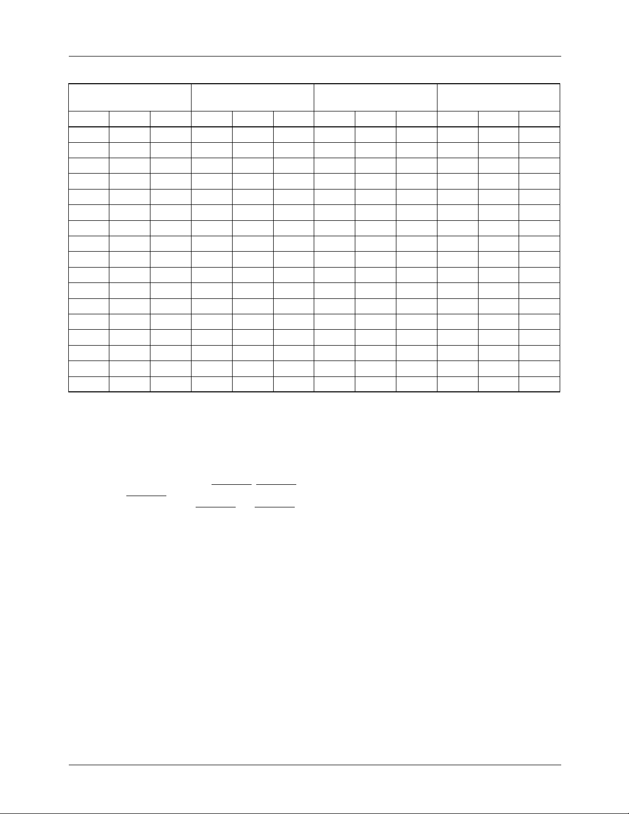
Field 1
FIELD ID = x00
Line ID LTYPE Line ID LTYPE Line ID LTYPE Line ID LTYPE
1 EE 00 264 EE 00 1 EE 00 264 EE 00
2 EE 00 265 EE 00 2 EE 00 265 EE 00
3 EE 00 266 ES 01 3 EE 00 266 ES 01
4 SS 03 267 SS 03 4 SS 03 267 SS 03
5 SS 03 268 SS 03 5 SS 03 268 SS 03
6 SS 03 269 SE 02 6 SS 03 269 SE 02
7 EE 00 270 EE 00 7 EE 00 270 EE 00
8 EE 00 271 EE 00 8 EE 00 271 EE 00
9 EE 00 272 EB 10 9 EE 00 272 EB 10
10 UBB 0D 273 UBB 0D 10 UBB 0D 273 UBB 0D
••• ••• ••• ••• ••• ••• ••• ••• ••• ••• ••• •••
20 UBB 0D 282 UBB 0D 20 UBB 0D 282 UBB 0D
21 UVV 0F 283 UBV 0E 21 UVV 0F 283 UBV 0E
22 UVV 0F 284 UVV 0F 22 UVV 0F 284 UVV 0F
••• ••• ••• ••• ••• ••• ••• ••• ••• ••• ••• •••
262 UVV 0F 524 UVV 0F. 262 UVV 0F 524 UVV 0F
263 UVE 0C 525 UVV 0F 263 UVE 0C 525 UVV 0F
EE Equalization pulse SE Half-line vertical sync pulse, half-line equalization pulse
SS Vertical sync pulse ES Half-line equalization pulse, half-line vertical sync pulse
EB Equalization broad pulse UBB Black burst
UVV Active video UVE Half-line video, half-line equalization pulse
UBV Half-line black, half-line video
Field 2
FIELD ID = x01
Field 3
FIELD ID = x10
Field 4
FIELD ID = x11
Master and Genlock mode details of VHSYNC, VVSYNC,
and composite VVSYNC (SOUT = HIGH) outputs are
shown in Figures 5 and 6. When VHSYNC and VVSYNC
are used as inputs (Slave mode), their falling edges mark the
beginning of the sync interval and the width of the input
pulse is specified under Operating Conditions.
27
Page 28
TMC22091/TMC22191 PRODUCT SPECIFICATION
12481247
UVV VE
VHSYNC
VVSYNC
COMPOSITE
SYNC
309 310
UVV VV
VHSYNC
VVSYNC
COMPOSITE
SYNC
623622
FIELDS 1 AND 5
22765432112501249
EE EE SS SS SE EE EE BB UBB UBB
FIELDS 2 AND 6
311 312 313 314 315 316 317 318 319 320
EE EE ES SS SS EE EE EB UBB UBB
FIELDS 3 AND 7
647632631630629628627626625624
23
334 335
648
2524
UVVUBVUBB UVV
336
UVVUBVUBB UVV
650649
651
26
337
VHSYNC
VVSYNC
COMPOSITE
SYNC
VHSYNC
VVSYNC
COMPOSITE
SYNC
UVV VE
934 935
UVV UV
EE EE SS SS SE EE EE UBB UBB UBB
FIELDS 4 AND 8
936 937 938 939 940 941 942 943 944 945
EE EE ES SS SS EE EE EB BB UBB
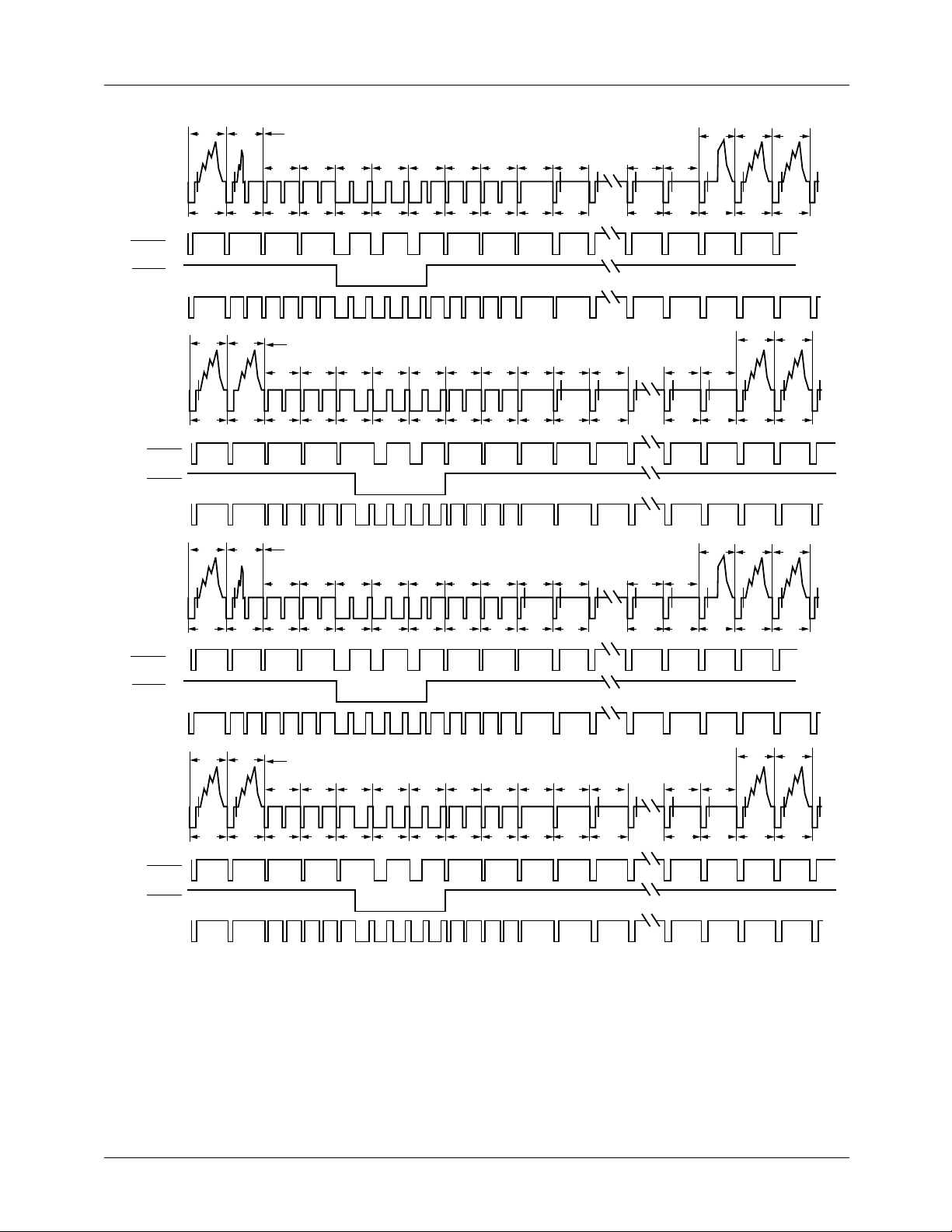
Figure 6. PAL Vertical Interval
959 960
UVVUBVUBB UVV
961
UVVUBVUBB UVV
962
27001A
28
Page 29

PRODUCT SPECIFICATION TMC22091/TMC22191
Table 10. PAL Field/Line Sequence and Identification
Field 1
FIELD ID = 000, 100
Line ID LTYPE Line ID LTYPE Line ID LTYPE Line ID LTYPE
1 SS 03 313 ES 01 626 SS 03 938 ES 01
2 SS 03 314 SS 03 627 SS 03 939 SS 03
3 SE 02 315 SS 03 628 SE 02 940 SS 03
4 EE 00 316 EE 00 629 EE 00 941 EE 00
5 EE 00 317 EE 00 630 EE 00 942 EE 00
6 -BB 05 318 EB 10 631 UBB 0D 943 EB 10
7 UBB 0D 319 UBB 0D 632 UBB 0D 944 -BB 05
8 UBB 0D 320 UBB 0D 633 UBB 0D 945 UBB 0D
••• ••• ••• ••• ••• ••• ••• ••• ••• ••• ••• •••
22 UBB 0D 335 UBB 0D 647 UBB 0D 960 UBB 0D
23 UBV 0E 336 UVV 0F 648 UBV 0E 961 UVV 0F.
24 UVV 0F 337 UVV 0F 649 UVV 0F 962 UVV 0F
••• ••• ••• ••• ••• ••• ••• ••• ••• ••• ••• •••
308 UVV 0F 621 UVV 0F 933 UVV 0F 1246 UVV 0F
309 UVV 0F 622 -VV 07 934 UVV 0F 1247 UVV 0F
310 -VV 07 623 -VE 04 935 UVV 0F 1248 -VE 04
311 EE 00 624 EE 00 936 EE 00 1249 EE 00
312 EE 00 625 EE 00 937 EE 00 1250 EE 00
Field 2
FIELD ID = 001, 101
Field 3
FIELD ID = 010, 110
Field 4
FIELD ID = 011, 111
EE Equalization pulse SE Half-line vertical sync pulse, half-line equalization pulse
SS Vertical sync pulse ES Half-line equalization pulse, half-line vertical sync pulse
EB Equalization broad pulse UBB Black burst
-BB Black burst with color burst suppressed UVV Active video
-VV Active video with color burst suppressed UVE Half-line video, half-line equalization pulse
-VE Half-line video, half-line equalization UBV half-line black, half-line video
pulse, color burst suppressed.
29
Page 30
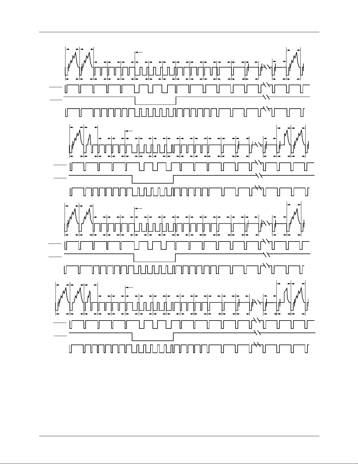
TMC22091/TMC22191 PRODUCT SPECIFICATION
VHSYNC
VVSYNC
COMPOSITE
SYNC
VHSYNC
VVSYNC
COMPOSITE
SYNC
522521
UVV UVV
259 260
UVV VE
521 522
FIELDS 1 AND 5
EE EE EE SS SE SS EE EE EE BBBB
FIELDS 2 AND 6
261 262 263 264 265 266 267 268 269 270
EE EE ES SS SS SE EE EE EB BB
FIELDS 3 AND 7
523 524 525 1 2 3 4 5 6 7
86 754321525524523
9
271
8
279
9
17
UBBUBB UVV
280
UVVUBVUBB UVV
17
18
281
18
VHSYNC
VVSYNC
COMPOSITE
SYNC
VHSYNC
VVSYNC
COMPOSITE
UVV VV
258 259
UVV UV
SYNC
EE EE EE SS SS SS EE EE EE BB
260
261 262 263 264 265 266 267 268 269
VE EE EE ES SS SS SE EE EE EB
FIELDS 4 AND 8
Figure 7. PAL-M Vertical Interval
270
271
UBBUBBUBB UVV
280
279
UBBUBBBB UVVUBV
281
27082A
30
Page 31

PRODUCT SPECIFICATION TMC22091/TMC22191
Table 11. PAL-M Field/Line Sequence and Identification
Field 1
FIELD ID = 000, 100
Line ID LTYPE Line ID LTYPE Line ID LTYPE Line ID LTYPE
1 SS 03 263 ES 01 1 SS 03 263 ES 01
2 SS 03 264 SS 03 2 SS 03 264 SS 03
3 SS 03 265 SS 03 3 SS 03 265 SS 03
4 EE 00 266 SE 02 4 EE 00 266 SE 02
5 EE 00 267 EE 00 5 EE 00 267 EE 00
6 EE 00 268 EE 00 6 EE 00 268 EE 00
7 -BB 05 269 EB 10 7 -BB 05 269 EB 10
8 -BB 05 270 -BB 05 8 UBB 05 270 -BB 05
9 UBB 0D 271 UBB 1D ••• ••• ••• 271 UBB 1D
••• ••• ••• ••• ••• ••• 17 UBB 0D. ••• ••• •••
17 UBB 0D 279 UBB 0D 18 UVV 0F 279 UBB 0D
18 UVV 0F 280 UBV 0E. ••• ••• ••• 280 UBV 0E.
··· ··· ··· 281 UVV 0F 258 UVV 0F 281 UVV 0F
259 UVV 0F ••• ••• ••• 259 -VV 07 ••• ••• •••
260 -VE 04 521 UVV 0F 260 -VE 04 521 UVV 0F
261 EE 00 522 -VV 07 261 EE 00 522 UVV 0F
262 EE 00 523 EE 00. 262 EE 00 523 EE 00
524 EE 00 524 EE 00
525 EE 00 525 EE 00
Field 2
FIELD ID = 001, 111
Field 3
FIELD ID = 010, 110
Field 4
FIELD ID = 011, 111
EE Equalization pulse SE Half-line vertical sync pulse, half-line equalization pulse
SS Vertical sync pulse ES Half-line equalization pulse, half-line vertical sync pulse
EB Equalization broad pulse UBB Black burst
-BB Black burst with color burst suppressed UVV Active video
-VV Active video with color burst suppressed UVE Half-line video, half-line equalization pulse
-VE Half-line video, half-line equalization UBV half-line black, half-line video
pulse, color burst suppressed.
31
Page 32

TMC22091/TMC22191 PRODUCT SPECIFICATION
Table 12. Standard Timing Parameters
Field
Horizontal
Standard
NTSC sqr.
pixel
NTSC
CCIR-601
NTSC 4x
F
PAL sqr.
pixel
PAL
CCIR-601
PAL 15
Mpps
PAL-M
sqr.pixel
PAL-M
CCIR-601
PAL-M 4x
F
Notes:
1. XBP, VA, VC, and VB are 10-bit values. The 2 MSBs for these four variables are in Timing Register 18. See Table 3.
2. EH and SL are 9-bit values. A most significant "1" is forced by the TMC22x91 since EH and SL must range from 256 to 511.
EH and SL may be extended to 767. Only the eight LSBs are stored in Timing Registers 1B and 1C.
3. Every calculated timing parameter has a minimum value of 5 except EH and SL which have minimum values of 256.
Rate
(Hz)
59.94 15.734266 12.27 24.54 3A 07 1F 0F 23 8B 05 77 65 12 1C 6A 4C 3A 52
59.94 15.734266 13.50 27.00 40 08 22 13 3F CA 1D 9D 65 13 1F 8E 6E 3F 59
59.94 15.734266 14.32 28.64 43 09 24 12 54 F7 30 B5 65 15 21 A6 84 43 5F
SC
50.00 15.625000 14.75 29.50 45 0D 21 21 6D 03 2B B7 75 19 23 B5 93 45 61
50.00 15.625000 13.50 27.00 40 0C 1E 22 4D BE 0E 93 65 16 20 90 71 3F 58
50.00 15.625000 15.00 30.00 46 0D 22 21 73 11 31 BF 75 19 23 BD 9A 47 62
60.00 15.750000 12.50 25.01 3E 0B 1C 13 26 86 FE 8B 61 18 1D 70 53 3A 52
60.00 15,750000 13.50 27.00 44 0C 1E 13 26 Bf 12 99 65 1A 1F 8E 6E 3F 57
60.00 15,750000 14.30 28.60 47 0D 20 15 4C E8 22 AC 65 1B 21 A5 84 42 5D
SC
Freq.
(kHz)
Pixel
Rate
(Mpps)
PXCK
Freq.
(MHz)
SY10BR11BU12CBP13XBP14VA15VC16VB17Note 118FP19EL1AEH
Timing Register (hex)
1B
2
SL
1CSH1D
2
CBL
1E
VITS Insertion
In both NTSC and PAL, the TMC22x91 can be set up to
allow Vertical Interval Test Signals (VITS) in the vertical
interval in place of normal black burst lines (UBB). This is
controlled by Interface Control Register bit 7. If this bit is
LOW, UBB lines are black burst and are independent of
TMC22x91 input data. If the bit is HIGH, all vertical interval
UBB lines become UVV. UVV lines are active video and
depend upon data input to the TMC22x91. VITS lines may
carry special test signals or pass captioning data through the
encoder.
Edge Control
SMPTE 170M NTSC and Report 624 PAL video standards
call for specific rise and fall times on critical portions of the
video waveform. The TMC22x91 does this automatically.
The TMC22x91 digitally defines slopes compatible with
SMPTE 170M NTSC or CCIR Report 624 PAL on:
1. H and V Sync leading and trailing edges.
2. Burst envelope.
3. Active video leading and trailing edges.
Subcarrier Programming
The color subcarrier is produced by an internal 32-bit digital
frequency synthesizer which is completely programmable in
frequency and phase. Separate registers are provided for phase
adjustment of the color burst and of the active video, permitting external delay compensation and color adjustment.
In Master or Slave mode, the subcarrier is internally synchronized to establish and maintain a specified relationship
between the falling edge of horizontal sync and color burst
phase (SCH). In NTSC and PAL, SCH synchronization is
performed every eight fields, on field 1 of the eight-field
sequence. Proper subcarrier phase is maintained through the
entire eight fields, including the 25 Hz offset in PAL
systems. See the description of 8FSUBR under Test Control
Register bit 1 for the subcarrier reset function.
In Genlock mode, the phase and relative frequency of the
incoming video are transmitted by the TMC22071 Genlocking Video Digitizer over the CVBS bus at the beginning of
each line, which synchronize the digital subcarrier synthesizer. When key control register bit BUKEN is HIGH and
digitized burst from the TMC22071 is passed through to the
reconstruction D/A converter , the reference subcarrier for the
chrominance modulator is still synthesized within the
encoder.
32
Page 33
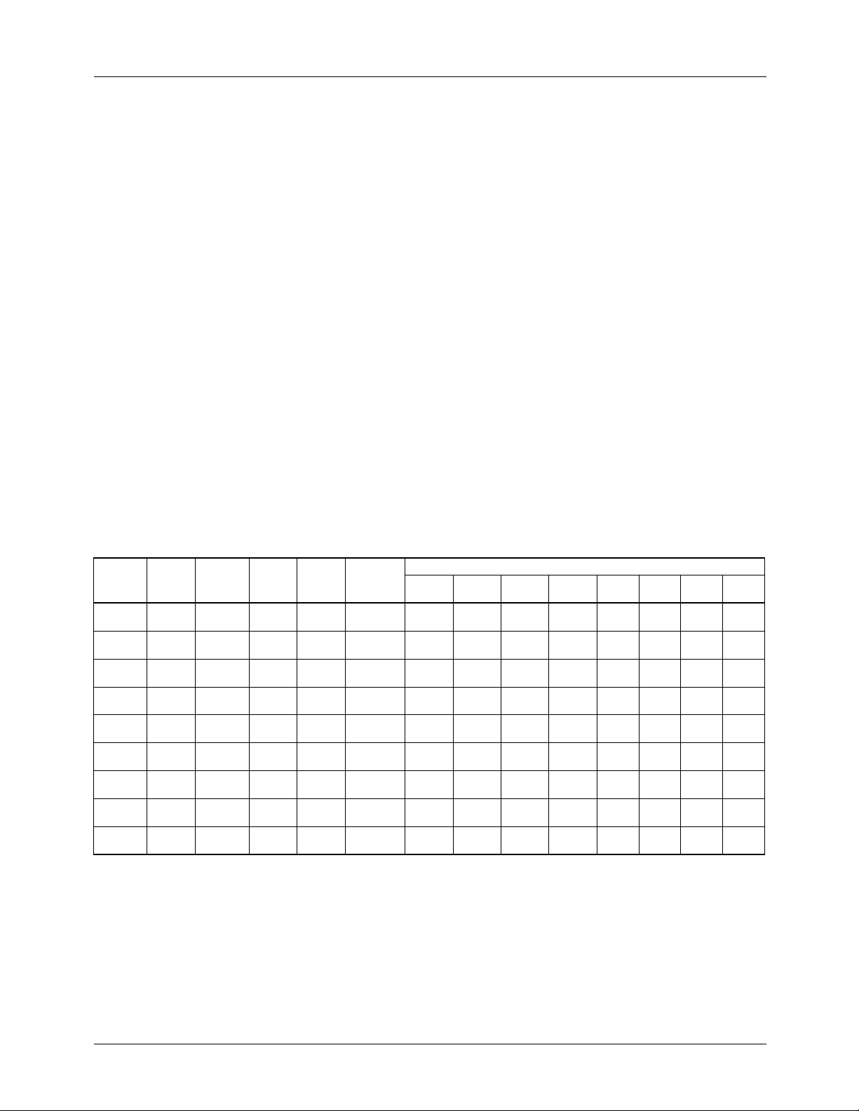
PRODUCT SPECIFICATION TMC22091/TMC22191
NTSC Subcarrier
For NTSC encoding, the subcarrier synthesizer frequency
has a simple relationship to the pixel clock period, repeating
over 2 lines: The decimal value is:
455 2⁄( )
FREQ
This value must be converted to binary and split into four
8-bit registers, FREQM, FREQ2, FREQ3, and FREQL. The
number of pixels/line is:
Pixels/line = (2/PXCK frequency) (H period)
SYSPH establishes the appropriate phase relationship
between the internal synthesizer and the chroma modulator.
The nominal value for SYSPH is zero.
Other values for SYSPH must be converted to binary and
split into two 8-bit registers, SYSPHM and SYSPHL.
Burst Phase (BURPH) sets up the correct relative NTSC
modulation angle. The value for BURPH is:
BURPH = SYSPH + 8,192
This value must be converted to binary and split into two
8-bit registers, BURPHM and BURPHL. The decimal number 8,192 advances the burst phase by 45°.
-----------------------------
pixels/line( )
232×=
PAL Subcarrier
The PAL relationship is more complex, repeating only once
in 8 fields (the well-known 25 Hz offset):
FREQ
1135 4⁄( ) 1 625⁄( )+
---------------------------------------------------
pixels/line( )
32
2
×=
This value must be conv erted to binary and split as described
previously for NTSC.
For PAL, the decimal value for SYSPH is found from:
SYSPH
FREQ
---------------- BURPH= =
17
2
This value must be converted to binary and split into two
8-bit registers, SYSPHM and SYSPHL. Burst Phase in PAL
is identical to SYSPH. Therefore, the same values for
SYSPHM and SYSPHL must be used for BURPHM and
BURPHL.
PAL-M Subcarrier
FREQ
SYSPH
909 4⁄( )
-----------------------------
pixels/line( )
FREQ
---------------- BURPH= =
17
2
32
×=
2
Table 13. Standard Subcarrier Parameters
Field
Standard
NTSC sqr.
pixel
NTSC
CCIR-601
NTSC 4x
fSC
PAL sq.
pixel
PAL
CCIR-601
PAL 15
Mpps
PAL-M sq.
pixel
PAL-M
CCIR-601
PAL-M 4x
fSC
Horizontal
Rate
(Hz)
59.94 15.734266 12.27 24.54 3.57954500 20 00 00 00 4A AA AA AB
59.94 15.734266 13.50 27.00 3.57954500 20 00 00 00 43 E0 F8 3E
59.94 15.734266 14.32 28.64 3.57954500 20 00 00 00 40 00 00 00
50.00 15.625000 14.75 29.50 4.43361875 00 00 00 00 4C F3 18 19
50.00 15.625000 13.50 27.00 4.43361875 00 00 00 00 54 13 15 96
50.00 15.625000 15.00 30.00 4.43361875 00 00 00 00 4B AA C6 A1
60 15.750 12.50 25.01 3.57561149 00 00 00 00 49 45 00 51
60 15,750 13.50 27.00 3.57561149 00 00 00 00 43 DF 3F D7
60 15,750 14.30 28.60 3.57561149 00 00 00 00 40 10 66 F5
Freq.
(kHz)
Pixel
Rate
(MHz)
PXCK
Freq.
(MHz)
Sub-carrier
Freq.
(MHz)
Subcarrier Register (hex)
BURPHM27BURPHL26SYSPHM25SYSPHL24FREQM23FREQ222 FREQ321FREQL
20
33
Page 34
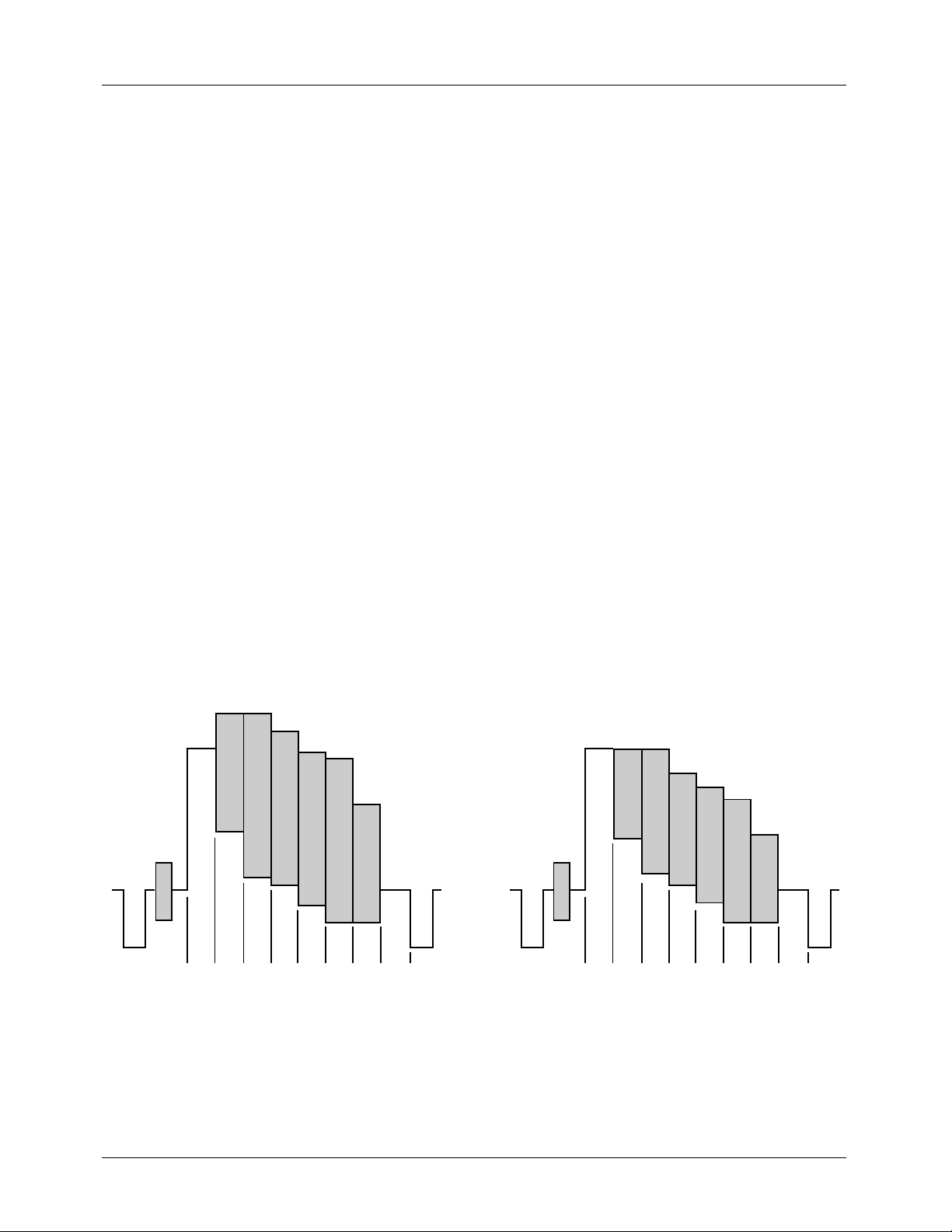
TMC22091/TMC22191 PRODUCT SPECIFICATION
SCH Phase Error Correction
SCH refers to the timing relationship between the 50% point
of the leading edge of horizontal sync and the positive or
negative zero-crossing of the color burst subcarrier reference. SCH error is usually expressed in degrees of subcarrier
phase. In PAL, SCH is defined for line 1 of field 1, but since
there is no color burst on line 1, SCH is usually measured at
line 7 of field 1. The need to specify SCH relative to a particular line in PAL is due to the 25 Hz offset of PAL subcarrier
frequency. Since NTSC has no such 25 Hz offset, SCH
applies to all lines.
The SCH relationship is only important in the TMC22x91
when two video sources are being combined or if the composite video output is externally combined with another
video source. In these cases, improper SCH phasing will
result in a noticeable horizontal jump of one image with
respect to another and/or a change in hue proportional to the
SCH error between the two sources.
SCH phasing can be adjusted by modifying BURPH and
SYSPH values by equal amounts. SCH is advanced/delayed
by one degree by increasing/decreasing the value of BURPH
and SYSPH by approximately B6
corrected with SYSPH and BURPH offsets of AAAh.
. An SCH error of 15° is
h
Video Test Signals
The TMC22x91 has two standard video test waveforms for
evaluating video signal integrity. They are selected and
controlled by the Format Control Register.
Setting the Format Control Register bits 0, 4, and 5 LOW
generates standard color bars at the COMPOSITE output
(Figure 11), the luminance component stair-step signal at the
LUMA output, and the chrominance component on the
CHROMA output. The six colors are 100% saturated PAL
and 75% saturated for NTSC.
The percentage color saturation is selectable via Misc.
Control Register 0E, bit 0.
The color bar test pattern comprises eight equal-width bars
during VA, the active video period. The Timing Register
value for CBL is found from:
CBL
If CBL is larger than this, the color bars are truncated at the
end of VA. If CBL is smaller than VA/8, the color bar
sequence will repeat, starting with another white bar. From
left to right color bars 1 to 8 should be white, yellow, cyan,
green, magenta, red, blue, and black.
The modulated ramp waveform is enabled by setting the For mat Control Register to 30h. It comprises constant-amplitude
and constant-phase subcarrier modulation superimposed on a
linear ramp which slews from black to white during the
active video portion of each horizontal line (Figure 12). This
waveform is useful in making differential gain and differential phase measurements. Differential gain is a measure of
the variation in saturation of a color as the luminance component is varied from black to white. Differential phase is a
measure of the variation in hue of a color as the luminance
component is varied from black to white.
VA 7+
------------------=
8
34
1 2 3 4 5 6 7 8 1 2 3 4 5 6 7 8
24387A
Figure 8. 100% Color Bars With 100% and 75% Chrominance Saturation
Page 35
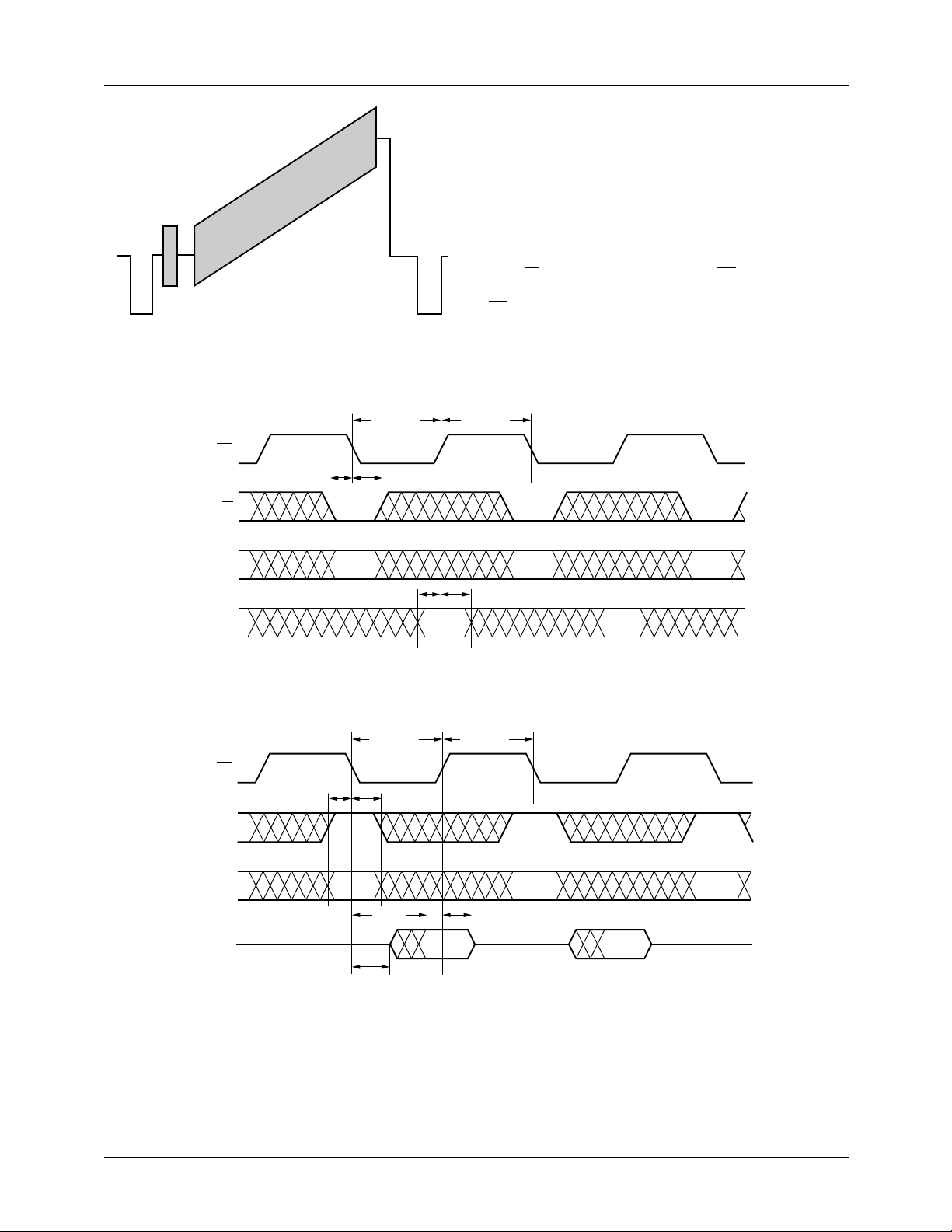
PRODUCT SPECIFICATION TMC22091/TMC22191
Microprocessor Interface
The microprocessor interface comprises 13-lines. Two
address bits provide four addresses for device programming
and CLUT/register management. Address bit 0 selects
between control registers and CLUT memory. Address bit 1
selects between reading/writing the register addresses and
reading/writing register or CLUT data.
When writing, the address is presented along with a LOW on
the R/W pin during the falling edge of CS. Eight bits of data
Figure 7. Modulated Ramp Waveform
24388A
are presented on D
.
CS
One additional falling edge of CS is needed to move input
data to the assigned working registers.
during the subsequent rising edge of
7-0
R/W
A1-A
D7-D
R/W
CS
CS
t
PWLCS
t
SA
0
0
t
HA
t
SD
t
PWHCS
t
HD
24323A
Figure 10. Microprocessor Port – Write Timing
t
SA
t
PWLCS
t
HA
t
PWHCS
A1-A
D7-D
0
t
DOM
0
t
DOZ
t
HOM
24324A
Figure 11. Microprocessor Port – Read Timing
35
Page 36
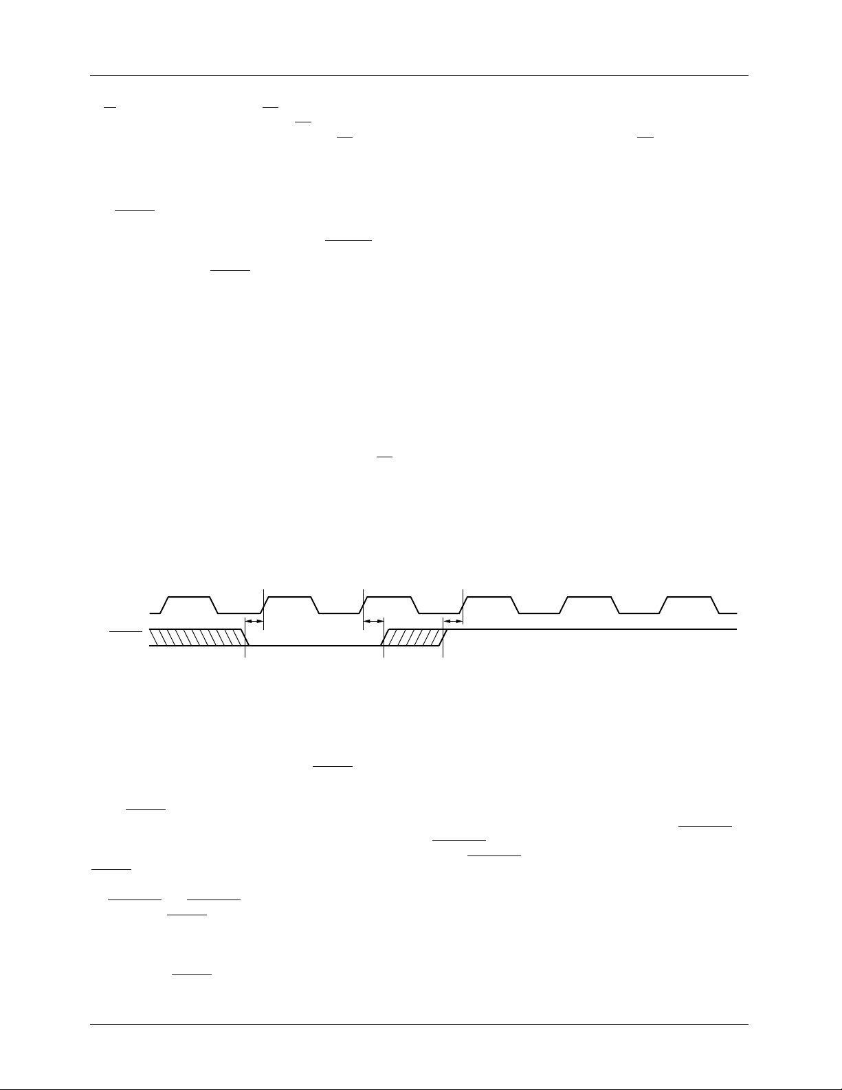
TMC22091/TMC22191 PRODUCT SPECIFICATION
In read mode, the address is accompanied by a HIGH on the
R/W pin during a falling edge of CS. The data output pins go
to a low-impedance state t
present on D
7-0 tDOM
after the falling edge of CS. Because
ns after CS falls. Valid data is
DOZ
this port operates asynchronously with the pixel timing,
there is an uncertainty in this data valid output delay of one
PXCK period. This uncertainty does not apply to t
The RESET pin restores the TMC22x91 to field 1 line 1 and
places the encoder in a power-down state (if HRESET is
LOW). Bit 4 of the Global Control Register (SRESET) is set
LOW. All other control words and CLUT contents are left
unchanged. Returning RESET
HIGH synchronizes the internal clock with PXCK and restores the device outputs to
active states.
Reading Pixel Data from the D
7-0
Port
The microprocessor port of the TMC22x91 may be used to
monitor digital video outputs. The eight MSBs of the upsampled and interpolated pixel data that go to the
COMPOSITE D/A converter can also be accessed via the
D
port. When the Test Control Register is loaded with 28h
7-0
and the Control Register pointer is loaded with 40h, the D
port will output the 8-bit composite pixels synchronous with
PXCK. To halt the pixel flow from D
, simply bring CS
7-0
HIGH.
Luminance pixel data may also be read from D
case, the eight MSBs of luminance at the input of the Sync
7-0
.
DOZ
. In this
7-0
and Blank Insert block are monitored. When the Control
Register pointer is loaded with 60
, the D
h
port will output
7-0
8-bit luminance pixels synchronous with respect to PXCK.
To halt the pixel flow from D
, bring CS HIGH.
7-0
Operational Timing
The TMC22x91 operates in three distinct modes:
1. Master mode. The encoder independently produces all
internal timing and provides digital sync to the host
controller.
2. Slave mode. The encoder accepts horizontal and v ertical
sync from the controller and synchronizes the video output accordingly.
3. Genlock mode. The encoder accepts horizontal and vertical sync from the companion TMC22071 Genlocking
Video Digitizer, synchronizes itself to the incoming
video, and provides appropriate H Sync and V Sync to
the host. It synchronizes Pixel Data input in two ways:
a. Internal PDC. The encoder internally generates the
Pixel Data Control (PDC) signal which calls for
data input from the external pixel source.
b. External PDC. The encoder receives a PDC signal
from the host and accepts Pixel Data based on that
input.
PXCK
RESET
t
SR
Figure 12. Reset Timing – PCK Synchronization
t
HR
Reset Timing
The TMC22x91 operates from a master clock (PXCK) at
twice the pixel rate. In Master mode, the PCK to PXCK timing relationship is set on the rising edge of RESET . In Figure
12, PCK is denoted by odd PXCK counts.
When RESET is taken LOW with sufficient setup time (tSR)
before a rising edge of PXCK, the internal state machines are
reset and the device is put into a mode as dictated by the Global Control Register bits 0 and 4. In Master mode, when the
RESET pin is taken HIGH, the internal clock timing is established. In Slave and Genlock mode, this timing is established
by VHSYNC
following this RESET rising edge is designated as PXCK 1.
Where it is significant, reference PXCK timing will be
shown with numbered rising edges. A designation of 2N
clocks refers to an even number of PXCK rising edges from
device reset. If RESET is not shown and clock numbering
and GHSYNC respectively. The first PXCK
1 2 3
t
SR
24330A
does not refer to 2N, timing is relative to signals shown in
the diagram only.
Pixel Data Input Timing
PXCK is internally divided by 2 to generate an internal pixel
clock, PCK which is not accessible from the pins of the
TMC22x91. To ensure the correct phase relationship
between PCK and pixel data, PCK is locked to VHSYNC or
GHSYNC (Slave or Genlock mode, respectively). In Master
mode, VHSYNC is produced on the rising edge of PCK
allowing external circuitry to synchronize the generation of
pixel data and LDV which also operates at the rate of PCK.
The rising edge of LDV clocks the 24-bit pixel data into
three 8-bit registers while PCK clocks that data through the
pixel data path within the TMC22x91. It is therefore necessary to meet the set-up and hold timing between pixel data
and LDV as well as LDV and PCK as shown in Figure 13.
36
Page 37
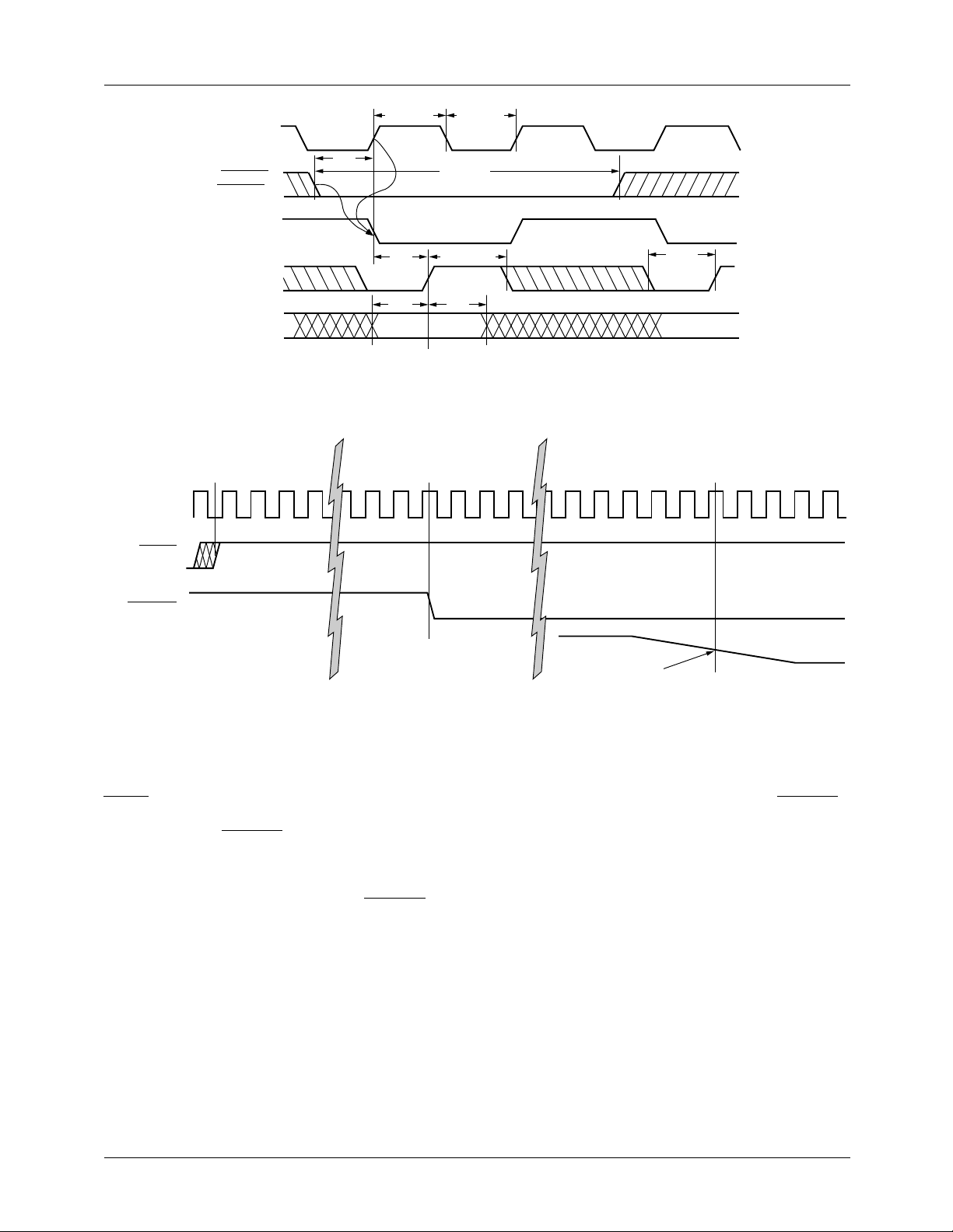
PRODUCT SPECIFICATION TMC22091/TMC22191
PXCK
RESET
PXCK
VHSYNC
(GHSYNC)
PCK
LDV
PD
KEY
t
PWHPX
2N+1 2N+2 2N+3
t
SP
t
XL
t
SP
t
PWLPX
t
PWLVH
t
PWHLDV
t
HP
t
PWLLDV
24340A
Figure 13. Slave Mode PD Port Interface Timing (Genlock Mode)
0
1 2 3 4 16 17 18 19 20 21 51 52 53 54 55 56 57 58 59 60
VHSYNC
COMPOSITE
OUTPUT
Figure 14. Master Mode Timing
Master Mode
In Master mode, initial timing is determined from the
RESET input, and subsequent cycles result from programmed values in the Timing Control Registers. The Horizontal Sync output, VHSYNC, goes LOW 18 PXCK clock
cycles after the device is reset. The 50% point of the falling
edge of sync LOW on line 4 of field 1 (NTSC) or line 1 of
field 1 (PAL) occurs at the COMPOSITE and LUMA outputs 56 clocks after reset, or 38 clocks after VHSYNC. See
Figure 14, Master Mode Timing.
50% Sync Amplitude
24353A
Slave Mode
In Slave mode, the 50% point of the falling edge of sync
occurs 46 PXCK clocks after the falling edge of VHSYNC,
which is an input signal to the TMC22x91. This must be provided by the host to begin every line. If it is early, the line
will be started early, maintaining the 52 clock delay to output. If it comes late, the front porch portion of the output
waveform will be extended as necessary. See Figure 15,
Slave Mode Timing.
37
Page 38
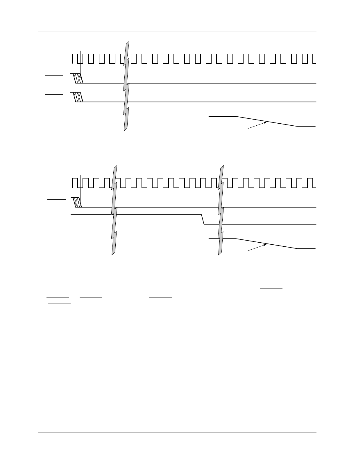
TMC22091/TMC22191 PRODUCT SPECIFICATION
2N+0
2N+1
2N+2
2N+3
2N+4
PXCK
2N+40
2N+41
2N+42
2N+43
2N+44
2N+45
2N+46
2N+47
2N+48
2N+49
2N+50
2N+51
2N+52
2N+53
2N+54
2N+55
2N+56
VHSYNC
VVSYNC
for field 1
COMPOSITE
OUTPUT
PXCK
GHSYNC
VHSYNC
COMPOSITE
OUTPUT
1
1
50% Sync Amplitude
24355A
Figure 15. Slave Mode Timing
2N+0
2N+1
2N+2
2N+3
2N+6
2N+7
2N+8
2N+9
2N+10
2N+11
2N+12
2N+13
2N+14
2N+47
50% Sync Amplitude
2N+48
2N+49
2N+50
2N+51
2N+52
2N+53
24356A
2N+54
Figure 16. Genlocked Mode Timing
Genlocked Mode
In Genlocked mode, the encoder receives sync signals over
the GHSYNC and GVSYNC inputs, and provides VHSYNC
and VVSYNC to the host. The 50% sync amplitude point
occurs 50 PXCK clocks after GHSYNC goes LOW, while
VHSYNC is produced at clock 13. If GHSYNC is late, the
front porch is lengthened, if is is early, front porch is
shortened. See Figure 16, Genlock Mode Timing.
Pixel Data Control
The Pixel Data Control (PDC) signal determines the active
picture area. It may be an input or an output, as determined
by the Interface Control Register bit 1.
38
The position (number of PCK cycles) of the rising edge of
PDC relative to the falling edge of VHSYNC
can be found
by summing SY, BU, BR, and CBP. See Figure 17.
External Pixel Data Control
When used as an input, PDC goes HIGH four PXCK cycles
before the first valid pixel of a line is presented to the PD
input port. If this signal is late (with respect to the horizontal
blanking interval programmed in the timing control registers), the Color Back Porch (CBP) will be extended. If it is
early, incoming pix el data will be ignored until the end of the
CBP.
Page 39
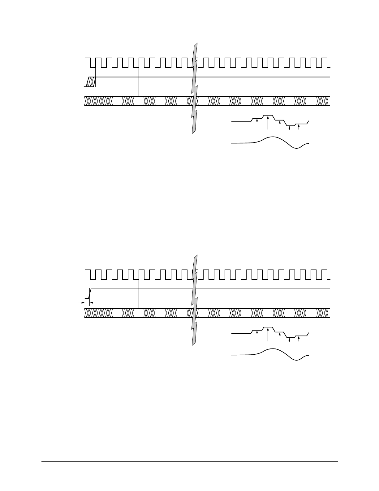
PRODUCT SPECIFICATION TMC22091/TMC22191
2N+0
2N+1
2N+2
2N+3
2N+4
2N+5
2N+6
2N+7
2N+8
2N+9
PXCK
PDC
2N+39
2N+40
2N+41
2N+42
2N+43
2N+44
2N+45
2N+46
2N+47
2N+48
2N+49
2N+50
PD
COMPOSITE
OUTPUT
POST-FILTER
OUTPUT
P
1
P
P
2
3
Figure 17. External Pixel Data Control
Internal Pixel Data Control
When programmed as an output, PDC goes HIGH four
PXCK periods prior to the end of CBP (as programmed in
the horizontal timing registers) which is also four PXCK
cycles prior to required input of the first pixel of a line.
2N+0
2N+1
2N+2
2N+3
2N+4
2N+5
2N+6
2N+7
2N+8
PXCK
P
P
4
19
P
20
P
21
P
22
P
PI1P2PI2P
1
P
23
3
Pixels produced by the encoder appear at the analog outputs
(COMPOSITE, LUMA, CHROMA) 40 clocks after they are
registered into the PD port. Note that the pixels enter at onehalf the PXCK rate. The encoded signal passes through
interpolation filters which generate intermediate output values, improving the output frequency response and greatly
simplifying the external reconstruction filter. The interpolated pixels are designated PI in the diagram.
2N+9
2N+39
2N+40
2N+41
2N+42
2N+43
2N+44
2N+45
2N+46
2N+47
P
24
2N+48
24358A
2N+49
2N+50
PDC
PD
COMPOSITE
OUTPUT
POST-FILTER
OUTPUT
t
DO
P
1
P
P
2
P
3
P
4
19
P
20
P
21
P
22
P
PI1P2PI2P
1
P
23
P
24
3
24357A
Figure 18. Internal Pixel Data Control
39
Page 40
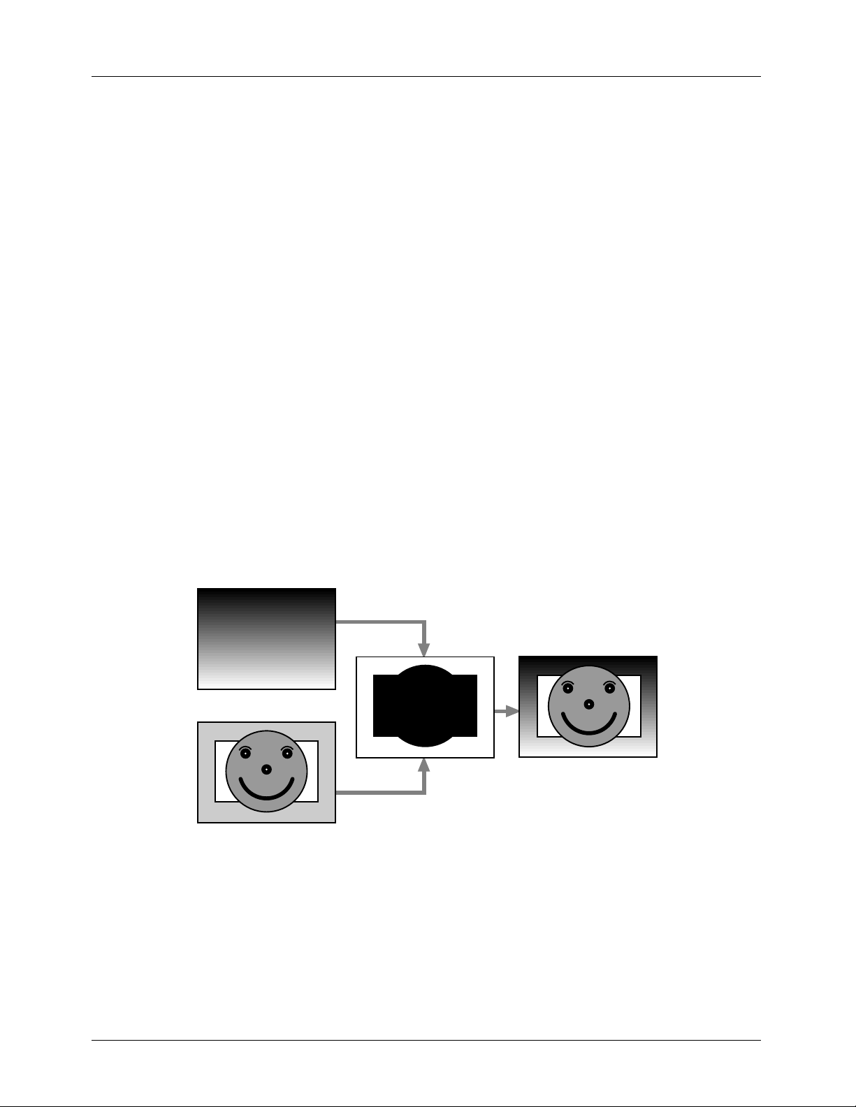
TMC22091/TMC22191 PRODUCT SPECIFICATION
Layering with the TMC22191
Layering is a video production process where various images
or patterns are superimposed (keyed) over each other to form
a layered composite of the input images. Four layers with the
following priority are provided by the TMC22191:
1. The DOWNSTREAM KEY layer keys over all other
layers.
2. The FOREGROUND layer keys over MIDGROUND
and BACKGROUND, but not over DOWNSTREAM
KEY.
3. The MIDGROUND layer keys over BACKGROUND,
but not over FOREGROUND or DOWNSTREAM
KEY.
4. The BACKGROUND layer never keys over any other
layer.
It is important not to confuse layers with sources. The
TMC22191 can be programmed to assign any of its input
sources (RGB, YC
the four layers.
The ability to combine various video sources into a 4-layer
composite image is a very powerful tool in the production of
live video. The TMC22191 performs layering operations
entirely in the digital domain, enabling precise digital
control.
, CVBS bus, Overlay bits) to any of
RCB
A 4-Layer Example
For this layering example, a BACKGROUND image is
generated. This image comprises shaded matte le vels v arying
from black at the top of the screen to white at the bottom.
This could just as well be a color image which will be seen
wherever no other image appears through the layering
process.
The MIDGROUND image comprises a happy face superimposed over a white rectangle. Only the happy face and the
white rectangle are of interest for this image and therefore,
the portion of the image outside that area will be replaced by
the BACKGROUND image when MIDGROUND is keyed
over BACKGROUND. A key signal is generated on a pixelby-pixel basis. It indicates which image is active. The key
signal for keying MIDGROUND over BACKGROUND is
shown to the right of the MIDGROUND image. This represents a single bit signal mapped over the image. When the
signal is black (logic LOW), the MIDGROUND image is
active, when it is white (logic HIGH), the BACKGROUND
is active.
The results of layering MIDGROUND over BACKGROUND images are shown in the 2-layer composite image
Figure 19.
BACKGROUND
MIDGROUND
Figure 19. 2-Layer Image Construction
A FOREGROUND image comprises a shaded matte rectangle with "HI KIDS !" alpha characters in its center. This is to
be superimposed over the previous 2-layer composite image.
The key signal needed for superimposing FOREGROUND
over other images is shown to the right of the FOREGROUND image. This represents a single bit signal mapped
over the image. When the signal is black (logic LOW), the
KEY 2-LAYER COMPOSITE
27036A
FOREGROUND image is active, when it is white (logic
HIGH), the composite image is active.
A new 3-layer composite image, FOREGROUND over
MIDGROUND over BACKGROUND, is shown in Figure
20.
40
Page 41
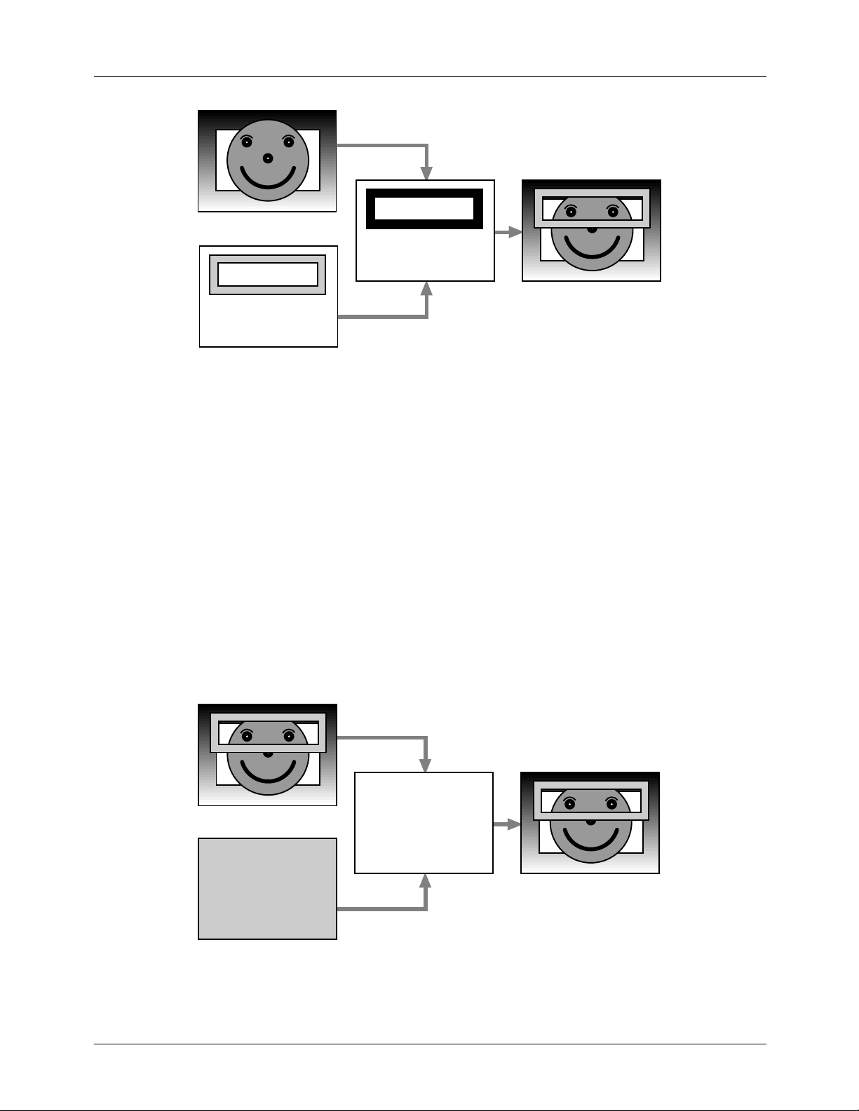
PRODUCT SPECIFICATION TMC22091/TMC22191
2-LAYER COMPOSITE
KEY 3-LAYER COMPOSITE
HI KIDS !
FOREGROUND
HI KIDS !
Figure 20. Adding a 3rd Layer
A DOWNSTREAM KEY image comprises the white alpha
characters "HAPPY FACE", and black alpha characters
"Time". This is to be superimposed over the previous 3-layer
composite image. The key signal needed for superimposing
DOWNSTREAM KEY image over the other composite
images is shown to the right. This represents a single bit signal mapped over the image. When the signal is black (logic
LOW), the DOWNSTREAM KEY image is active, when it
is white (logic HIGH), the previous composite image is
active.
The final 4-layer composite image, DOWNSTREAM KEY
over FOREGROUND over MIDGROUND over BACKGROUND, is shown in Figure 21.
HI KIDS !
27037A
In this illustration, all four source images are static (not moving). The images input to the TMC22191 can just as well be
"live" (from video camera or VCR sources) as long as:
• Data from those sources is in an input format that the
TMC22191 can accept, and
• The sources either synchronize the TMC22191
(Genlock mode) or are synchronized by the TMC22191
(Master or Slave mode).
Key signals may be generated external to the TMC22191
(Hardware Keying) and use the KEY input pin for control.
Key signals may also be generated within the TMC22191
(Data Keying) by the comparison of input color data with
color data stored in the TMC22191.
3-LAYER COMPOSITE
HI KIDS !
DOWNSTREAM KEY
HAPPY
FACE
TIME
KEY 4-LAYER COMPOSITE
HAPPY
FACE
TIME
Figure 21. Adding a 4th Layer
HI KIDS !
HAPPY
FACE
TIME
27038A
41
Page 42
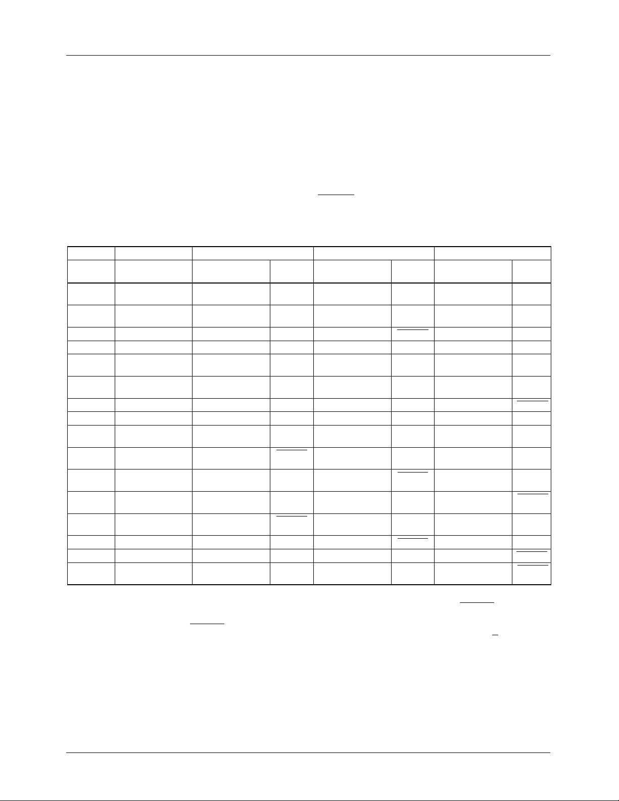
TMC22091/TMC22191 PRODUCT SPECIFICATION
2-Layer Keying with the TMC22091
The TMC22091 facilitates the keying of PD port input data
over the CVBS bus input data. Keying is controlled on a
pixel-by-pixel basis by either the KEY input pin or the internal Data Key. The first two layers in the previous 4-Layer
Example apply to the TMC22091. The result of keying is an
effect where a MIDGROUND source image (i.e. Happ y Face
from PD data) is superimposed over a BACKGROUND
source image (i.e. variable matte color from CVBS data).
Assigning Video Sources to Layers with the
TMC22191
Digital video inputs to the TMC22191 (PD, CVBS, Overlay)
are assigned to the four layers by choosing one of the 16
modes of the Layering Control Register. OVERLAY is
always keyed (switched on a pixel-by-pix el basis from activ e
to transparent) by the OL
programmed to the BACKGROUND layer. The CVBS digital video bus can be assigned to any of the four layers and is
inputs. OVERLAY can not be
4-0
keyed by the KEY input signal or internal Data Key. In
modes 0 thru 7, the CLUTs are not bypassed and the
BYPASS
input is ignored.
Table 14. Layer Assignments, Image Sources, and Keying Controls (TMC22191)
LCR 04 Background Midground Foreground Downstream Key
LAYMODE Image Source Image Source
0 PD(YCBCR, RGB, CI) CVBS KEY or
1 PD(YCBCR, RGB, CI) CVBS KEY or
2 PD(YCBCR, RGB, CI) CVBS KEY PD(YCBCR, RGB, CI) Data Key OVERLAY OL
3 PD(YCBCR, RGB, CI) CVBS KEY PD(YCBCR, RGB, CI) Data Key OVERLAY OL
4 CVBS OVERLAY OL
5 CVBS PD(YCBCR, RGB, CI) KEY or
6 PD(YCBCR, RGB, CI) CVBS KEY OVERLAY OL
7 PD(YCBCR, RGB, CI) CVBS KEY OVERLAY OL
8 PD(YCBCR, CI) CVBS KEY or
9 PD(RGB) PD(YCBCR, CI) BYPASS CVBS KEY or
A PD(RGB) CVBS KEY or
B PD(RGB) CVBS KEY or
C PD(RGB) PD(YCBCR, CI) BYPASS OVERLAY OL
D CVBS PD(RGB) KEY PD(YCBCR, CI) BYPASS OVERLAY OL
E CVBS OVERLAY OL
F PD(RGB) OVERLAY OL
Keying
Control Image Source:
Data Key
Data Key
4-0
Data Key
Data Key
Data Key
Data Key
4-0
4-0
PD(YCBCR, RGB, CI) KEY or
— — — —
OVERLAY OL
OVERLAY OL
PD(YCBCR, CI) BYPASS OVERLAY OL
OVERLAY OL
PD(RGB) KEY PD(YCBCR, CI) BYPASS
CVBS KEY or
Keying
Control Image Source:
4-0
Data Key
4-0
PD(YCBCR, RGB, CI) Data Key
4-0
PD(YCBCR, RGB, CI) Data Key
4-0
— — —
Data Key
4-0
4-0
Data Key
OVERLAY OL
PD(YCBCR, CI) BYPASS
PD(YCBCR, CI) BYPASS
Keying
Control
— —
4-0
4-0
— —
— —
4-0
4-0
CVBS KEY or
Data Key
4-0
Notes:
1. For LAYMODE = 0 to 7, Pixel Data always passes through the CLUTs. FORMAT, INMODE, and the BYPASS
input format for PD
2. For LAYMODE = 8 to F and BYPASS
according to Table 6.
23-0
= HIGH, Data Key is disabled.
3. Asserting the signal listed under "Keying Control:" enables the corresponding "Signal Source:". Signals with "
by a logic LOW.
42
pin selects the
" are asserted
Page 43
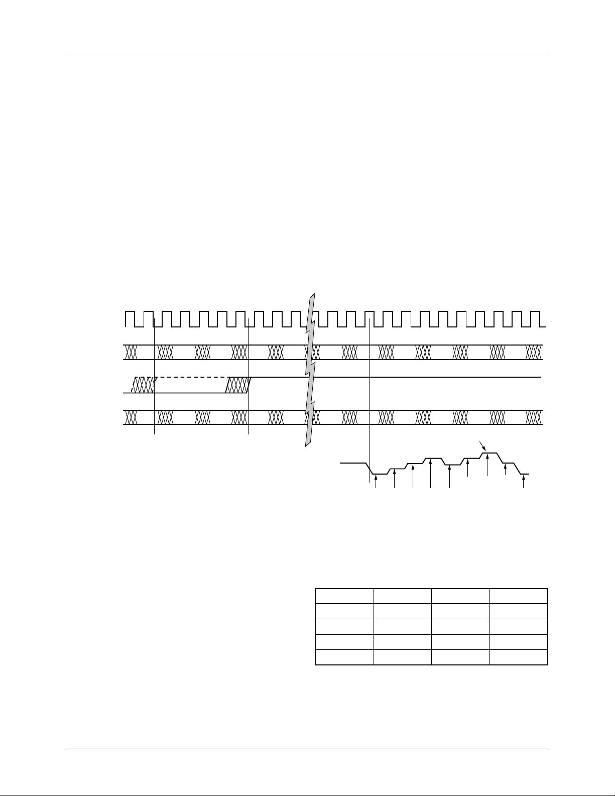
PRODUCT SPECIFICATION TMC22091/TMC22191
Hardware Keying
The KEY input switches the COMPOSITE D/A converter
input from the luminance and chrominance combiner output
to the CVBS data bus on a pixel-by-pixel basis. This is a
"soft" switch, executed over four PXCK periods to minimize
out-of-band spurious signals. The video signal from the
CVBS bus can only present on the COMPOSITE output. The
CHROMA and LUMA outputs continue to present encoded
PD port data when CVBS is active.
Hardware keying is enabled by the Key Control Register bit
6. Normally, k eying is only ef fecti ve during the Active V ideo
portion of the waveform as determined by the VA registers
15 and 18. The Horizontal Blanking interval is generated by
the encoder state machine even if the KEY signal is held
HIGH through Horizontal Blanking. However, it is possible
to allow digital Horizontal Blanking to be passed through
from the CVBS bus to the COMPOSITE output by setting
0 1 2 3 4 5 6 7 8 9 38 39 40 41 42 43 44 45 46 47 48 49
PXCK
CVBS
V
N+2
V
N+3
V
N+4
V
N+5
V
N+6
Key Control Register bit 5 HIGH. In this mode, KEY is
always active, and may be exercised at will.
The KEY input is registered into the encoder just like Pixel
Data is clocked into the PD port. It may be considered a 25th
Pixel Data bit. It is internally pipelined, so the midpoint of
the key transition occurs at the output of the pixel that was
input at the same time as the KEY signal.
Data Keying
Data Keying internally generates a Key signal that acts
exactly as the external KEY signal. There are three Key
Value Registers 05, 06, and 07 that are matched against the
input data to the three tables in the CLUT. These tables are
designated D, E, and F. They contain different information
depending on the input mode selected as shown in Table 16.
V
N+25
V
N+26
V
N+27
V
N+28VN+29VN+30
KEY
PD
COMPOSITE
OUTPUT
*
P
KEY is advanced five PXCK cycles when
*
Control Register OE bit 4 is HIGH (TMC22191).
P
N
N+1
P
N+2
P
N+3
Figure 22. Hardware Keying
P
N+4
The key registers may be individually enabled using bits
3,2,1 of the Key Control Register. Bit 4 of the same register
enables/disables Data Keying in its entirety . Data K eying and
Hardware Keying are logically ORed: when both are
enabled, either one will result in a key switch to the CVBS
channel.
The key comparison is based on the input data to the tables
in the CLUT. When operating in color-index mode, all three
tables receive the same input value, so any one of the three
registers is sufficient to identify a key value. The outputs of
all enabled key registers are ANDed to produce the KEY signal. If more than one key register are enabled and their key
values are not identical, no key will be generated.
P
N+23
P
N+24
P
N+25
PNPINP
P
N+26PN+27PN+28
KEY MIDPOINT
N+1
VI
N+1
N+1
PI
N+2
P
N+2
PI
N+2
VI
N+3
P
Table 16. Table D, E, F Contents
Mode Table D Table E Table F
GBR Green Blue Red
RGB Red Green Blue
YCBC
R
CI CI CI CI
Y C
B
N+2
VI
N+3
PI
C
N+3
V
24359A
R
43
Page 44
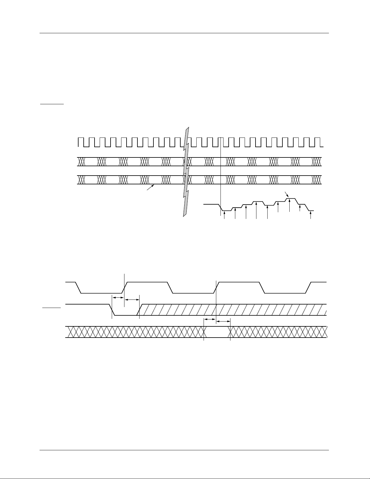
TMC22091/TMC22191 PRODUCT SPECIFICATION
Genlock Interface
The TMC22x91 can process digital composite video
connected to its CVBS port. It has been designed to couple
tightly with the companion TMC22071 Genlocking Video
Digitizer, but it will work with other sources as well.
The digital composite video has to be in standard 8-bit
binary format at a PXCK/2 rate. Synchronization with the
internal PXCK/2 is established by the phasing of the
GHSYNC input, as shown in Figures 24 and 25.
0 1 2 3 4 5 6 7 8 9 38 39 40 41 42 43 44 45 46 47 48 49
PXCK
Subcarrier frequency and phase data are transmitted to the
encoder over the CVBS bus as 4-bit nibbles on CVBS
3-0
during the horizontal sync period. Field identification is also
required for the TMC22x91 internal sync generator. The
14th nibble of the sequence contains no relevant data.
COMPOSITE
OUTPUT
PXCK
GHSYNC
CVBS
7-0
CVBS
PD
V
N+2
P
V
N+3
P
N
N+1
V
N+4
P
N+2
FIRST KEY WORD
V
P
N+5
N+3
V
P
N+6
N+4
V
P
N+25
N+23
V
P
N+26
N+24
V
N+27
P
N+25
PNPINP
V
N+28VN+29VN+30
P
N+26PN+27PN+28
KEY MIDPOINT
N+5
VI
N+1
N+1
PI
N+2
P
N+2
PI
N+6
VI
N+3
P
N+6
VI
N+3
PI
N+7
V
24360A
Figure 23. Data Keying
t
SGI
2N+1
t
HGI
t
SGI
2N+2 2N+3
t
HGI
24341A
Figure 24. Genlock Interface Timing
44
Page 45
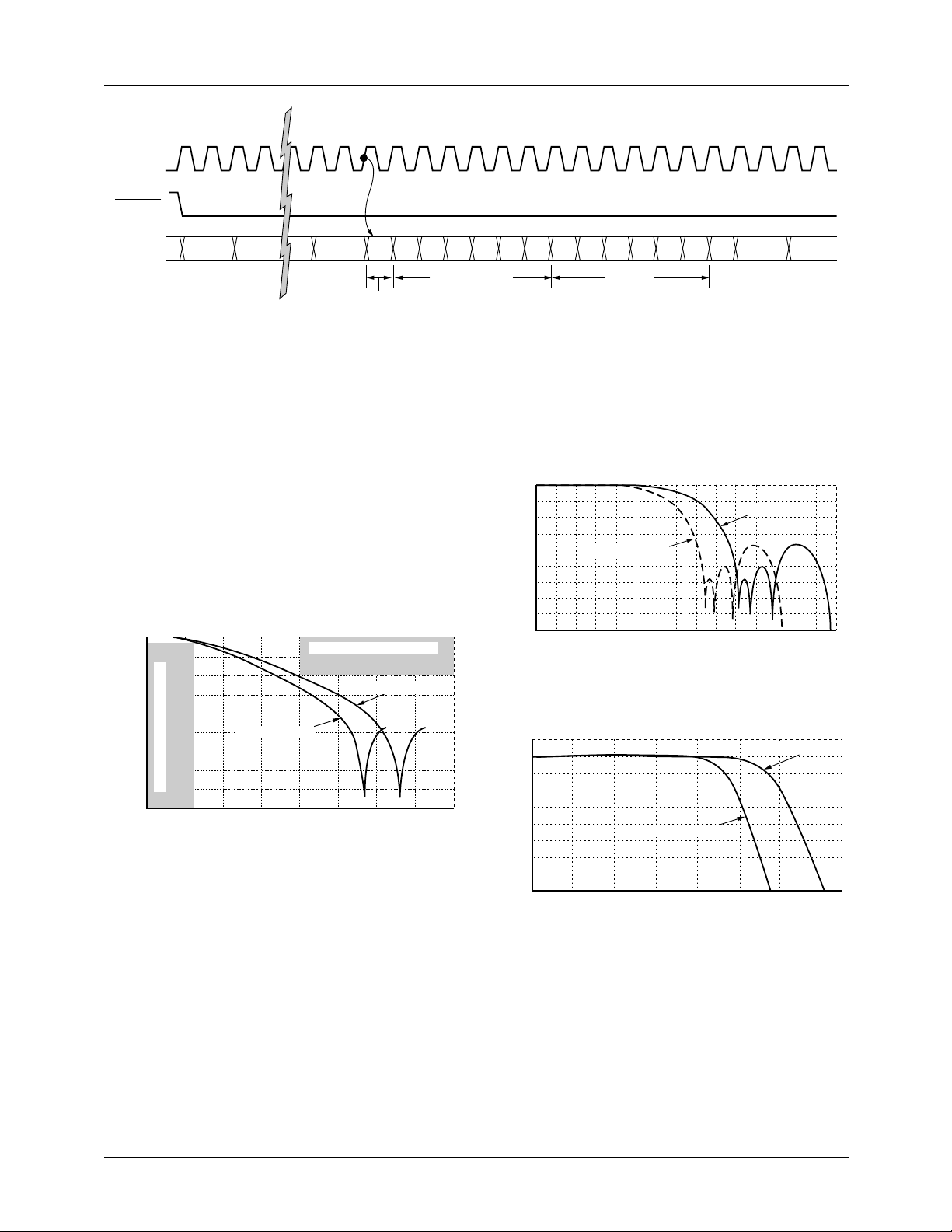
PRODUCT SPECIFICATION TMC22091/TMC22191
PXCK
0 1 2 3 57 58 59 60 61 62 63 64 65 66 67 68 69 70 71 72 73 74 75 76
GHSYNC
4
CVBS
7-0
PIXEL PIXEL PIXEL
FIELD IDENTIFICATION
f
23:20f19:16f15:12f11:8f7:4f3:0φ23:20φ19:16φ15:12φ11:8φ7:4φ3:0
FREQUENCY PHASE
Figure 25. Frequency/Phase Data Transfer
Filtering
The TMC22x91 incorporates internal digital filters to establish appropriate bandwidths and simplify external analog filter designs.
Color-Difference Low-Pass Filters
The color-difference low-pass filters in the TMC22x91
establish chrominance bandwidths which meet the specifications outlined in CCIR Report 624-3, Table II, Item 2.6, for
system I over a range of pixel rates from 12.27 Mpps to
14.75 Mpps. Equal bandwidth is established for both color-
difference channels.
0
-10
-20
-30
-40
-50
-60
Attenuation (dB)
-70
CCIR Rep 624 Specification
-80
-90
1 2 3 4 5 6 7 8
0
f = 12.27 Mpps
Frequency (MHz)
Figure 26. Color-Difference Low-Pass Filter Response
CCIR Rep 624 Specification
f = 14.27 Mpps
24363A
PIXEL PIXELFID
24383A
Since these are fixed-coefficient digital filters, their filter
characteristics depend upon clock rate. Figures 26 and 27
show the frequency response for two pixel rates, 12.27 MHz
and 14.75 MHz.
0
-10
-20
-30
-40
-50
-60
Attenuation (dB)
-70
-80
-90
0
f = 12.27 Mpps
3 6 9 12 15
Frequency (MHz)
Figure 27. Chroma Modulator and Luminance
Interpolation Filter Full Spectrum Response
0
-1
-2
Attenuation (dB)
-3
f = 12.27 Mpps
f = 14.75 Mpps
24394A
f = 14.75 Mpps
Interpolation Filters
The Chroma Modulator output and the luminance data path
are digitally filtered with sharp-cutoff low-pass interpolation
filters. These filters ensure that aliased subcarrier, chrominance, and luminance frequencies are sufficiently suppressed
in the frequency band above base-band video and below the
pixel frequency (fS/4 to 3fS/4, where fS is the PXCK
frequency).
-4
1 2 3 4 5 6
0
Frequency (MHz)
7
24365A
Figure 28. Chroma Modulator and Luminance
Interpolation Filter Passband Detail
All digital-to-analog reconstruction systems exhibit a high
frequency roll-off as a result of the zero-order hold characteristic of D/A converters. This response is commonly
referred to as a sin(x)/x response. It is a function of the sampling rate of the output D/A.
45
Page 46
TMC22091/TMC22191 PRODUCT SPECIFICATION
The digital interpolation filters in TMC22x91 convert the
JTAG Test Interface
data stream to a sample rate of twice the pixel rate. As sho wn
in Figures 27 and 28, the filters decrease the sin(x)/x rolloff
and the output spectrum between fS/4 and 3fS/4 contains
very little energy. Since there is so little signal energy in this
frequency band, the demands placed on the output reconstruction filter are greatly reduced. The output filter needs to
be flat to fS/4 and have good rejection at 3fS/4. The relaxed
requirements greatly simplify the design of a filter with good
phase response and low group delay distortion. A small
amount of peaking may be used to compensate residual
sin(x)/x rolloff.
The JTAG test port accesses registers at every digital I/O pin
except the JTAG test port pins. Table 16 shows the sequence
of the test registers. The register number (Reg) indicates the
order in which the register data is loaded and read (Reg 1 is
loaded and read first, therefore it is at the end of the serial
path). The scan path is 59 registers long. The six TEST pins
of the TMC22091 function as JTAG registers.
The JTAG port is a 4-line interface, following IEEE Std.
1149.1-1990 specifications. The Test Data Input (TDI) and
Test Mode Select (TMS) inputs are referred to the rising
edge of the Test ClocK (TCK) input. The Test Data Output
(TDO) is referred to the falling edge of TCK.
Table 16. JTAG Interface Connections
Reg Pin Signal Reg Pin Signal Reg Pin Signal
1 28 BYPASS (TEST) 21 62 PD
2 29 OL4 (TEST) 22 63 PD
3 44 CVBS
4 45 CVBS
5 46 CVBS
6 47 CVBS
7 48 OL3 (TEST) 27 70 PD
7
6
5
4
23 66 PD
24 67 PD
25 68 PD
26 69 PD
8 49 OL2 (TEST) 28 71 PD
9 50 OL1 (TEST) 29 72 PD
10 51 OL0 (TEST) 30 73 PD
11 52 PD
12 53 PD
13 54 PD
14 55 PD
15 56 PD
16 57 PD
17 58 PD
18 59 PD
19 60 PD
20 61 PD
23
22
21
20
19
18
17
16
15
14
31 74 PD
32 75 PD
33 76 PD
34 77 PD
35 78 LDV 55 17 D
36 79 PXCK 56 18 D
37 82 GVSYNC 57 19 D
38 83 GHSYNC 58 20 D
39 84 CVBS
40 1 CVBS
13
12
11
10
9
8
7
6
5
4
3
2
1
0
3
2
41 2 CVBS
42 3 CVBS
43 4 KEY
44 5 RESET
45 6 CS
46 7 R/W
47 8 A
48 9 A
49 11 PDC
50 12 VHSYNC
51 13 VVSYNC
52 14 D
53 15 D
54 16 D
59 21 D
1
0
1
0
7
6
5
4
3
2
1
0
46
Page 47
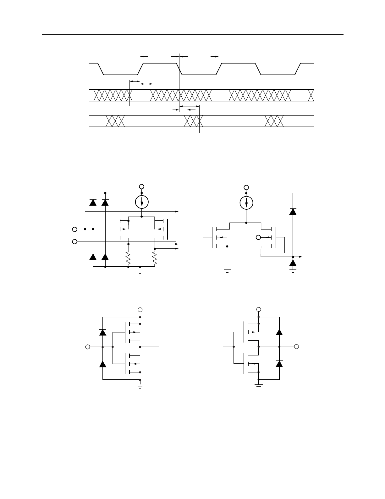
PRODUCT SPECIFICATION TMC22091/TMC22191
TCK
TDI
TMS
TDO
Equivalent Circuits
n Substrate
R
REF
V
REF
t
STP
t
PWLTCK
t
HTP
t
HOTP
t
PWHTCK
t
DOTP
Figure 29. JTAG Test Port Timing
V
DD
27012A
V
DD
n p
V
DD
24333A
COMPOSITE
LUMA
CHROMA
27013A
Figure 30. Equivalent Analog Input Circuit Figure 31. Equivalent Analog Output Circuit
V
DD
p
Output
n
27011A
Input
n Substrate
p
n
V
DD
27014A
Figure 32. Equivalent Digital Input Circuit Figure 33. Equivalent Digital Output Circuit
47
Page 48
TMC22091/TMC22191 PRODUCT SPECIFICATION
t
DOM
CS
t
HOM
0.5V
D
7-0
Figure 34. Transition Levels for Three-State Measurements
Hi-Z
0.5V
Absolute Maximum Ratings (beyond which the device may be damaged)
t
DOZ
2.0V
0.8V
27029A
1
Parameter Min. Max. Unit
Power Supply Voltage -0.5 7.0 V
Digital Inputs
3,4
2
-0.5 VDD+0.5 V
-20.0 20.0 mA
Applied Voltage
Forced Current
Digital Outputs
3,4
2
-0.5 VDD+0.5 V
-20.0 20.0 mA
Applied Voltage
Forced Current
Short Circuit Duration (Single output in HIGH state to GND) 1 second
Analog Output Short Circuit Duration (Single output to GND) Infinite
Temperature
Operating, ambient -20 110 °C
Operating, junction, plastic package 140 °C
Lead, soldering (10 seconds) 300 °C
Vapor phase soldering (1 minute) 220 °C
Storage -65 150 °C
Notes:
1. Absolute maximum ratings are limiting values applied individually while all other parameters are within specified operating
conditions. Functional operation under any of these conditions is NOT implied.
2. Applied voltage must be current limited to specified range, and measured with respect to GND.
3. Forcing voltage must be limited to specified range.
4. Current is specified as conventional current, flowing into the device.
48
Page 49
PRODUCT SPECIFICATION TMC22091/TMC22191
Operating Conditions
Parameter Min. Nom. Max. Units
V
DD
V
IH
V
IL
I
OH
I
OL
V
REF
I
REF
R
REF
R
OUT
T
A
Pixel Interface
f
PXL
f
PXCK
t
PWHPX
t
PWLPX
For PD, VVSYNC, VHSYNC, PDC, KEY
t
SP
t
HP
t
HP
t
XL
t
PWHLDV
t
PWLLDV
t
PWLVH
t
PWHVV
Genlock Interface
t
SGI
t
HGI
Microprocessor Interface
t
PWLCS
t
PWHCS
t
SA
t
HA
t
SD
t
HD
Power Supply Voltage 4.75 5.0 5.25 V
Input Voltage, Logic HIGH
TTL Compatible Inputs, all but TCK 2.0 V
TTL Compatible Input TCK 2.5 V
CMOS Compatible Inputs (2/3)V
DD
V
DD
DD
DD
V
V
V
Input Voltage, Logic LOW
TTL Compatible Inputs GND 0.8 V
CMOS Compatible Inputs GND (1/3)V
DD
V
Output Current, Logic HIGH -2.0 mA
Output Current, Logic LOW 4.0 mA
External Reference Voltage 1.235 V
D/A Converter Reference Current, V
(I
= V
REF
Reference Resistor, V
REF
/ R
, flowing out of the R
REF
= Nom. 281 392 588 Ω
REF
= Nom. 2.1 3.15 4.4 mA
REF
pin)
REF
Total Output Load Resistance 37.5 Ω
Ambient Temperature, Still Air 0 70 °C
Pixel Rate 12.27 15 Mpps
Master Clock Rate, 2x pixel rate 24.54 30 MHz
PXCK Pulse Width, HIGH 10 ns
PXCK Pulse Width, LOW 10 ns
Setup Time 12 ns
Hold Time, PD and KEY 0 ns
Hold Time, PDC, VHSYNC, VVSYNC 5 ns
Delay Time, LDV 10 ns
LDV Pulse Width, HIGH 15 ns
LDV Pulse Width, LOW 10 ns
VHSYNC Pulse Width, LOW 6 15 PXCK
periods
VVSYNC Pulse Width, LOW 0.5 3 H
Setup Time, GHSYNC, GVSYNC, CVBS 10 ns
Hold Time, GHSYNC, GVSYNC, CVBS 0 ns
CS Pulse Width, LOW 55 ns
CS Pulse Width, HIGH 30 ns
Address Setup Time 10 ns
Address Hold Time 0 ns
Data Setup Time (write) 15 ns
Data Hold Time (write) 0 ns
49
Page 50
TMC22091/TMC22191 PRODUCT SPECIFICATION
Operating Conditions (continued)
Parameter Min. Nom. Max. Units
t
t
SR
HR
Reset Setup Time 24 ns
Reset Hold Time 2 ns
JTAG Interface
f
TCK
t
PWLTCK
t
PWHTCK
t
STP
t
HTP
Note:
1. Timing reference points are at the 50% level.
Test Clock (TCK) Rate 20 MHz
TCK Pulse Width, LOW 10 ns
TCK Pulse Width, HIGH 25 ns
Test Port Setup Time, TDI, TMS 10 ns
Test Port Hold Time, TDI, TMS 3 ns
Electrical Characteristics
Parameter Conditions Min. Typ. Max. Units
1
1
REF
VDD = Max, f
VDD = Max, f
V
= Nom 100 µA
REF
= 0 mA, f = 1 MHz 15 25 pF
OUT
= 30MHz 250 300 mA
PXCK
= 30MHz 60 mA
PXCK
DD
DD
10 µA
10 µA
I
DD
I
DDQ
V
RO
I
BR
I
IH
I
IL
V
OH
V
OL
I
OZH
I
OZL
C
I
C
O
V
OC
R
OUT
C
OUT
Note:
1. Typical I
Power Supply Current
Power Supply Current
(D/A disabled)
Voltage Reference Output 0.988 1.235 1.482 V
Input Bias Current, V
Input Current, Logic HIGH VDD = Max, VIN = V
Input Current, Logic LOW VDD = Max, VIN = 0V -10 µA
Output Voltage, Logic HIGH IOH = Max 2.4 V
Output Voltage, Logic LOW IOL = Max 0.4 V
Hi-Z Leakage current, HIGH VDD = Max, VIN = V
Hi-Z Leakage current, LOW VDD = Max, VIN = GND -10 µA
Digital Input Capacitance TA = 25°C, f = 1MHz 4 10 pF
Digital Output Capacitance TA = 25°C, f = 1MHz 10 pF
Video Output Compliance Voltage -0.3 2.0 V
Video Output Resistance 15 kΩ
Video Output Capacitance I
with VDD = +5.0 Volts and TA = 25°C, Maximum IDD with VDD = +5.25 Volts and TA = 0°C.
DD
50
Page 51
PRODUCT SPECIFICATION TMC22091/TMC22191
Switching Characteristics
Parameter Conditions Min. Typ. Max. Units
PIPES Pipeline Delay
t
DOZ
t
DOM
t
HOM
t
DOTP
t
HOTP
Output Delay, CS to low-Z 6 23 ns
Output Delay, CS to Data Valid
Output Hold Time, CS to hi-Z 10 ns
Output Delay, TCK to TDO Valid 30 ns
Output Hold Time, TCK to TDO
Valid
t
DOS
t
R
t
F
t
DOV
Notes:
1. Timing reference points are at the 50% level.
2. Analog C
3. Pipeline delay, with respect to PXCK, is a function of the phase relationship between the internally generated PCK (PXCK/2)
and PXCK, as established by the hardware reset.
4. t
DOM
Output Delay PXCK to VHSYNC,
D/A Output Current Risetime 10% to 90% of full-scale 2 ns
D/A Output Current Falltime 90% to 10% of full-scale 2 ns
Analog Output Delay 20 ns
< 10 pF, D
LOAD
= 1 PXCK + 54 ns = 100 ns worst-case at PXCK = 24.54 MHz.
3
load < 40 pF.
7-0
PD to Analog Out 44 44 44 PXCK
4
100 ns
5 ns
25 ns
VVSYNC, PDC
periods
System Performance Characteristics
Parameter Conditions Min. Typ. Max. Units
RES D/A Converter Resolution 10 10 10 Bits
ELI Integral Linearity Error 0.25 %
ELD Differential Linearity Error 0.20 %
EG Gain Error ±10 % FS
dp Differential Phase PXCK = 24.54 MHz,
40 IRE Ramp
dg Differential Gain PXCK = 24.54 MHz,
40 IRE Ramp
3
3
SKEW CHROMA to LUMA Output Skew 0 2 ns
PSRR Power Supply Rejection Ratio CCOMP = 0.1 µF, f = 1kHz 0.5 %/
Notes:
1. TTL input levels are 0.0 and 3.0 Volts, 10%-90% rise and fall times <3 ns.
2. Analog C
3. NTSC
LOAD
< 10 pF, D
load < 40 pF.
7-0
0.5 degree
0.9 %
%VDD
51
Page 52
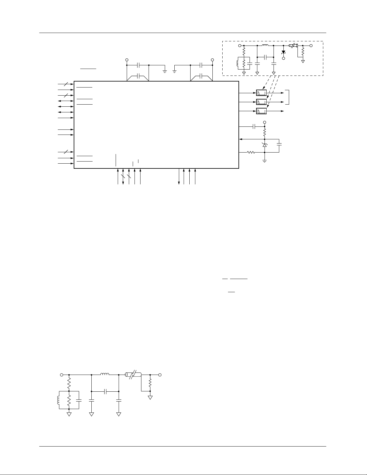
TMC22091/TMC22191 PRODUCT SPECIFICATION
FRAME
BUFFER
INTERFACE
CLOCKSGENLOCK
INTERFACE
5
24
8
BYPASS and OL
on TMC22191 only.
OL
4-0
BYPASS
PD
23-0
VHSYNC
VVSYNC
PDC
KEY
LDV
PXCK
CVBS
7-0
GHSYNC
GVSYNC
+5V
47 µF
4-0
0.1 µF
DO
D
V
TMC22x91
DIGITAL VIDEO
ENCODER
7-0
1-0
RESET
D
A
CS
R/W
8 2
MICROPROCESSOR
INTERFACE
Figure 35. Recommended Interface Circuit
GND
A
GND
TDO
TCK
TMS
JTAG TEST
INTERFACE
47 µF
0.1 µF
TDI
+5V
V
DDA
CHROMA
COMPOSITE
Video
from
Encoder
1.0µH
LUMA
COMP
V
REF
R
REF
1.8µH
75Ω 75Ω
27pF
100
75
pF
Ω
LM185-1.2
330pF 330pF
LPF
LPF
LPF
V
DD
0.1 µF
3.3KΩ
392Ω 0.1µF
IN5818
+5V
S-VIDEO OUTPUT
COMPOSITE VIDEO
27007A
OUTPUT
ANALOG
INTERFACE
Video
Output
Applications Discussion
The TMC22x91 is a complex mixed-signal VLSI circuit. It
converts digital video signals at clock rates of up to 30 MHz
to analog video outputs. A recommended circuit connection
is shown in Figure 35.
References
The circuit shown in Figure 35 uses a stable external 1.235V
voltage reference. To use the internal voltage reference, simply delete the 3.3kΩ resistor and the LM185-12. A simple
voltage divider from the power supply should NOT be used,
as any variations in power supply voltage would appear
directly on the video outputs.
Filtering
An simple low-pass output reconstruction filter is shown in
Figure 36. This filter is located in the video signal path after
the COMPOSITE, LUMA, and CHROMA outputs. The
value of R
Video
from
Encoder
1.0µH
may be varied to make up for the filter loss.
REF
75Ω 75Ω
75
Ω
100
pF
1.8µH
27pF
330pF 330pF
27025A
Video
Output
Interface to the TMC22071 Genlocking Video
Digitizer
The TMC22x91 Digital Video Encoder has been designed to
directly interface to the TMC22071 Genlocking Video Digitizer. An interface circuit is shown in Figure 37. The microprocessor interface for TMC22x91 and TMC22071 are
similar. The R/W, RESET, D0 and A0 signals from the host
microprocessor are shared by the TMC22x91 and
TMC22071. The CS signals are separately driven from the
microprocessor bus.
Grounding Strategy
The TMC22x91 has distinctly separate analog and digital
circuits. To minimize digital crosstalk into the analog signals, the power supplies and grounds are provided ov er separate pins. In general, the best results are obtained by
connecting all grounds to a ground plane. Power supply pins
should be individually decoupled at the pin.
Figure 36. Recommended Output Reconstruction Filter
52
Page 53
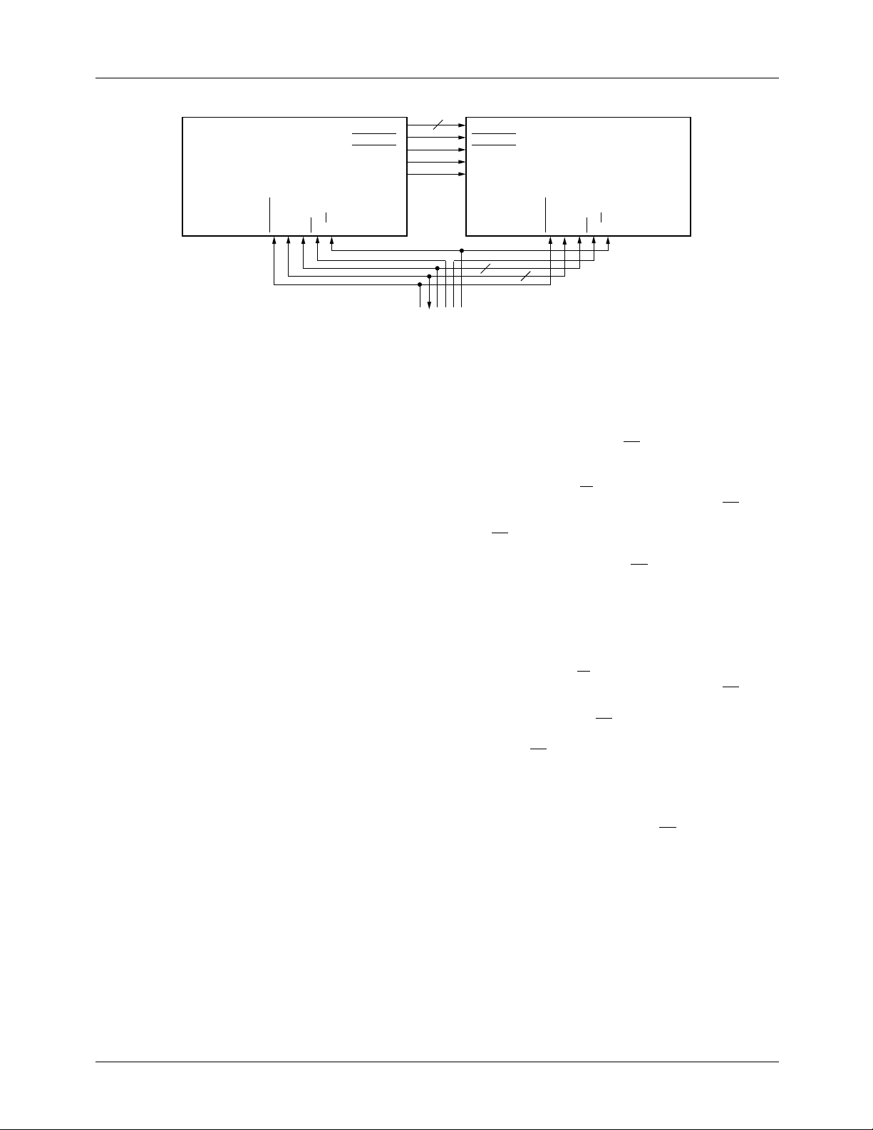
PRODUCT SPECIFICATION TMC22091/TMC22191
CVBS
7-0
GHSYNC
GVSYNC
R/W
PXCK
LDV
MICROPROCESSOR
INTERFACE
TMC22071
GENLOCKING VIDEO DIGITIZER
RESET
D0A0CS
Figure 37. TMC22x91-to-TMC22071 Interface Circuit
Printed Circuit Board Layout
Designing with high-performance mixed-signal circuits
demands printed circuits with ground planes. Overall system
performance is strongly influenced by the board layout.
Capacitive coupling from digital to analog circuits may
result in poor picture quality. Consider the following suggestions when doing the layout:
• Keep analog traces (COMP, V
far from all digital signals as possible.
• The power plane for the TMC22x91 should be separate
from that which supplies other digital circuitry. A single
power plane should be used for all of the V
power supply for the TMC22x91 is the same for the
system’s digital circuitry, power to the TMC22x91 should
be filtered with ferrite beads and 0.1µF capacitors to
reduce noise.
• The ground plane should be solid, not cross-hatched.
Connections to the ground plane should be very short.
• Decoupling capacitors should be applied liberally to VDD
pins. For best results, use 0.1µF capacitor in
parallel with 47µF capacitors. Lead lengths should be
minimized. Ceramic chip capacitors are the best choice.
• The PXCK should be handled carefully. Jitter and noise
on this clock or its ground reference will translate to noise
on the video outputs. Terminate the clock line carefully to
eliminate overshoot and ringing.
REF
, R
) as short and as
REF
pins. If the
DD
8
CVBS
7-0
GHSYNC
GVSYNC
PXCK
LDV
2
TMC22x91
DIGITAL VIDEO ENCODER
7-0
1-0
RESET
D
A
CS
R/W
8
27009A
Microprocessor I/O Operations
Various CLUT Read/Write operations are shown in Table 17.
Each step in the table requires a CS pulse (falling edge followed by a rising edge) to execute.
For Write operations, R/W and A
and hold timing with respect to the falling edge of CS. D
must meet setup and hold timing with respect to the rising
edge of CS. These timing relationships are illustrated in Figure 10. When writing data into an internal register (i.e.
CLUT Address Register) an extra CS falling edge is required
to transfer the input data to that register. This requirement is
usually accomplished by executing the next step in the
sequence. If there is no planned next step in the sequence,
executing a Control Register Read step will meet the requirement and terminate the sequence.
For Read operations, R/W
and A
and hold timing with respect to the falling edge of CS. Read
data on D
is initiated by the falling edge of CS\ and termi-
7-0
nated by the rising edge of CS as shown in Figure 11. When
reading Control Registers, valid data appears t
falling edge of CS. When reading CLUT locations, an extra
CLUT Read step is needed to set up the CLUT Read
sequence. This is accomplished in the table by executing an
extra CLUT Read step just before the CLUT Read sequence
which returns successive d, e, and f data. CLUT Read
sequences must be terminated an extra CS falling edge. This
requirement is usually accomplished by executing the next
I/O step. If there is no planned next step in the sequence,
executing a Control Register Read step will meet the requirement and terminate the sequence.
must conform to setup
1-0
must conform to setup
1-0
DOM
after the
7-0
53
Page 54
TMC22091/TMC22191 PRODUCT SPECIFICATION
Table 17. CLUT Read/Write Sequences
Step R/W\ A
Write Entire CLUT Starting at Address 00
1 0 01 00 Write 00 into CLUT Address Register.
1 0 01 00 Write 00 into CLUT Address Register.
2 0 11 d1 d1 written into D, CLUT address 00.
3 0 11 e1 e1 written into E, CLUT address 00.
4 0 11 f1 f1 written into F, CLUT address 00.
••• ••• ••• ••• repeat steps 3, 4, 5 until CLUT is full.
767 0 11 d256 d256 written into D, CLUT address FF.
768 0 11 e256 e256 written into E, CLUT address FF.
769 0 11 f256 f256 written into F, CLUT address FF.
770 1 00 xx Sequence termination.
Write CLUT Location address
1 0 01 addr Write addr into the CLUT Address Register.
2 0 11 d1 d1 written into D, CLUT address addr.
3 0 11 e1 e1 written into E, CLUT address addr.
4 0 11 f1 f1 written into F, CLUT address addr.
5 1 00 xx Sequence termination.
Read CLUT Location address
1 0 01 addr Write addr into the CLUT Address Register.
2 1 11 xx Set up for CLUT Read sequence.
3 1 11 d1 d1 read from D, CLUT address addr.
4 1 11 e1 e1 read from E, CLUT address addr.
5 1 11 f1 f1 read from F, CLUT address addr.
6 1 00 xx Sequence termination.
Read CLUT Address Register Then Write
1 1 01 addr Read CLUT Address Register.
2 0 11 d1 d1 written into D, CLUT address addr.
3 0 11 e1 e1 written into E, CLUT address addr.
4 0 11 f1 f1 written into F, CLUT address addr.
5 1 01 addr+1 Read CLUT Address Register. (terminates Write sequence)
6 0 11 d2 d2 written into D, CLUT address addr+1.
7 0 11 e2 e2 written into E, CLUT address addr+1.
8 0 11 f2 f2 written into F, CLUT address addr+1.
9 1 00 xx Sequence termination.
1-0
D
7-0
Function
54
Page 55

PRODUCT SPECIFICATION TMC22091/TMC22191
Table 17. CLUT Read/Write Sequences (continued)
Step R/W\ A
Read/Modify/Write CLUT Location address
1 0 01 addr Write addr into the CLUT Address Register.
2 1 11 xx Set up for CLUT Read.
3 1 11 d1 d1 read from D, CLUT address addr.
4 1 11 e1 e1 read from E, CLUT address addr.
5 1 11 f1 f1 read from F, CLUT address addr.
••• ••• ••• ••• System Modifies d1, e1, f1 to d1', e1', f1'.
6 0 01 addr Write addr into the CLUT Address Register. (terminates Read
7 0 11 d1’ d1' written into D, CLUT address addr.
8 0 11 e1’ e1' written into E, CLUT address addr.
9 0 11 f1’ f1' written into F, CLUT address addr.
10 1 00 xx Sequence termination.
1-0
D
7-0
Function
sequence)
Related Products
• TMC22071 Genlocking Video Digitizer
• TMC2242/2243/2246 Video Filters
• TMC2249 Video Mixer
• TMC2255 Convolver
• TMC2272 Colorspace Converter
• TMC2302 Image Manipulation Sequencer
55
Page 56

TMC22091/TMC22191 PRODUCT SPECIFICATION
Notes:
56
Page 57

PRODUCT SPECIFICATION TMC22091/TMC22191
Notes:
57
Page 58
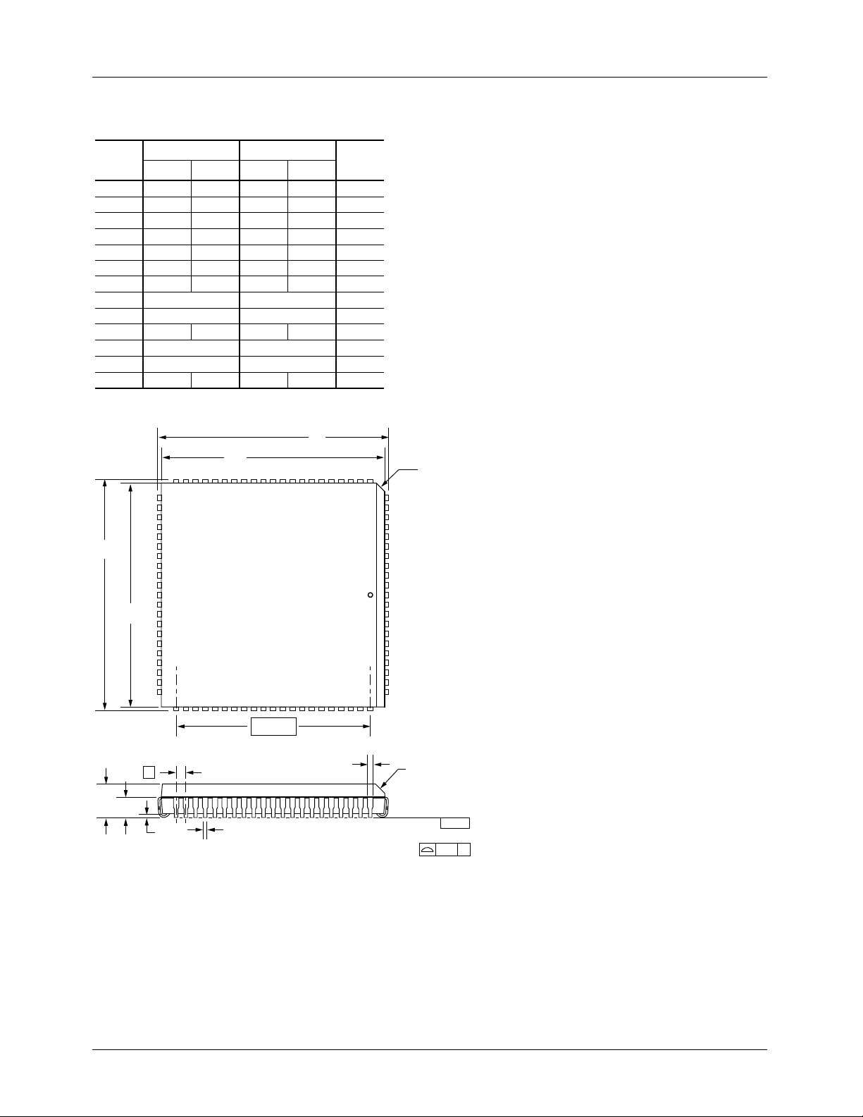
TMC22091/TMC22191 PRODUCT SPECIFICATION
Mechanical Dimensions – 84-Lead PLCC Package
Symbol
A .165 .200 4.19 5.08
A1 .090 .130 2.29 3.30
A2 .020 .51
B .013 .021 .33 .53
B1 .026 .032 .66 .81
D/E 1.185 1.195 30.10 30.35
D1/E1 1.150 1.158 29.21 29.41
D3/E3 1.000 BSC 25.40 BSC
e
J .042 .056 1.07 1.42 2
ND/NE 21 21
N
ccc .004 0.10— —
Inches
Min. Max. Min. Max.
— —
.050 BSC 1.27 BSC
84 84
Millimeters
E1
D
Notes:
Notes
3
E
All dimensions and tolerances conform to ANSI Y14.5M-1982.
1.
Corner and edge chamfer = 45°.
2.
Dimension D1 and E1 do not include mold protrusion. Allowable
3.
protrusion is .101" (.25mm).
J
D1
D3/E3
e
A
A1
A2
B
B1
LEAD COPLANARITY
J
-C-
ccc
C
58
Page 59
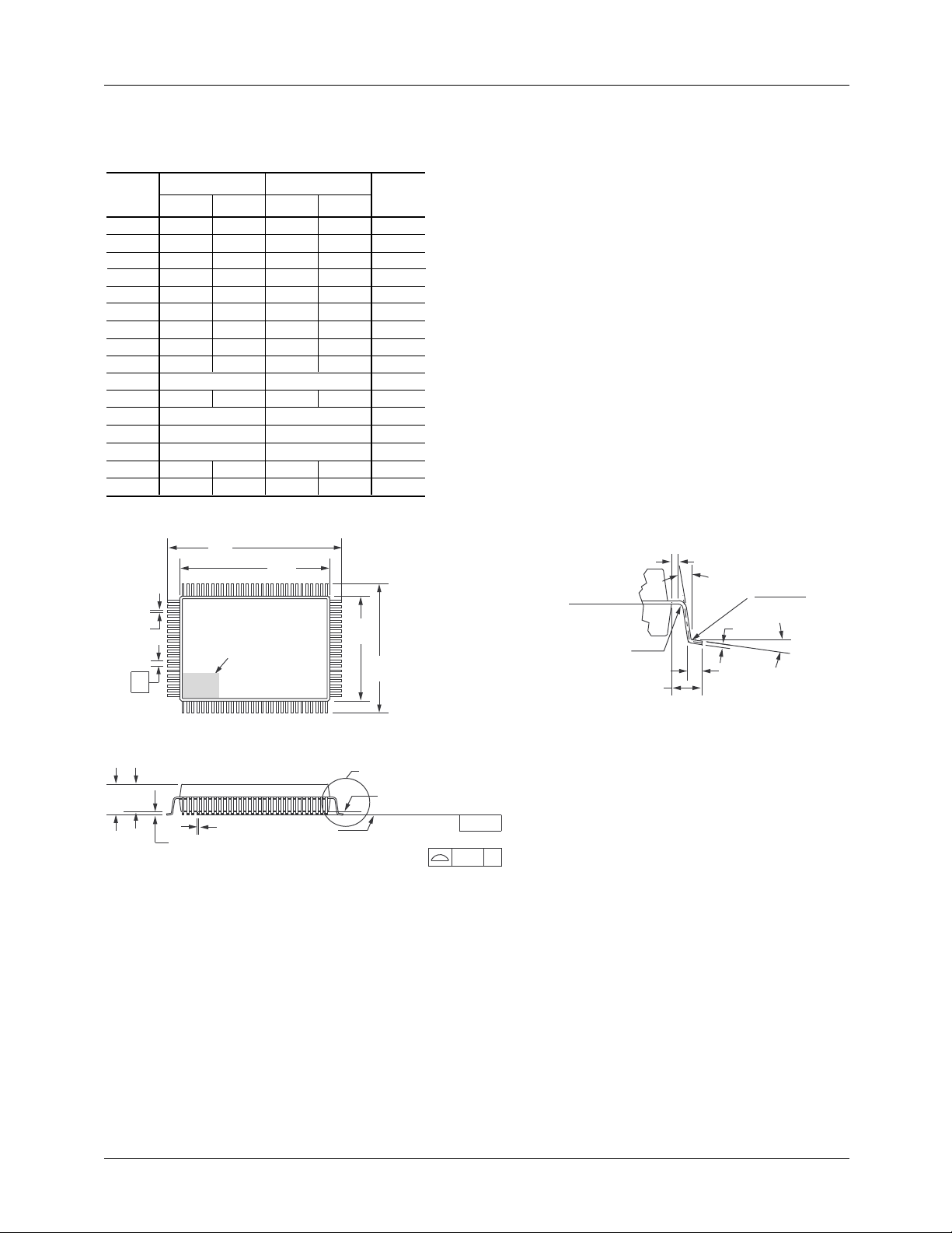
PRODUCT SPECIFICATION TMC22091/TMC22191
Mechanical Dimensions
100 Lead MQFP Package – 3.2mm Footprint
Symbol
A — .134 — 3.40
A1 .010 — .25 —
A2 .100 .120 2.55 3.05
B .008 3, 5
C .005 .13
D .904 .923 22.95 23.45
D1 .783 .791 19.90 20.10
E .667 .687 16.95 17.45
E1 .547 .555 13.90 14.10
e
L .028 .040 .73 1.03
N
ND
NE
α 0° 7° 0° 7°
ccc
B
e
Inches
Min. Max. Min. Max.
.015 .38
.009 .23
.0256 BSC .65 BSC
100 100
30 30
20 20
— .004 — .12
D
Pin 1 Indentifier
Millimeters
.22
D1
Notes
E1
E
Notes:
All dimensions and tolerances conform to ANSI Y14.5M-1982.
1.
Controlling dimension is millimeters.
2.
Dimension "B" does not include dambar protrusion. Allowable
3.
dambar protrusion shall be .08mm (.003in.) maximum in excess of
the "B" dimension. Dambar cannot be located on the lower radius
or the foot.
"L" is the length of terminal for soldering to a substrate.
5
4
4.
"B" & "C" includes lead finish thickness.
5.
Datum Plane
.13 (.005) R Min.
0.076" (1.95mm) Ref
Lead Detail
.20 (.008) Min.
0° Min.
C
L
.13 (.30)
.005 (.012)
α
R
A A2
A1
B
Seating Plane
See Lead Detail
Base Plane
-C-
Lead Coplanarity
ccc C
59
Page 60

TMC22091/TMC22191 PRODUCT SPECIFICATION
Ordering Information
Product Number Temperature Range Screening Package Package Marking
TMC22091KHC TA = 0°C to 70°C Commercial 100-Lead MQFP 22091KHC
TMC22091R0C TA = 0°C to 70°C Commercial 84-Lead PLCC 22091R0C
TMC22191KHC TA = 0°C to 70°C Commercial 100-Lead MQFP 22191KHC
TMC22191R0C TA = 0°C to 70°C Commercial 84-Lead PLCC 22191R0C
LIFE SUPPORT POLICY
FAIRCHILD’S PRODUCTS ARE NOT AUTHORIZED FOR USE AS CRITICAL COMPONENTS IN LIFE SUPPORT DEVICES
OR SYSTEMS WITHOUT THE EXPRESS WRITTEN APPROVAL OF THE PRESIDENT OF FAIRCHILD SEMICONDUCTOR
CORPORATION. As used herein:
1. Life support devices or systems are devices or systems
which, (a) are intended for surgical implant into the body,
or (b) support or sustain life, and (c) whose failure to
perform when properly used in accordance with
instructions for use provided in the labeling, can be
reasonably expected to result in a significant injury of the
user.
2. A critical component in any component of a life support
device or system whose failure to perform can be
reasonably expected to cause the failure of the life support
device or system, or to affect its safety or effectiveness.
www.fairchildsemi.com
6/12/98 0.0m 002
1998 Fairchild Semiconductor Corporation
Stock# DS70022091
 Loading...