

Page 1
现货库存、技术资料、百科信息、热点资讯,精彩尽在鼎好!
TLP3021(S),TLP3022(S),TLP3023(S)
TOSHIBA PHOTOCOUPLER GaAs IRED & PHOTO-TRIAC
TLP3021(S),TLP3022(S),TLP3023(S)
OFFICE MACHINE
HOUSEHOLD USE EQUIPMENT
TRIAC DRIVER
SOLID STATE RELAY
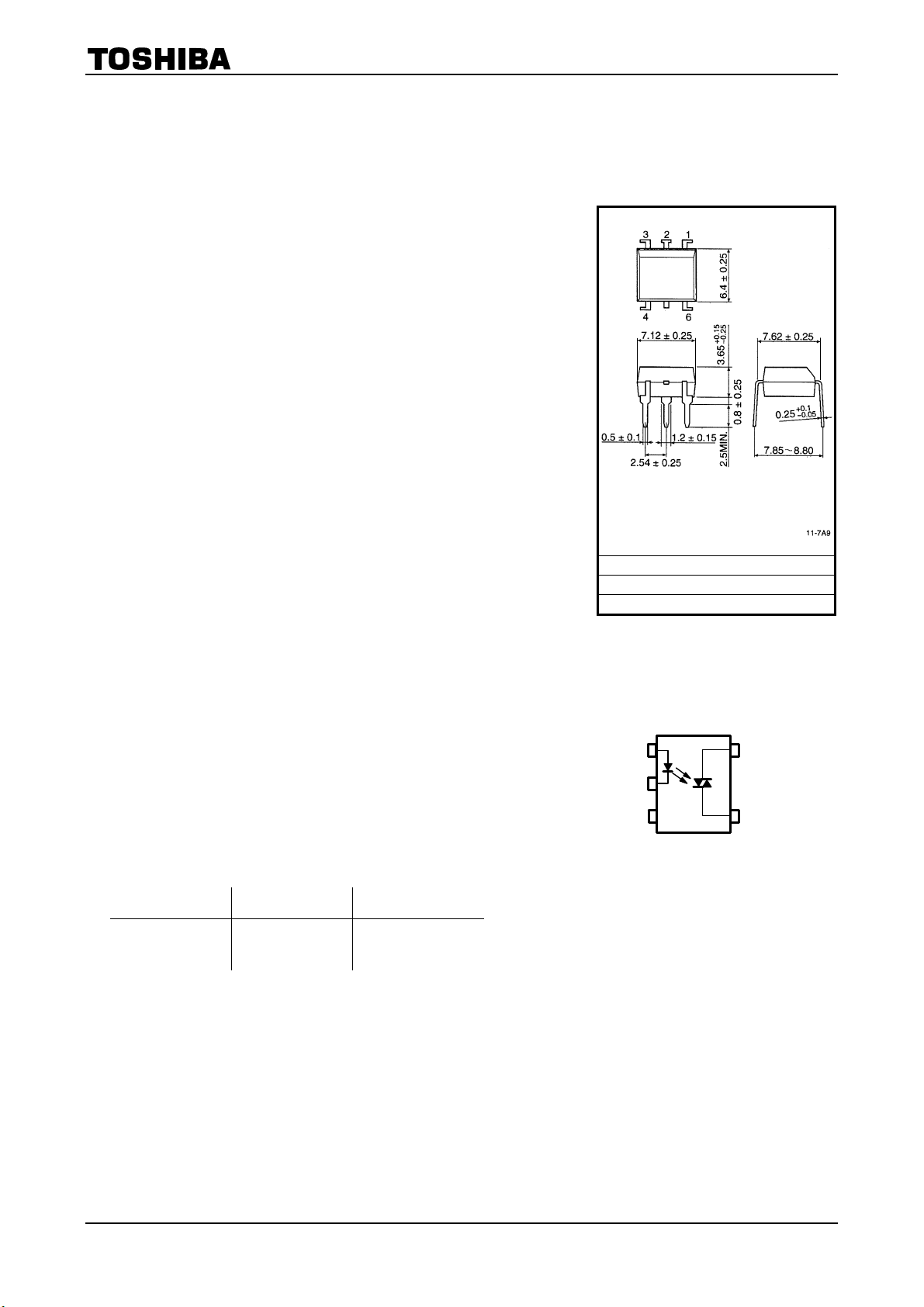
The TOSHIBA TLP3021 (S), TLP3022 (S) and TLP3023 (S) consist of
photo-triac optically coupled to a gallium arsenide infrared emitting diode
in a six lead plastic DIP.
z Peak Off-State Voltage : 400 V (min)
z Trigger LED Current : 15 mA (max) (TLP3021(S))
10 mA (max) (TLP3022(S))
5 mA (max) (TLP3023(S))
z On-State Current : 100 mA (max)
z Isolation Voltage : 5000Vrms(Min)
z UL Recognized : UL1577,File No.E67349
z SEMKO Approved : SS EN60065
SS EN60950, File No.9841105
z BSI Approved : BS EN60065, File No.8385
BS EN60950, File No.8386
z Option (D4) type
VDE approved: DIN EN60747-5-2
Approved No. 40009302
Maximum operating insulation voltage: 890V
Highest permissible over voltage: 8000V
(Note):When a EN60747-5-2 approved type is needed,
please designate the "Option (D4)"
z Construction Mechanical Rating
Creepage Distance
Clearance
Insulation Thickness
7.62 mm pich
Standard Type
7.0 mm (Min)
7.0 mm (Min)
0.5 mm (Min)
PK
10.16 mm pich
TLPxxxxF Type
8.0 mm (Min)
8.0 mm (Min)
0.5 mm (Min)
PK
JEDEC ―
EIAJ ―
TOSHIBA 11-7A9
Weight : 0.39g
Pin Configuration
(top view)
1
2
3
1: Anode
2: Csthode
3: N.C.
4:Terminal 1
6:Terminal 2
Unit: mm
6
4
1
2007-10-01
Page 2
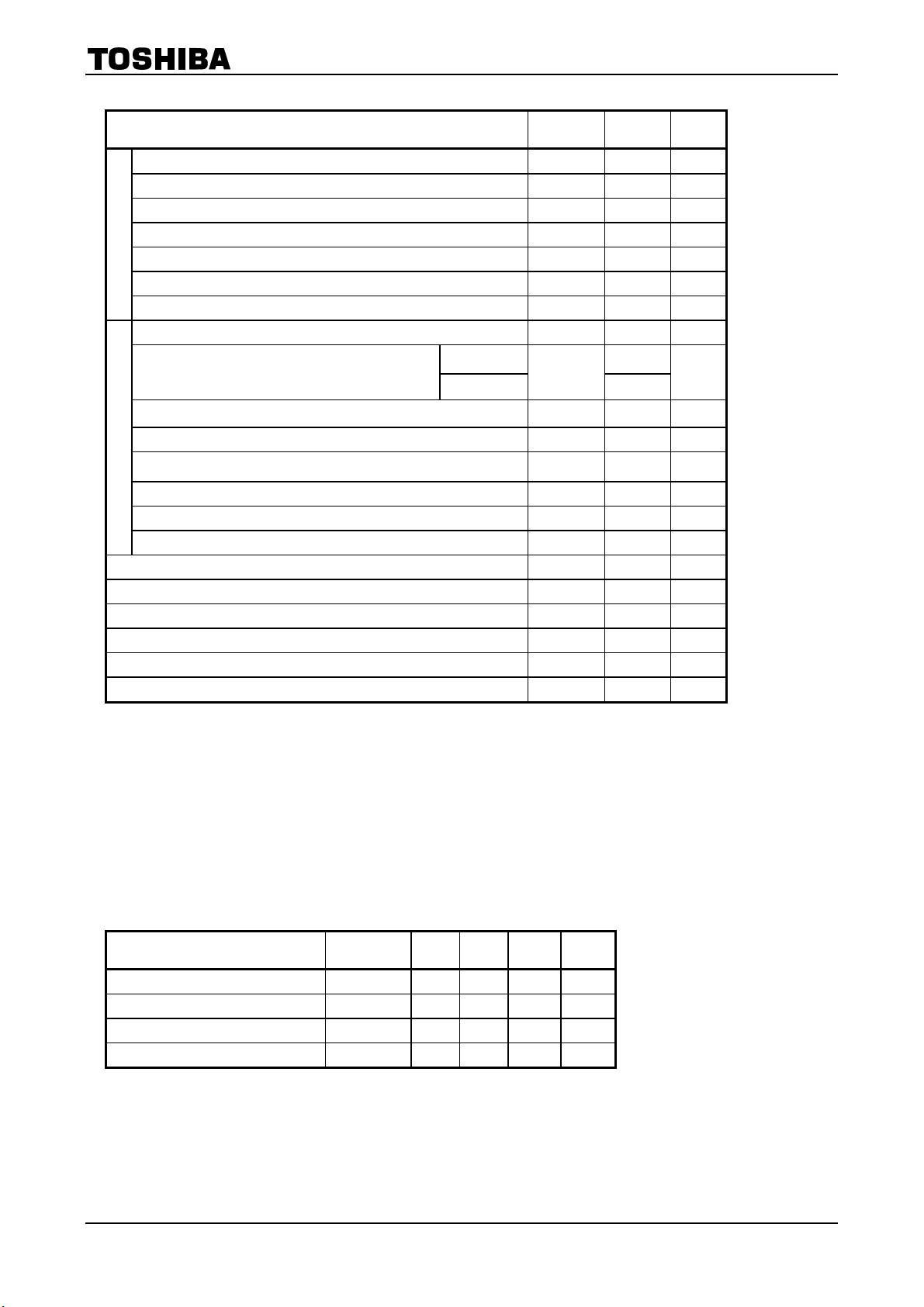
Absolute Maximum Ratings (Ta=25°C)
CHARACTERISTIC SYMBOL RATING UNIT
TLP3021(S),TLP3022(S),TLP3023(S)
Forward Current I
Forward Current Derating (Ta≥53°C) ∆IF /°C −0.7 mA /°C
Peak Forward Current (100μs pulse, 100pps) I
LED
Power Dissipation PD 100 mW
Power Dissipation Derating (Ta≥25°C) ∆PD /°C -1.0 mW/°C
Reverse Voltage V
Junction Temperature Tj 125 °C
Off-State Output Terminal Voltage V
On-State RMS Current
On-State Current Derating (Ta≥25°C) ∆IT/°C -1.1 mA /°C
Peak On-State Current (100μs pulse, 120pps) I
Peak Nonrepetitive Surge Current (Pw=10ms,DC=10%) I
DETECTOR
Power Dissipation PD 300
Power Dissipation Derating (Ta≥25°C) ∆PD /°C -4.0
Junction Temperature T
Storage Temperature Range T
Operating Temperature Range T
Lead Soldering Temperature (10s) T
Total Package Power Dissipation PT 330
Total Package Power Dissipation Derating (Ta≥25°C) ∆PT/°C -4.4
Isolation Voltage (AC,1min. , R.H.≤60%) (Note 2) BV
Ta=25°C 100
Ta=70°C
F
FP
R
DRM
I
T(RMS)
TP
1.2 A
TSM
j
stg
opr
sol
S
50 mA
1 A
5 V
400 V
50
2 A
115
−55~150 °C
−40~100 °C
260
5000 Vrms
mA
mW
mW/°C
°C
°C
mW
mW /°C
Note: Using continuously under heavy loads (e.g. the application of high temperature/current/voltage and the
significant change in temperature, etc.) may cause this product to decrease in the reliability significantly even
if the operating conditions (i.e. operating temperature/current/voltage, etc.) are within the absolute maximum
ratings.
Please design the appropriate reliability upon reviewing the Toshiba Semiconductor Reliability Handbook
(“Handling Precautions”/“Derating Concept and Methods”) and individual reliability data (i.e. reliability test
report and estimated failure rate, etc).
(Note 2) Device considered a two terminal device :Pins1,2 and 3 shorted together and pin4 and pin6 shorted
together.
Recommended Operating Conditions
CHARACTERISTIC SYMBOL MIN. TYP. MAX. UNIT
Supply Voltage V
Forward Current I
Peak On-State Current I
Operating Temperature T
AC
F*
TP
opr
Note: Recommended operating conditions are given as a design guideline to obtain expected performance of the
device. Additionally, each item is an independent guideline respectively. In developing designs using this
product, please confirm specified characteristics shown in this document.
*In The case of TLP3022
— —
15 20 25 mA
— —
−25 — 85 °C
120 Vac
1 A
2
2007-10-01
Page 3
TLP3021(S),TLP3022(S),TLP3023(S)
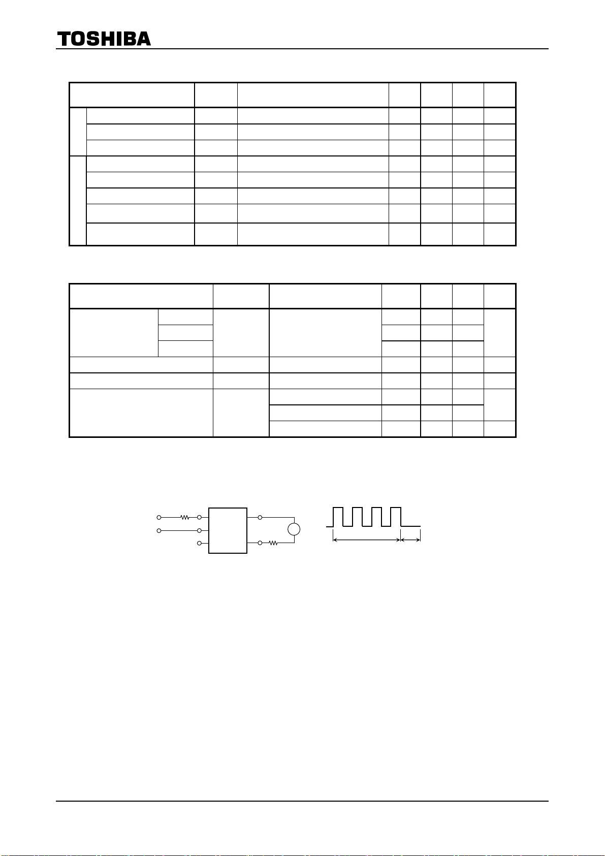
Individual Electrical Characteristics (Ta=25°C)
CHARACTERISTIC SYMBOL TEST CONDITION MIN. TYP. MAX. UNIT
Forward Voltage V
Reverse Current IR VR = 5 V
LED
Capacitance C
Peak Off-State Current I
Peak On-State Voltage V
Holding Current I
Critical Rate of Rise of
Off-State Voltage
Critical Rate of Rise of
DETECTOR
Commutating Voltage
DRM
dv/dt
dv/dt(c)
IF = 10 mA 1.0 1.15 1.3 V
F
V = 0, f=1MHz
T
V
=400V
DRM
ITM=100mA
TM
H
Vin=120Vrms , Ta=85°C (Fig.1) 200 500
Vin=30Vrms , IT=15mA (Fig.1) — 0.2
—
Coupled Electrical Characteristics (Ta=25°C)
CHARACTERISTIC SYMBOL TEST CONDITION MIN. TYP. MAX. UNIT
TLP3021(S)
Trigger LED Current
Capacitance (Input to Output) C
Isolation Resistance RS VS=500V(R.H.≤60%)
Isolation Voltage BV
TLP3022(S)
TLP3023(S)
I
FT
VT=3V
VS=0 , f=1MHz
S
AC , 1minute 5000 —
AC , 1second,in oil
S
DC , 1minute,in oil
— —
—
—
—
—
—
—
—
—
10
5×10
—
—
10 μA
10 — pF
10 1000 nA
1.7 3.0 V
0.6
— 15
— 5
0.8
1014
—
—
— V/μs
5 10
—
—
mA
V/μs
mA
pF
Ω
—
Vrms
10000
10000
—
—
Vdc
Fig. 1 dv / dt test circuit
V
CC
+
120Ω
−
6
1
2
4
3
R
L
2kΩ
Vin
~
dv / dt(c)
R
in
+5V,VCC
0V
dv / dt
3
2007-10-01
Page 4
TLP3021(S),TLP3022(S),TLP3023(S)
4
2007-10-01
Page 5
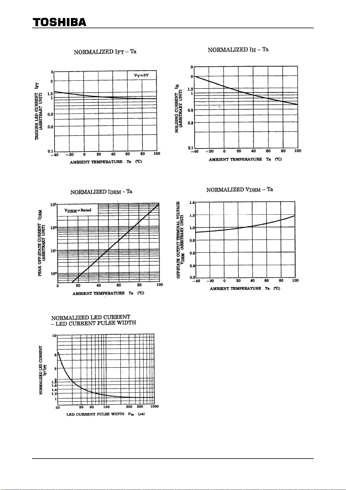
TLP3021(S),TLP3022(S),TLP3023(S)
5
2007-10-01
Page 6
TLP3021(S),TLP3022(S),TLP3023(S)
RESTRICTIONS ON PRODUCT USE
• The information contained herein is subject to change without notice.
• TOSHIBA is continually working to improve the quality and reliability of its products. Nevertheless, semiconductor
devices in general can malfunction or fail due to their inherent electrical sensitivity and vulnerability to physical
stress. It is the responsibility of the buyer, when utilizing TOSHIBA products, to comply with the standards of
safety in making a safe design for the entire system, and to avoid situations in which a malfunction or failure of
such TOSHIBA products could cause loss of human life, bodily injury or damage to property.
In developing your designs, please ensure that TOSHIBA products are used within specified operating ranges as
set forth in the most recent TOSHIBA products specifications. Also, please keep in mind the precautions and
conditions set forth in the “Handling Guide for Semiconductor Devices,” or “TOSHIBA Semiconductor Reliability
Handbook” etc.
• The TOSHIBA products listed in this document are intended for usage in general electronics applications
(computer, personal equipment, office equipment, measuring equipment, industrial robotics, domestic appliances,
etc.).These TOSHIBA products are neither intended nor warranted for usage in equipment that requires
extraordinarily high quality and/or reliability or a malfunction or failure of which may cause loss of human life or
bodily injury (“Unintended Usage”). Unintended Usage include atomic energy control instruments, airplane or
spaceship instruments, transportation instruments, traffic signal instruments, combustion control instruments,
medical instruments, all types of safety devices, etc.. Unintended Usage of TOSHIBA products listed in his
document shall be made at the customer’s own risk.
• The products described in this document shall not be used or embedded to any downstream products of which
manufacture, use and/or sale are prohibited under any applicable laws and regulations.
• The information contained herein is presented only as a guide for the applications of our products. No
responsibility is assumed by TOSHIBA for any infringements of patents or other rights of the third parties which
may result from its use. No license is granted by implication or otherwise under any patents or other rights of
TOSHIBA or the third parties.
20070701-EN
• GaAs(Gallium Arsenide) is used in this product. The dust or vapor is harmful to the human body. Do not break,
cut, crush or dissolve chemically.
• Please contact your sales representative for product-by-product details in this document regarding RoHS
compatibility. Please use these products in this document in compliance with all applicable laws and regulations
that regulate the inclusion or use of controlled substances. Toshiba assumes no liability for damage or losses
occurring as a result of noncompliance with applicable laws and regulations.
6
2007-10-01
 Loading...