

Page 1

TLC320AD58C
Data Manual
Sigma-Delta Stereo Analog-to-Digital Converter
SLAS102
May 1995
Printed on Recycled Paper
Page 2

IMPORTANT NOTICE
T exas Instruments (TI) reserves the right to make changes to its products or to discontinue any
semiconductor product or service without notice, and advises its customers to obtain the latest
version of relevant information to verify , before placing orders, that the information being relied
on is current.
TI warrants performance of its semiconductor products and related software to the specifications
applicable at the time of sale in accordance with TI’s standard warranty . T esting and other quality
control techniques are utilized to the extent TI deems necessary to support this warranty.
Specific testing of all parameters of each device is not necessarily performed, except those
mandated by government requirements.
Certain applications using semiconductor products may involve potential risks of death,
personal injury , or severe property or environmental damage (“Critical Applications”).
TI SEMICONDUCTOR PRODUCTS ARE NOT DESIGNED, INTENDED, AUTHORIZED, OR
WARRANTED TO BE SUITABLE FOR USE IN LIFE-SUPPORT APPLICATIONS, DEVICES
OR SYSTEMS OR OTHER CRITICAL APPLICATIONS.
Inclusion of TI products in such applications is understood to be fully at the risk of the customer.
Use of TI products in such applications requires the written approval of an appropriate TI officer .
Questions concerning potential risk applications should be directed to TI through a local SC
sales office.
In order to minimize risks associated with the customer’s applications, adequate design and
operating safeguards should be provided by the customer to minimize inherent or procedural
hazards.
TI assumes no liability for applications assistance, customer product design, software
performance, or infringement of patents or services described herein. Nor does TI warrant or
represent that any license, either express or implied, is granted under any patent right, copyright,
mask work right, or other intellectual property right of TI covering or relating to any combination,
machine, or process in which such semiconductor products or services might be or are used.
Copyright 1995, Texas Instruments Incorporated
Page 3

Contents
Section Title Page
1 Introduction 1–1. . . . . . . . . . . . . . . . . . . . . . . . . . . . . . . . . . . . . . . . . . . . . . . . . . . . . . . . . . . . . . .
1.1 Features 1–1. . . . . . . . . . . . . . . . . . . . . . . . . . . . . . . . . . . . . . . . . . . . . . . . . . . . . . . . . . . . . .
1.2 Functional Block Diagram 1–1. . . . . . . . . . . . . . . . . . . . . . . . . . . . . . . . . . . . . . . . . . . . . . .
1.3 Terminal Assignments 1–2. . . . . . . . . . . . . . . . . . . . . . . . . . . . . . . . . . . . . . . . . . . . . . . . . .
1.4 Ordering Information 1–2. . . . . . . . . . . . . . . . . . . . . . . . . . . . . . . . . . . . . . . . . . . . . . . . . . .
1.5 Terminal Functions 1–2. . . . . . . . . . . . . . . . . . . . . . . . . . . . . . . . . . . . . . . . . . . . . . . . . . . . .
2 Detailed Description 2–1. . . . . . . . . . . . . . . . . . . . . . . . . . . . . . . . . . . . . . . . . . . . . . . . . . . . . . .
2.1 Power-Down and Reset Functions 2–1. . . . . . . . . . . . . . . . . . . . . . . . . . . . . . . . . . . . . . .
2.1.1 Power Down 2–1. . . . . . . . . . . . . . . . . . . . . . . . . . . . . . . . . . . . . . . . . . . . . . . . . . . .
2.1.2 Reset Function 2–1. . . . . . . . . . . . . . . . . . . . . . . . . . . . . . . . . . . . . . . . . . . . . . . . . .
2.2 Differential Input 2–2. . . . . . . . . . . . . . . . . . . . . . . . . . . . . . . . . . . . . . . . . . . . . . . . . . . . . . .
2.3 Sigma-Delta Modulator 2–3. . . . . . . . . . . . . . . . . . . . . . . . . . . . . . . . . . . . . . . . . . . . . . . . .
2.4 Decimation Filter 2–3. . . . . . . . . . . . . . . . . . . . . . . . . . . . . . . . . . . . . . . . . . . . . . . . . . . . . . .
2.5 High-Pass Filter 2–3. . . . . . . . . . . . . . . . . . . . . . . . . . . . . . . . . . . . . . . . . . . . . . . . . . . . . . .
2.6 Master-Clock Circuit 2–3. . . . . . . . . . . . . . . . . . . . . . . . . . . . . . . . . . . . . . . . . . . . . . . . . . . .
2.7 T est 2–3. . . . . . . . . . . . . . . . . . . . . . . . . . . . . . . . . . . . . . . . . . . . . . . . . . . . . . . . . . . . . . . . . .
2.8 Serial Interface 2–3. . . . . . . . . . . . . . . . . . . . . . . . . . . . . . . . . . . . . . . . . . . . . . . . . . . . . . . .
2.8.1 Master Mode 2–4. . . . . . . . . . . . . . . . . . . . . . . . . . . . . . . . . . . . . . . . . . . . . . . . . . . .
2.8.2 Slave Mode 2–5. . . . . . . . . . . . . . . . . . . . . . . . . . . . . . . . . . . . . . . . . . . . . . . . . . . . .
3 Specifications 3–1. . . . . . . . . . . . . . . . . . . . . . . . . . . . . . . . . . . . . . . . . . . . . . . . . . . . . . . . . . . . .
3.1 Absolute Maximum Ratings Over Operating Free-Air Temperature Range 3–1. . . . .
3.2 Recommended Operating Conditions 3–1. . . . . . . . . . . . . . . . . . . . . . . . . . . . . . . . . . . . .
3.3 Electrical Characteristics 3–2. . . . . . . . . . . . . . . . . . . . . . . . . . . . . . . . . . . . . . . . . . . . . . . .
3.3.1 Digital Interface, T
3.3.2 Analog Interface 3–2. . . . . . . . . . . . . . . . . . . . . . . . . . . . . . . . . . . . . . . . . . . . . . . . .
3.3.3 Channel Characteristics, T
f
= 48 kHz 3–3. . . . . . . . . . . . . . . . . . . . . . . . . . . . . . . . . . . . . . . . . . . . . . . . . . . . . .
3.4 Switching Characteristics 3–3. . . . . . . . . . . . . . . . . . . . . . . . . . . . . . . . . . . . . . . . . . . . . . .
s
= 25°C, AVDD = DVDD = 5 V 3–2. . . . . . . . . . . . . . . . . . . .
A
= 25°C, AVDD = DVDD = 5 V,
A
4 Parameter Measurement Information 4–1. . . . . . . . . . . . . . . . . . . . . . . . . . . . . . . . . . . . . . . .
5 Application Information 5–1. . . . . . . . . . . . . . . . . . . . . . . . . . . . . . . . . . . . . . . . . . . . . . . . . . . .
Appendix A Mechanical Data A-1. . . . . . . . . . . . . . . . . . . . . . . . . . . . . . . . . . . . . . . . . . . . . . .
iii
Page 4

List of Illustrations
Figure Title Page
2–1. Power-Down Timing Relationships 2–2. . . . . . . . . . . . . . . . . . . . . . . . . . . . . . . . . . . . . . . . . . .
2–2. Differential Analog Input Configuration 2–2. . . . . . . . . . . . . . . . . . . . . . . . . . . . . . . . . . . . . . .
2–3. Serial Master Transfer Modes 2–5. . . . . . . . . . . . . . . . . . . . . . . . . . . . . . . . . . . . . . . . . . . . . . .
2–4. Serial Slave Transfer Modes 2–6. . . . . . . . . . . . . . . . . . . . . . . . . . . . . . . . . . . . . . . . . . . . . . . .
4–1. SCLK to Fsync and DOUT – Master Mode 3 4–1. . . . . . . . . . . . . . . . . . . . . . . . . . . . . . . . . .
4–2. SCLK to Fsync, DOUT, and LRClk – Master Modes 4 and 6 4–1. . . . . . . . . . . . . . . . . . . . .
4–3. SCLK to Fsync, DOUT, and LRClk – Master Mode 5 4–1. . . . . . . . . . . . . . . . . . . . . . . . . . .
4–4. SCLK to Fsync, DOUT, and LRClk – Master Mode 7 4–2. . . . . . . . . . . . . . . . . . . . . . . . . . .
4–5. SCLK to LRClk and DOUT – Slave Mode 0, Fsync High 4–2. . . . . . . . . . . . . . . . . . . . . . . .
4–6. SCLK to Fsync, LRClk, and DOUT – Slave Mode 2, Fsync Controlled 4–2. . . . . . . . . . . .
5–1. TLC320AD58C Configuration Schematic 5–2. . . . . . . . . . . . . . . . . . . . . . . . . . . . . . . . . . . . .
5–2. TLC320AD58C External Digital Timing and Control-Signal Generation Schematic 5–3.
5–3. TLC320AD58C External Analog Input Buffer Schematic 5–4. . . . . . . . . . . . . . . . . . . . . . . .
List of Tables
Table Title Page
2–1. Master-Clock to Sample-Rate Comparison 2–3. . . . . . . . . . . . . . . . . . . . . . . . . . . . . . . . . .
iv
Page 5
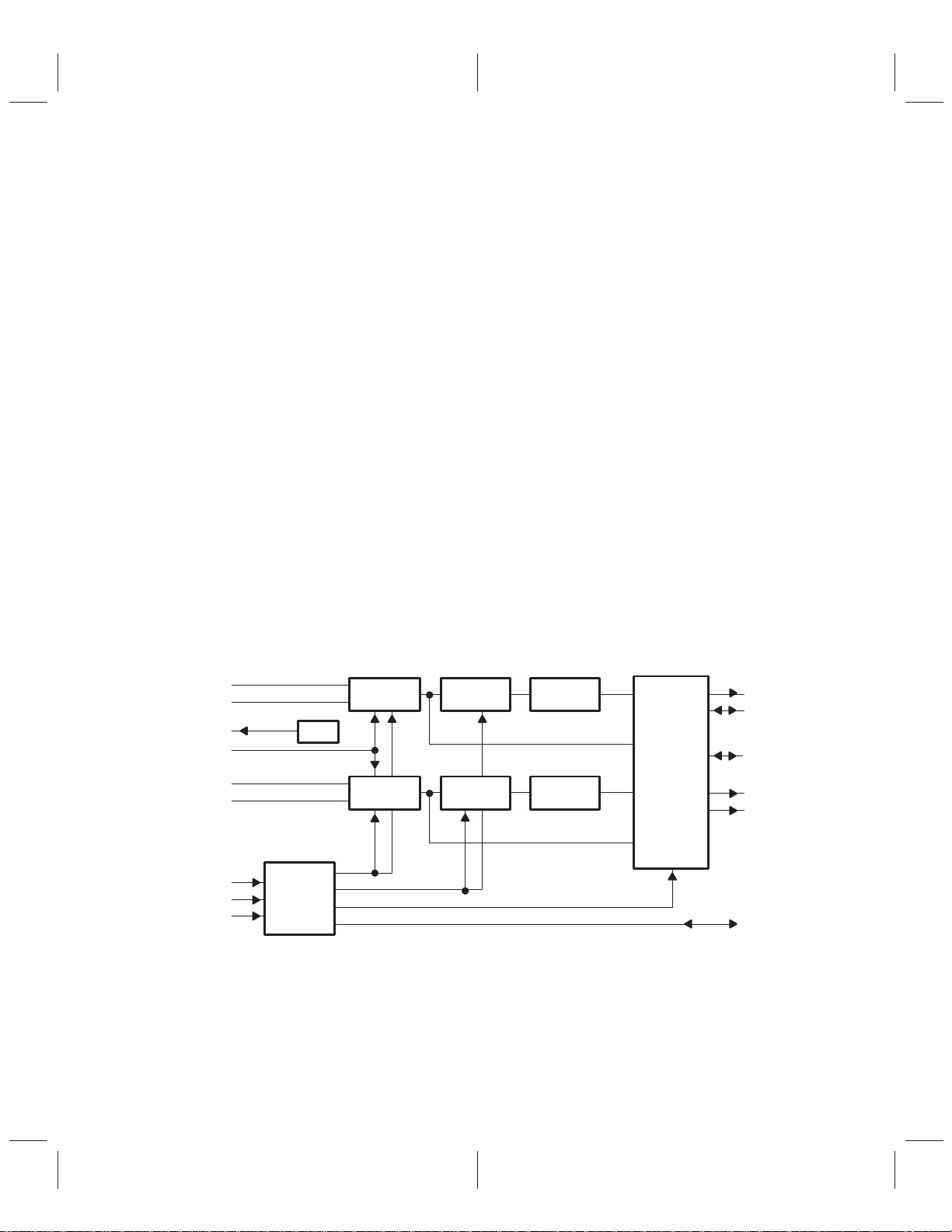
1 Introduction
The TLC320AD58C provides high-resolution signal conversion from analog to digital using oversampling
sigma-delta technology. This device consists of two synchronous conversion paths. Also included is a
decimation filter after the modulator as shown in the functional block diagram. Other functions provide
analog filtering and on-chip timing and control.
A functional block diagram of the TLC320AD58C is included in Section 1.2. Each block is described in the
detailed description section.
1.1 Features
• Single 5-V Power Supply
• Sample Rates up to 48 kHz
• 18-Bit Resolution
• Signal-to-Noise Ratio (EIAJ) of 97 dB
• Dynamic Range of 95 dB
• Total Signal-to-Noise+Distortion of 95 dB
• Internal Reference Voltage (V
• Serial-Port Interface
• Differential Architecture
• Power Dissipation of 200 mW. Power-Down Mode for Low-Power Applications
• One-Micron Advanced LinEPIC1Z Process
1.2 Functional Block Diagram
ref
)
INLP
INLM
REFO
REFI
INRP
INRM
MCLK
CMODE
MODE(0–2)
CONTROL
VREF
Sigma-Delta
Modulator
Sigma-Delta
Modulator
Decimation
Filter
Decimation
Filter
LinEPIC1Z is a trademark of Texas Instruments Incorporated.
High-Pass
Filter
High-Pass
Filter
Serial
Interface
DOUT
Fsync
LRClk
OSFR
OSFL
SCLK
1–1
Page 6
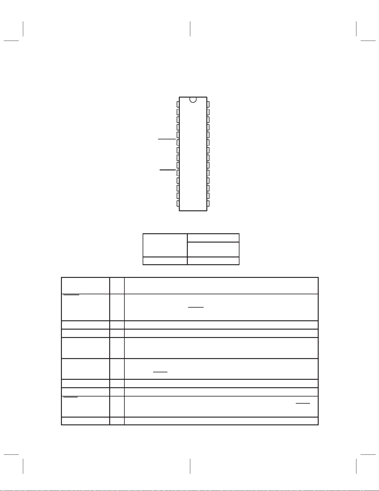
1.3 Terminal Assignments
I/O
DESCRIPTION
DW PACKAGE
(TOP VIEW)
INLP
1
INLM
REFI
AV
AV
AnaPD
TEST1
MODE2
OSFL
DigPD
TEST2
CMODE
MODE0
LRClk
NC – No internal connection
DD
SS
2
3
4
5
6
7
8
9
10
11
12
13
14
28
27
26
25
24
23
22
21
20
19
18
17
16
15
INRP
INRM
REFO
LGND
Vlogic
NC
MODE1
OSFR
MCLK
DV
SS
DV
DD
Fsync
DOUT
SCLK
1.4 Ordering Information
PACKAGE
T
A
0°C to 70°C TLC320AD58CDW
SMALL OUTLINE
(DW)
1.5 Terminal Functions
TERMINAL
NAME NO.
AnaPD 6 I Analog power-down mode. The analog power-down mode disables the analog
AV
DD
AV
SS
CMODE 12 I Clock mode. CMODE is used to select between two methods of determining the master
DOUT 16 O Data output. DOUT is used to transmit the sigma-delta audio ADC output data to a DSP
DV
DD
DV
SS
DigPD 10 I Digital power-down mode. The digital power-down mode shuts down the digital filters and
Fsync 17 I/O Frame sync. Frame sync is used to designate the valid data from the ADC.
4 I Analog supply voltage
5 I Analog ground
18 I Digital supply voltage
19 I Digital ground
modulators. The single-bit modulator outputs become invalid, rendering the outputs of the
digital filters invalid. When AnaPD
resumed.
clock frequency. When CMODE is high, the master clock input is 384× the conversion
frequency. When CMODE is low , the master clock input is 256× the conversion frequency .
serial port or other compatible serial interface and is synchronized to SCLK. This output
is low when DigPD
clock generators. All digital outputs are brought to unasserted states. When DigPD
pulled high, normal operation of the device is resumed.
is high.
is pulled high, normal operation of the device is
is
1–2
Page 7
1.5 Terminal Functions (Continued)
I/O
DESCRIPTION
TERMINAL
NAME NO.
INLM 2 I Inverting input to left analog input amplifier
INLP 1 I Noninverting input to left analog input amplifier
INRM 27 I Inverting input to right analog input amplifier
INRP 28 I Noninverting input to right analog input amplifier
LGND 25 I Logic power supply ground for analog modulator
LRClk 14 I/O Left/right clock. LRClk signifies whether the serial data is associated with the left channel
MCLK 20 I Master clock. MCLK is used to derive all the key logic signals of the sigma-delta audio
MODE(0–2) 13, 22,8I Serial modes. MODE(0–2) configure this device for many different modes of operation.
OSFL,
OSFR
SCLK 15 I/O Shift clock. If SCLK is configured as an input, SCLK is used to clock serial data out of
TEST1 7 I Test mode 1. TEST1 should be low for normal operation.
TEST2 11 I Test mode 2. TEST2 should be low for normal operation.
REFI 3 I Input voltage for modulator reference (normally connected to REFO, terminal 26).
REFO 26 I Internal voltage reference
Vlogic 24 I Logic power supply voltage (5 V) for analog modulator
9, 21 O Over scale flag left/right. If the left/right channel digital output exceeds full scale output
ADC (when LRClk is high) or the right channel ADC (when LRClk is low). LRClk is low
when DigPD
ADC. The nominal input frequency range is 18.432 MHz to 256 kHz.
The different configurations are:
Master versus slave
16 bit versus 18 bit
MSB first versus LSB first
Slave: Fsync controlled versus Fsync high
Each of these modes is described in the serial interface section along with timing
diagrams.
MODE MASTER/ MSB/LSB
0 1 2 SLAVE BITS FIRST
0 0 0 slave up to 18 MSB
0 0 1 slave 18 LSB
0 1 0 slave up to 18 MSB
0 1 1 master 16 MSB
1 0 0 master 18 MSB
1 0 1 master 18 LSB
1 1 0 master 16 MSB
1 1 1 master 16 LSB
range for two consecutive conversions, this flag is set high for 4096 LRClk periods.
OSFL and OSFR are low when DigPD
the sigma-delta audio ADC. If SCLK is configured as an output, SCLK stops clocking
when DigPD
is low.
is low.
is low.
1–3
Page 8

1–4
Page 9

2 Detailed Description
The sigma-delta converter allows for simple antialias external filtering. Typically, a first order RC filter is
sufficient.
2.1 Power-Down and Reset Functions
2.1.1 Power Down
The power-down state is comprised of a separate digital and analog power down. The power consumption
of each is detailed in the electrical characteristics section.
The digital power-down mode shuts down the digital filters and clock generators. All digital outputs are set
to an unasserted level. When the digital power-down terminal is pulled high, normal operation of the device
is initiated. In slave mode, the conversion process must synchronize to an input on the LRClk terminal as
well as the SCLK terminal. Therefore, the conversion process is not initiated until the first rising edges of
both SCLK and LRClk are detected after DigPD
conversions are performed at a fixed LRClk rate [MCLK/256 (CMODE low) or MCLK/384 (CMODE high)]
after the initial synchronization. After the digital power-down terminal is brought high, the output of the digital
filters remains invalid for 50 LRClk cycles [see Figures 2–1(a) and 2–1(b)].
In master mode, LRClk is an output; therefore, the conversion process initiates based on internal timing.
The first valid data out occurs as shown in Figure 2–1(c).
The analog power-down mode disables the analog modulators. The single-bit modulator outputs become
invalid which renders the outputs of the digital filters invalid. When the analog power-down terminal is
brought high, the modulators are brought back online; however, the outputs of the digital filters require 50
LRClk cycles for valid results.
2.1.2 Reset Function
The conversion process is not initiated until the first rising edges of both SCLK and LRClk are detected after
DigPD is pulled high. This synchronizes the conversion cycle; all conversions are performed at a fixed LRClk
rate [MCLK/256 (CMODE low) or MCLK/384 (CMODE high)] after the initial synchronization.
is pulled high. This synchronizes the conversion cycle; all
2–1
Page 10

DigPD
LRClk
t
su5
Slave-Mode Digital Power Down
DOUT
DigPD
LRClk
DOUT
AnaPD
DOUT
t
su6
(a)
Master-Mode Digital Power Down
(b)
t
d1
(c)
Analog Power Down
Data Valid
Data Valid
Figure 2–1. Power-Down Timing Relationships
2.2 Differential Input
The input is differential in order to provide common-mode noise rejection and increase the input dynamic
range. Figure 2–2 shows the analog input signals used in a differential configuration to achieve a
6.4 V
differential swing with a 3.2 V
I(PP)
configuration are shown in the application information section.
swing per input line. Both a differential and a single-ended
I(PP)
TLC320AD58
2–2
4.1 V
2.5 V
0.9 V
4.1 V
2.5 V
0.9 V
INLP, INRP
INLM, INRM
Figure 2–2. Differential Analog Input Configuration
Page 11

2.3 Sigma-Delta Modulator
3.0720
48
2.8224
44.1
2.0480
32
0.0640
1
The modulator is a fourth-order sigma-delta modulator with 64 times oversampling. The ADC provides
high-resolution, low-noise performance from a one-bit converter using oversampling techniques.
2.4 Decimation Filter
The decimation filter used after the sigma-delta modulator reduces the digital data rate to the sampling rate
of LRClk. This is accomplished by decimating with a ratio of 1:64. The output of this filter is a 2s complement
data word of up to 18 bits serially clocked out.
If the input value exceeds the full range of the converter, the output of the decimator is held at the appropriate
extreme until the input returns to the dynamic range of this device.
2.5 High-Pass Filter
The high-pass filter removes dc from the input.
2.6 Master-Clock Circuit
The master-clock circuit is used to generate and distribute necessary clocks throughout the device. MCLK
is the external master clock input. CMODE is used to select the relationship of MCLK to the sample rate of
LRClk. When CMODE is low, the sample rate of the data paths is set as LRClk = MCLK/256. When CMODE
is high, the sample rate is set as LRClk = MCLK/384. With a fixed oversampling ratio of 64×, the effect of
changing MCLK is shown in Table 2–1.
When the TLC320AD58C is in master mode, SCLK is derived from MCLK in order to provide clocking of
the serial communications between the sigma-delta audio ADC and a digital signal processor (DSP) or
control logic. This is equivalent to a clock running at 64 × LRClk.
When the TLC320AD58C is in slave mode, SCLK is externally derived.
T able 2–1. Master-Clock to Sample-Rate Comparison
(Modes 1, 3, 4, 5)
MCLK
(MHz)
12.2880 Low
18.4320 High
11.2896 Low
16.9344 High
8.1920 Low
12.2880 High
0.2560 Low
0.3840 High
CMODE
SCLK
(MHz)
LRClk
(kHz)
2.7 Test
TEST1 and TEST2 are reserved for factory test and should be tied to digital ground (DVSS).
2.8 Serial Interface
Although the serial data is shifted out in two seperate time packets that represent the left and right channels,
the inputs are sampled and converted simultaneously .
The serial interface protocol has master and slave modes each with different read out modes. The master
mode is used to source the control signals for conversion synchronization, while the slave mode allows an
external controller to provide conversion synchronization signals.
The five master modes are shown in Figures 2–3(a) through 2–3(e), and the three slave modes are shown
in Figures 2–4(a) through 2–4(c). For a 16-bit word, D15 is the most significant bit and D0 is the least
significant bit. Unless otherwise specified, all values are in 2s complement format.
2–3
Page 12

In master mode, SCLK is generated internally and is sourced as an output. The relationship of SCLK to
LRClk is 64× (modes 1, 3, 4, 5) or 32× (modes 6, 7). In slave mode, SCLK is an input. SCLK timing must
meet the timing specifications shown in the recommended operating conditions section.
2.8.1 Master Mode
As the master, the TLC320AD58C generates LRClk, Fsync, and SCLK from MCLK. These signals are
provided for synchronizing the serial port of a digital signal processor (DSP) or other control devices.
Fsync is used to designate the valid data from the ADC, and this is accomplished in the master modes by
one of two methods. The first is a single pulse on Fsync prior to valid data. This indicates the starting point
for the data. The second method of frame synchronization is to hold Fsync high during the entire valid data
cycle, which provides boundaries for the data.
LRClk is generated internally from MCLK. The frequency of this signal is fixed at the sampling frequency
[MCLK/256 (CMODE low) or MCLK/384 (CMODE high)]. During the high period of this signal, the left
f
s
channel data is serially shifted to the output; during the low period, the right channel data is shifted to the
output. The conversion cycle is synchronized with the rising edge of LRClk.
Five modes are available when the device is configured as a master. Two modes are for 18-bit
communications. These modes differ from each other in that the MSB is transferred first in one mode while
the LSB is transferred first in the second mode [see Figures 2–3(b) and 2–3(c)]. When the LSB is transferred
first, the data is right justified to the LRClk [see Figures 2–3(a) through 2–3(e)]. The three other master
modes are 16-bit modes. Once again, two of the modes differ as MSB first versus LSB first. These two
modes set SCLK = LRClk × 32. This is half the frequency used in the other transfer modes [see
Figures 2–3(d) and 2–3(e)]. The third 16-bit mode provides the data MSB first with one clock delay after
LRClk [see Figure 2–3(a)].
2–4
Page 13

Mode 011
SCLK
Fsync
DOUT
LRClk
Left
(a) 16-BIT MASTER MODE (Fsync bound)
15 14
15
. . .
1 0 15 14
64 SCLKs
Right
. . .
10
Mode 100
SCLK
Fsync
DOUT
LRClk
Mode 101
SCLK
Fsync
DOUT
LRClk
Mode 110
SCLK
Fsync
DOUT
LRClk
Mode 11 1
SCLK
Fsync
DOUT
LRClk
(b) 18-BIT MASTER MODE
17
16 . . . 1 0 17 16 . . . 1 0
64 SCLKs
Left
Right
(c) 18-BIT MASTER MODE
01
Left
. . .
16 17 0 1
64 SCLKs
Right
(d) 16-BIT DSP CONTINUOUS MODE
14
Left
. . .
1015 14
32 SCLKs
Right
(e) 16-BIT DSP CONTINUOUS MODE
1
Left
. . .
14 1501
32 SCLKs
Right
. . .
. . .
17
. . .
16 17
1015
14 150
15
0
Figure 2–3. Serial Master Transfer Modes
2.8.2 Slave Mode
As a slave, the TLC320AD58C receives LRClk, Fsync, and SCLK as inputs. The conversion cycle is
synchronized to the rising edge of LRClk, and the data is synchronized to the falling edge of SCLK. SCLK
must meet the setup requirements specified in the recommended operating conditions section.
Synchronization of the slave modes is accomplished with the digital power-down control.
In slave mode, Fsync is an input. Three modes are provided as shown in Figures 2–4(a) through 2–4(c).
SCLK and LRClk are externally generated and sourced. The first rising edges of SCLK and LRClk after a
power-down cycle initiate the conversion cycle. Refer to the master-mode section for signal functions.
2–5
Page 14

Several modes are available when the TLC320AD58C is configured as a slave. Using the Mode0, Mode1,
and Mode2 terminals, the TLC320AD58C can be set to shift out the MSB first or the LSB first [see Figures
2–4(a) and 2–4(b)]. The number of bits shifted out, however, can be controlled by the number of valid SCLK
cycles provided within the left or right channel period. If only enough clocks are provided to shift out 16 data
bits before LRClk changes state, then this is equivalent to a 16-bit mode. Modes 1 and 2 both require 64
SCLK periods per LRClk period.
Mode 000
SCLK
Fsync
DOUT
LRClk
Mode 001
SCLK
Fsync
DOUT
LRClk
Mode 010
SCLK
Fsync_1
DOUT_1
Fsync_2
DOUT_2
LRClk
input
input
output
input
(a) 18-BIT SLAVE MODE (Fsync high)
. . .
17 16
Left
10
32–128 SCLKs
(b) 18-BIT SLAVE MODE (Fsync high)
01
Left
. . .
16
17
64 SCLKs
(c) 18-BIT SLAVE MODE (Fsync controlled)
17
17
Left
. . .
. . .
017
0
32–128 SCLKs
17 16
Right
Right
17
Right
. . .
. . .
10
01
0
. . .
. . .
0
16
17
2–6
Figure 2–4. Serial Slave Transfer Modes
Page 15

3 Specifications
3.1 Absolute Maximum Ratings Over Operating Free-Air Temperature Range
(unless otherwise noted)
†
Supply voltage range, AV
Supply voltage range, DV
(see Note 1) –0.3 V to 6.5 V. . . . . . . . . . . . . . . . . . . . . . . . .
DD
(see Note 2) –0.3 V to 6.5 V. . . . . . . . . . . . . . . . . . . . . . . . .
DD
Analog input voltage range, INLP, INLM, INRP, INRM –0.3 V to 6.5 V. . . . . . . . . . . . . . .
Operating free-air temperature range, T
Storage temperature range, T
stg
A
–0°C to 70°C. . . . . . . . . . . . . . . . . . . . . . . . . . .
–65°C to 150°C. . . . . . . . . . . . . . . . . . . . . . . . . . . . . . . .
Case temperature for 10 seconds 260°C. . . . . . . . . . . . . . . . . . . . . . . . . . . . . . . . . . . . . . . .
Lead temperature 1,6 mm (1/16 inch) from case for 10 seconds 260°C. . . . . . . . . . . . . .
†
Stresses beyond those listed under “absolute maximum ratings” may cause permanent damage to the device. These
are stress ratings only, and functional operation of the device at these or any other conditions beyond those indicated
under “recommended operating conditions” is not implied. Exposure to absolute-maximum-rated conditions for
extended periods may affect device reliability.
NOTES: 1. Voltage values for maximum ratings are with respect to AVSS.
2. Voltage values for maximum ratings are with respect to DVSS.
3.2 Recommended Operating Conditions
MIN NOM MAX UNIT
Analog supply voltage, A VDD (see Note 3) 4.75 5 5.25 V
Digital supply voltage, DV
Analog logic supply voltage, Vlogic 4.75 5 5.25 V
Reference voltage, V
Setup time, SCLK↑ to LRClk, slave mode, t
Setup time, LRClk to SCLK↑, slave mode, t
Setup time, SCLK↑ to Fsync, slave mode, t
Setup time, Fsync to SCLK↑, slave mode, t
Setup time, DigPD to LRClk↑, slave mode, t
Setup time, DigPD to LRClk↑, master mode, t
Load resistance at DOUT, R
Input dc offset range –50 0 50 mV
Operating free-air temperature, T
NOTE 3: Voltages at analog inputs and outputs and A VDD are with respect to the AVSS terminal.
DD
ref
su1
su2
su3
su4
su5
su6
L
A
4.75 5 5.25 V
3.2 V
30 ns
30 ns
30 ns
30 ns
30 ns
30 ns
10 kΩ
0 70 °C
3–1
Page 16

3.3 Electrical Characteristics
6-V differential in ut
Input voltage range
V
Power-supply current
3.3.1 Digital Interface, TA = 25°C, AVDD = DVDD = 5 V
PARAMETER TEST CONDITIONS MIN TYP MAX
V
V
V
V
I
I
C
C
3.3.2 Analog Interface
High-level input voltage 2 4.6 V
IH
Low-level input voltage 0.2 0.8 V
IL
High-level output voltage at DOUT IOH = 2 mA 2.4 4.6 V
OH
Low-level output voltage at DOUT IOL = 2 mA 0.2 0.4 V
OL
High-level input current, any digital input 1 µA
IH
Low-level input current, any digital input 1 µA
IL
Input capacitance 5 pF
i
Output capacitance 5 pF
o
UNIT
3.3.2.1 ADC Modulator, T
= 25°C, AVDD = DVDD = 5 V, fs = 48 kHz, Bandwidth = 24 kHz,
A
CMODE = 0, MODE(0–2) = 000
PARAMETER TEST CONDITIONS MIN TYP MAX
Resolution 18 Bits
DYNAMIC PERFORMANCE ANSI A-weighting filter
Signal to noise (EIAJ)
Dynamic range
Signal to noise + distortion (THD + N)
Total harmonic distortion (THD)
Interchannel isolation 120 dB
DC ACCURACY
Absolute gain error ±0.6 dB
Interchannel gain mismatch ±0.2 dB
Offset error (18-bit resolution) 120±5 mV
Offset drift ±0.17 LSB/°C
INLP = INRP = 2.5 V dc
INLM = INRM = 2.5 V dc
–1 dB down from
-
p
96 100 dB
90 95 dB
88 93 dB
0.0015%
UNIT
3.3.2.2 Inputs/Supplies, TA = 25°C, AVDD = DVDD = 5 V, fs = 48 kHz, Bandwidth = 24 kHz
PARAMETER TEST CONDITIONS MIN TYP MAX
ANALOG INPUT
p
Input impedance 200 kΩ
POWER SUPPLIES
pp
Power dissipation 250 mW
(differential) 6.2
(0 to peak) 3.1
IDD (analog), normal mode 24 32 mA
IDD (digital), normal mode 26 32 mA
IDD (analog), power down 250 µA
IDD (digital), power down 150 µA
UNIT
3–2
Page 17

3.3 Electrical Characteristics (Continued)
3.3.3 Channel Characteristics, TA = 25°C, AVDD = DVDD = 5 V, fs = 48 kHz
PARAMETER TEST CONDITIONS MIN TYP MAX
Passband (–3 dB) 0.001 24 kHz
Passband ripple 30 Hz – 21.8 kHz ±0.01 dB
Stopband attenuation 26.2 kHz – 3046 kHz 80 dB
Group delay 25/f
s
UNIT
3.4 Switching Characteristics
t
d1
t
d(MFSD)
t
d(MDD)
t
d(MIRD)
t
d(SDD1)
t
d(SDD2)
PARAMETER MIN TYP MAX
Delay time, AnaPD to DOUT valid 30 ns
Delay time, SCLK↓ to Fsync, master mode –20 20 ns
Delay time, SCLK↓ to DOUT, master mode 0 50 ns
Delay time, SCLK↓ to LRClk, master mode –20 20 ns
Delay time, LRClk to DOUT, slave mode 50 ns
Delay time, SCLK↓ to DOUT, slave mode 50 ns
UNIT
s
3–3
Page 18

3–4
Page 19

4 Parameter Measurement Information
SCLK
t
d(MFSD)
Fsync
t
d(MDD)
DOUT
LRClk
Figure 4–1. SCLK to Fsync and DOUT – Master Mode 3
SCLK
t
d(MFSD)
Fsync
t
d(MDD)
DOUT
t
d(MIRD)
MSB MSB–1
MSB MSB–1
. . .
. . .
LRClk
SCLK
Fsync
DOUT
LRClk
Figure 4–2. SCLK to Fsync, DOUT, and LRClk – Master Modes 4 and 6
t
d(MFSD)
t
d(MDD)
LSB LSB–1
Figure 4–3. SCLK to Fsync, DOUT, and LRClk – Master Mode 5
. . .
4–1
Page 20

SCLK
Fsync
DOUT
LRClk
t
d(MFSD)
t
d(MDD)
LSB LSB–1
t
d(MIRD)
Figure 4–4. SCLK to Fsync, DOUT, and LRClk – Master Mode 7
. . .
SCLK
LRClk
DOUT
SCLK
Fsync
DOUT
t
su1
t
d(SDD1)
17 16
t
su2
t
d(SDD2)
. . .
Figure 4–5. SCLK to LRClk and DOUT – Slave Mode 0, Fsync High
t
su1
t
17
su3
t
t
d(SDD2)
su4
. . .
1
4–2
LRClk
Figure 4–6. SCLK to Fsync, LRClk, and DOUT – Slave Mode 2, Fsync Controlled
Page 21

5 Application Information
5–1
Page 22

2
5–2
RM RP LM
LP
SN74HC14
128
EXFS
5
128/FSNC
47 µF
2 Ω
DV
DD2
DigRET
0.1 µF
DV
SS2
DV
MCK
2
OSC
4
DD1
AV
1
DV
3
DV
DIP
SWITCH
4700 pF
SS1
DD2
SS2
10 kΩ
10 kΩ
10 kΩ
10 kΩ
10 kΩ
10 kΩ
DV
SS1
1
2
3
4
4700 pF
AV
SS1AVSS1
AV
DD1
DV
4700 pF
DD1
2 kΩ
AV
50 Ω
4700 pF
SS1
0.1 µF
TLC320AD58C
1
INLP
2
INLM
28
INRP
27
INRM
20
MCLK
12
CMODE
13
MODE0
22
MODE1
8
MODE2
11
TEST2
7
TEST1
10
DigPD
6
AnaPD
3
REFI
26
REFO
LRClk
SCLK
DOUT
Fsync
OSFL
OSFR
DV
DD
DV
SS
AV
DD
AV
SS
Vlogic
LGND
220 µF
14
15
16
17
9
21
18
19
4
5
24
25
50 Ω
50 Ω
2 kΩ
2 kΩ
0.1 µF
0.1 µF
0.1 µF
DV
DD1
47 µF/25 V
DV
SS1
AV
DD1
47 µF/25 V
AV
SS1
50 Ω
47 µF/25 V
50 Ω
AV
AV
DV
SS1
DD1
SS1
EXLR
EXSK
DV
DD1
1
3
7
LRCK
SCK
DATA
LR
SK
AV
SS1
Figure 5–1. TLC320AD58C Configuration Schematic
Page 23

DV
DDL
47 µF/25 V
D
CK
CL
Q
QX
MCK
DIGRET
DV
DDL
SN74HC164
1
A
2
B
9
CL
8
CK
QA
QB
QC
QD
QE
QF
QG
QH
3
4
5
6
10
11
12
13
128
DV
DV
SSL
DDL
SN74HC163
3
A
4
B
5
C
6
D
7
ENP
10
ENT
9
9
LOAD
1
CL
2
CK
EXSK
RCO
QA
QB
QC
QD
14
13
12
11
15
DV
DV
SSL
DDL
SN74HC163
3
A
4
B
5
C
6
D
7
ENP
10
ENT
9
LOAD
1
CL
2
CK
DV
DDL
QA
QB
QC
QD
RCO
14
13
12
11
15
SK
EXLR
LR
PCLR
SN74HC74
P
9
D
Q
CK
CL
P
D
Q
CK
CL
SN74HC74
DV
DDL
Figure 5–2. TLC320AD58C External Digital Timing and Control-Signal Generation Schematic
5–3
1
Page 24

2
5–4
Optional
0.1 µF
TL32088
Optional
0.1 µF
AINL
47 µF/25 V
BNC
50 kΩ
AV
SS2
Check Pin
100 µF/50 V
AV
5 kΩ
100 kΩ
SS2
100 pF
200 pF
100 µF/25 V
10 kΩ
1
2
3
4
5
6
7
8
9
10
AV
SS
INLP
INLM
OUTL
REFL
FLTL1
FLTL2
AOUTLM
AOUTLP
100 µF/50 V
REFR1REFL
INRP
INRM
OUTR
REFR2
FLTR1
FLTR2
AOUTRM
AOUTRP
AV
DD
100 µF/50 V
20
100 µF/50 V
19
18
10 kΩ
17
100 P
16
15
14
13
12
11
200 pF
100 µF/50 V 100 µF/50 V
5 kΩ
AV
AV
SS2
DD2
0.1 µF
47 µF/25 V
100 kΩ
AV
BNC
50 kΩ
SS2
AINR
Check Pin
LM LP RP RM
Figure 5–3. TLC320AD58C External Analog Input Buffer Schematic
Page 25

Appendix A
Mechanical Data
DW (R-PDSO-G**) PLASTIC SMALL-OUTLINE PACKAGE
16 PIN SHOWN
16
1
0.104 (2,65) MAX
0.050 (1,27)
0.020 (0,51)
0.014 (0,35)
A
9
8
0.012 (0,30)
0.004 (0,10)
0.010 (0,25)
0.299 (7,59)
0.293 (7,45)
Seating Plane
M
0.419 (10,65)
0.400 (10,15)
0.004 (0,10)
PINS **
DIM
A MAX
A MIN
0.010 (0,25) NOM
0°–8°
16
0.410
(10,41)
0.400
(10,16)
Gage Plane
20
0.510
(12,95)
(12,70)
(15,49)
0.500
(15,24)
4040000/B 10/94
24
0.610
0.600
0.010 (0,25)
0.050 (1,27)
0.016 (0,40)
28
0.710
(18,03)
0.700
(17,78)
NOTES: A. All linear dimensions are in inches (millimeters).
B. This drawing is subject to change without notice.
C. Body dimensions do not include mold flash or protrusion not to exceed 0.006 (0,15).
D. Falls within JEDEC MS-013
A–1
Page 26

A–2
Page 27

IMPORTANT NOTICE
T exas Instruments and its subsidiaries (TI) reserve the right to make changes to their products or to discontinue
any product or service without notice, and advise customers to obtain the latest version of relevant information
to verify, before placing orders, that information being relied on is current and complete. All products are sold
subject to the terms and conditions of sale supplied at the time of order acknowledgement, including those
pertaining to warranty, patent infringement, and limitation of liability.
TI warrants performance of its semiconductor products to the specifications applicable at the time of sale in
accordance with TI’s standard warranty. Testing and other quality control techniques are utilized to the extent
TI deems necessary to support this warranty . Specific testing of all parameters of each device is not necessarily
performed, except those mandated by government requirements.
CERT AIN APPLICATIONS USING SEMICONDUCTOR PRODUCTS MA Y INVOLVE POTENTIAL RISKS OF
DEATH, PERSONAL INJURY, OR SEVERE PROPERTY OR ENVIRONMENTAL DAMAGE (“CRITICAL
APPLICATIONS”). TI SEMICONDUCTOR PRODUCTS ARE NOT DESIGNED, AUTHORIZED, OR
WARRANTED TO BE SUITABLE FOR USE IN LIFE-SUPPORT DEVICES OR SYSTEMS OR OTHER
CRITICAL APPLICA TIONS. INCLUSION OF TI PRODUCTS IN SUCH APPLICATIONS IS UNDERST OOD TO
BE FULLY AT THE CUSTOMER’S RISK.
In order to minimize risks associated with the customer’s applications, adequate design and operating
safeguards must be provided by the customer to minimize inherent or procedural hazards.
TI assumes no liability for applications assistance or customer product design. TI does not warrant or represent
that any license, either express or implied, is granted under any patent right, copyright, mask work right, or other
intellectual property right of TI covering or relating to any combination, machine, or process in which such
semiconductor products or services might be or are used. TI’s publication of information regarding any third
party’s products or services does not constitute TI’s approval, warranty or endorsement thereof.
Copyright 1998, Texas Instruments Incorporated
 Loading...