

Page 1
TK70001
01S
SINGLE INPUT, TWO OUTPUT SOLID STATE SWITCH
FEATURES
■ Internal PNP Power Transistor
■ Reverse Bias Voltage Protection
■ Very Low Input-Output Voltage Difference
■ Very Low Standby Current
■ Overtemperature Protection
■ Single Input with Two Controlled Outputs
■ Low Noise
DESCRIPTION
The TK70001 is a monolithic bipolar integrated circuit with
high side current switches of low saturation type. The
current, including the control current, is zero (pA level)
when the control pin is “off”. The impedance on the output
side is high and the reverse current does not flow when the
control pin is “off”. These are effective to decrease the
dissipation currents, making the TK70001 a very efficient
device for power management and power distribution
control.
APPLICATIONS
■ Battery Powered Systems
■ Radio Control Systems
■ Automatic Test Equipment (ATE)
■ Power Management
■ Process Control Equipment
■ Power Distribution Control
■ Communication Equipment
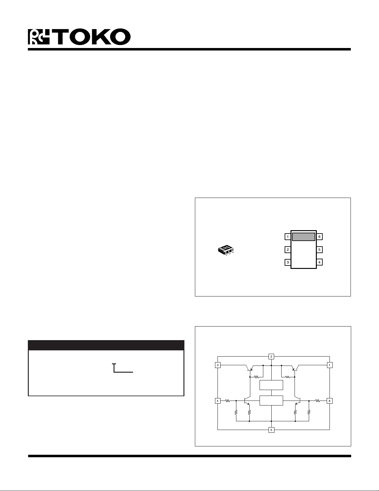
TK70001
OUTPUT 1
INPUT
OUTPUT 2
CONT 1
GND
CONT 2
The TK70001 is available in a miniature SOT-26 surface
mount package. When mounted as recommended, this
package is capable of dissipating up to 350 mW.
ORDERING INFORMATION
TK70001MCB
Tape/Reel Code
TAPE/REEL CODE
B: Tape Left
OUTPUT 2
CONT 2
BLOCK DIAGRAM
INPUT
THERMAL
PROTECTION
SW
CIRCUIT
GND
OUTPUT 1
CONT 1
January 1999 TOKO, Inc. Page 1
Page 2
TK70001
ABSOLUTE MAXIMUM RATINGS
Supply Voltage ......................................................... 14 V
Output Current .................................................... 130 mA
Power Dissipation (Note 1) ................................ 350 mW
Storage Temperature Range ................... -55 to +150 °C
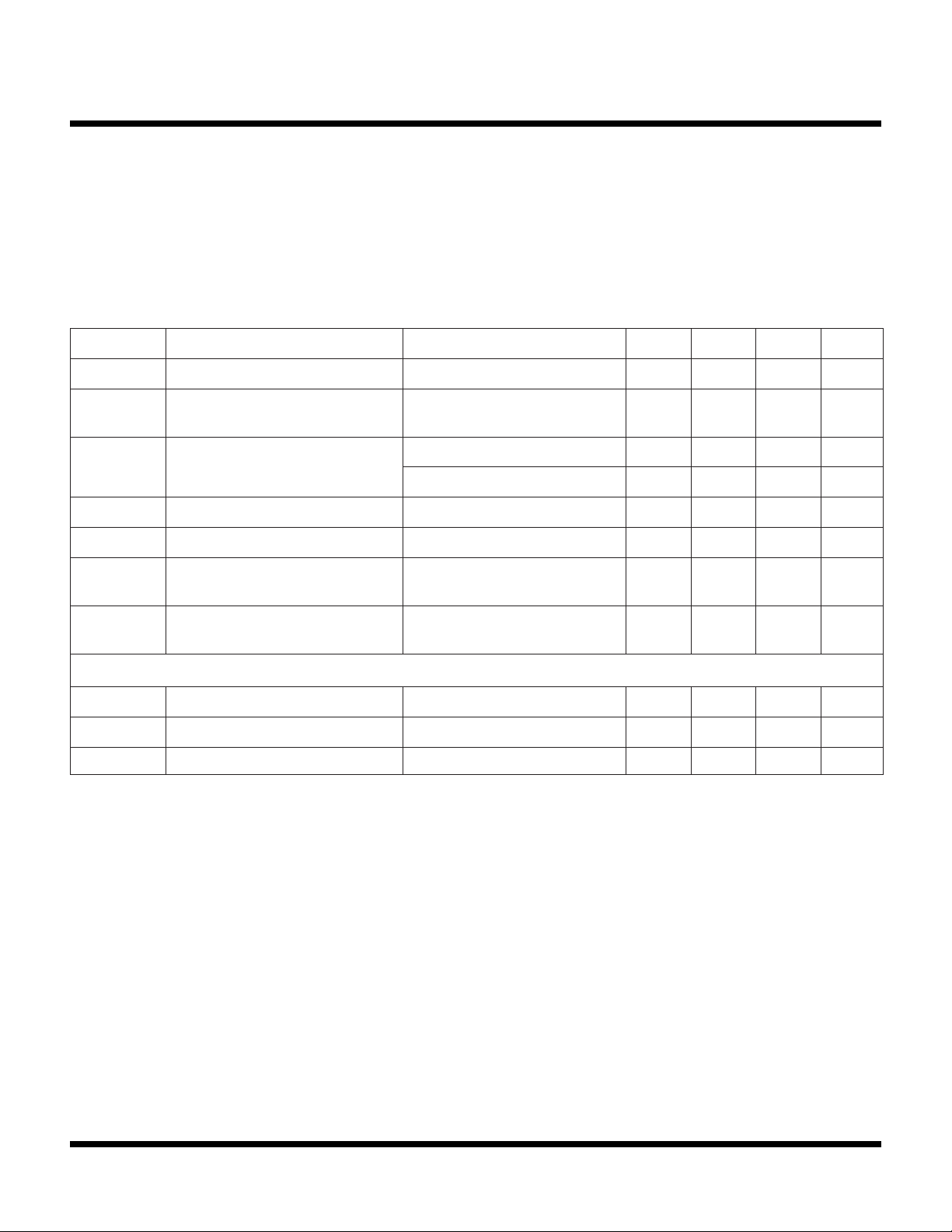
TK70001 ELECTRICAL CHARACTERISTICS
Test conditions: T
LOBMYSRETEMARAPSNOITIDNOCTSETNIMPYTXAMSTINU
= 25 °C, V
A
= 2.5 V, unless otherwise specified.
IN
Operating Temperature Range ...................-30 to +80 °C
Operating Voltage Range............................... 1.6 to 12 V
Junction Temperature .......................................... 150 °C
Lead Soldering Temperature (10 s) ..................... 235 °C
I
Q
I
I
I
V
∆V
I
YBTS
TUO
DNG
PORD
D
VER
tnerruCtnecseiuQI
tnerruCybdnatS
tnerruCtuptuO
)3etoN(tnerruCdnuorGI
egatloVtuoporDI
slennahCneewteBecnalaB
tnerruCsaiBesreveR
TUO
V
NI
V
TNOC
V
PORD
V
PORD
TUO
TUO
V
PORD
I
TUO
V
NI
V
TNOC
I,Am0=
TNOC
Aµ05=6.02.1Am
,FFOtuptuO,V8=
V0=
I,V5.0=
TNOC
I,V5.0=
TNOC
I,Am05=
TNOC
I,Am05=
TNOC
Aµ05=06001Am
Aµ001=08031Am
Aµ05=5.35.5Am
Aµ05=71.053.0V
,ecnereffid
I,Am05=
TNOC
V,V0=
VER
Aµ05=
,V8=
FFOtuptuO,V0=
1.0001An
05Vm
20.005An
LANIMRETLORTNOCFFO/NO
I
TNOC
V
V
Note 1: Power dissipation is 350 mW when mounted as recommended. Derate at 2.8 mW/°C for operation above 25°C. Power dissipation is
Note 2: By grounding this terminal, the operation completely stops and the input current decreases to a pA level.
Note 3: Ground current is defined as IIN - I
Gen. Note: Parameters with min. or max. values are 100% tested.
Gen. Note: Exceeding “Absolute Maximum Ratings” can damage the device.
)NO(TNOC
)FFO(TNOC
150 mW in Free Air. Derate at 1.2 mW/°C for operation above 25 °C.
tnerruClanimreTlortnoCV
TNOC
I,V6.1=
TUO
Am05=0559041Aµ
)NO(egatloVlortnoCNOtuptuO0.1V
)FFO(egatloVlortnoC)2etoN(FFOtuptuO2.0V
, excluding control terminal current. Refer to “Definition of Terms.”
OUT
Page 2 January 1999 TOKO, Inc.
Page 3
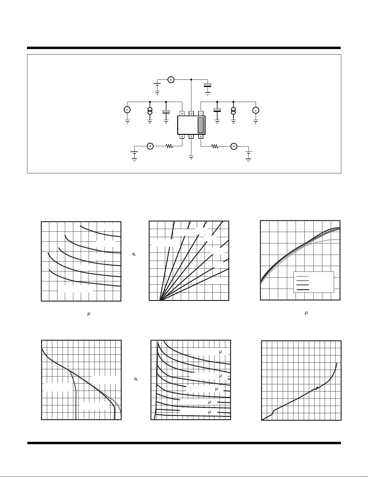
TEST CIRCUIT
INPUT
V
OUT 2
V
CONT 2
V
I
CONT 2
IN
I
OUT 2
C
L 2
R
OUTPUT 2
= 0.1 µF
CONT 2
I
IN
OUTPUT 1
C
CONT 1CONT 2
R
C
IN
1 µF
= 0.1 µF
L 1
CONT 1
I
CONT 1
I
OUT 1
V
CONT 1
V
OUT 1
TYPICAL PERFORMANCE CHARACTERISTICS
TK70001
DROPOUT VOLTAGE
CONTROL CURRENT
400
300
(mV)
200
DROP
V
75 mA
50 mA
100
I
= 25 mA
OUT
0
0 50 100
I
(
CONT
A)
DROPOUT VOLTAGE
OUTPUT CURRENT
0
100
(mV)
200
DROP
300
V
400
V
= 1 V
IN
V
IN
V
= 2.5 V
0 50 100 150
I
(mA)
OUT
VS.
125 mA
100 mA
VS.
= 5.0 V
IN
CONTROL CURRENT VS.
CONTROL VOLTAGE
100
20K
80
60
( A)
40
CONT
I
R
CONT
10K
= 0
20
0
0 1 2 3 4 5
V
(V)
CONT
QUIESCENT CURRENT VS.
INPUT VOLTAGE
500
( A)
250
Q
I
0
0 5 10 15
I
I
CONT
I
CONT
V
IN
I
CONT
I
CONT
CONT
= 20 A
= 10 A
(V)
30K
50K
75K
100K
= 50 A
= 40 A
= 30 A
MAX OUTPUT CURRENT VS.
CONTROL CURRENT
140
100
(mA)
60
OUT
I
20
V
VIN = 3.0 V
VIN = 4.5 V
VIN = 6.0 V
10 20 30 40 50
I
(
CONT
A)
REVERSE CURRENT
REVERSE VOLTAGE
2
(nA)
1
REV
I
0
0 5 10 15
V
(V)
REV
IN
= 1.5 V
VS.
January 1999 TOKO, Inc. Page 3
Page 4
TK70001
I
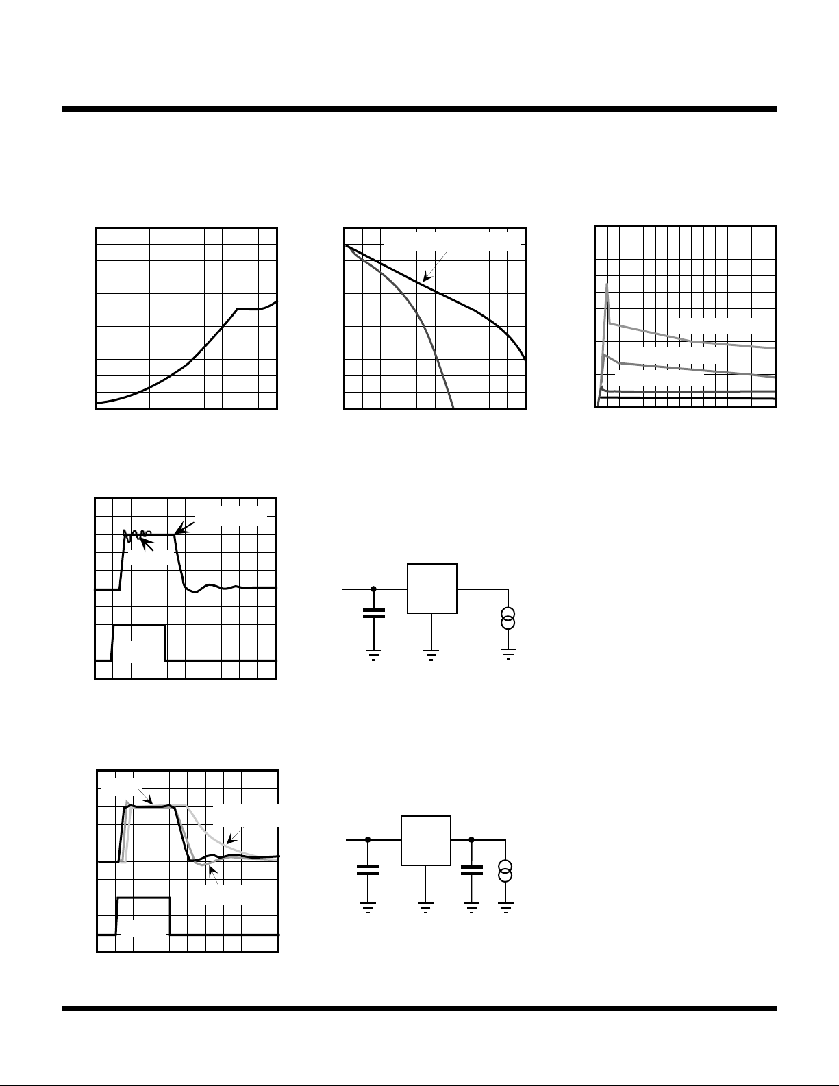
TYPICAL PERFORMANCE CHARACTERISTICS (CONT.)
GROUND CURRENT VS.
OUTPUT CURRENT
10
5
GND (mA)
I
0
0 50 100
I
(mA)
OUT
ON/OFF RESPONSE
C
IN = 0.1 µF
C
IN = 0
DROPOUT VOLTAGE
OUTPUT CURRENT
0
AT 2 CIRCUIT PARALLEL
-100
(mV)
-200
DROP
-300
V
-400
0 100 200
I
OUT (mA)
V
IN
I
OUT
VS.
= 30 mA
QUIESCENT CURRENT
INPUT VOLTAGE
5.0
I
CONT
= 50 µA
I
CONT
= 100 µA
V
IN (V)
2.5
Q (mA)
I
CONT
0
0 5 10 15
VS.
= 150 µA
C
IN
V
CONT
CIN must be over 0.1 µF
0 1 2 3 4
TIME (µs)
ON/OFF RESPONSE
C
L = 0
C
L = 0.01 µF
V
IN
C
L = 0.001 µF
V
CONT
0 1 2 3 4
TIME (µs)
1 µF
I
= 30 mA
OUT
C
L
Page 4 January 1999 TOKO, Inc.
Page 5
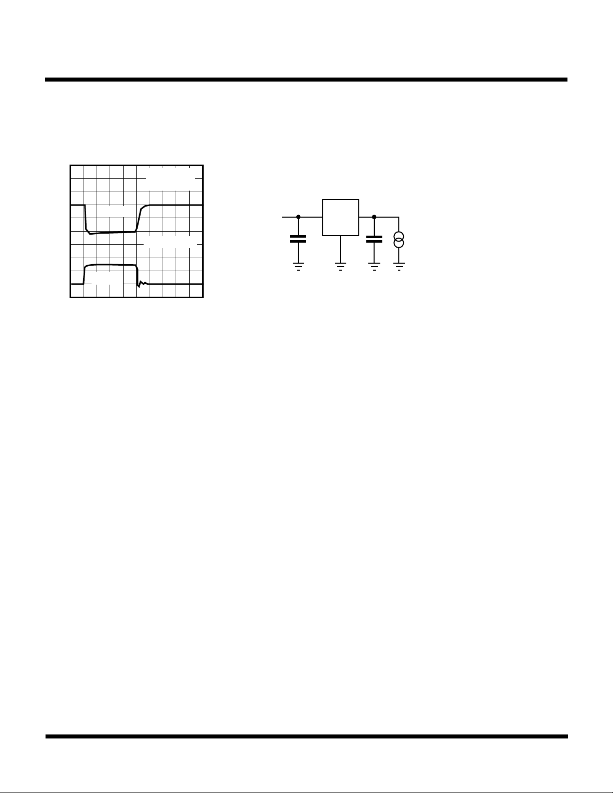
30 mA
TYPICAL PERFORMANCE CHARACTERISTICS (CONT.)
LOAD RESPONSE
V
OUT
I
0
OUT
0 10 20 30 40
TIME (µs)
C
IN = 1 µF
50 mV/ DIV
C
L = 0.1 µF
TK70001
I
= 0 to 30 mA
V
IN
1 µF
OUT
C
L
January 1999 TOKO, Inc. Page 5
Page 6

TK70001
DEFINITION AND EXPLANATION OF TECHNICAL TERMS
DROPOUT VOLTAGE (V
DROP
)
The output voltage decreases with the increase of output
current. It is dependent upon the load current and the
junction temperature. The dropout voltage is the difference
between the input voltage and the output voltage. The
measurement current is I
= 50 mA. (I
OUT
CONT
= 50 µA,
VIN = 2.5 V).
OUTPUT CURRENT (I
OUT
)
The rated output current is specified under the condition
where the output voltage drops 0.5 V below the no load
value. The input voltage is set to 2.5 V, and the current is
pulsed to minimize temperature effects.
QUIESCENT CURRENT (IQ)
The quiescent current is the current which flows through
the ground terminal under no load conditions (I
OUT
= 0 mA)
with VIN = 2.5 V and excludes the control pin current.
STANDBY CURRENT (I
STBY
)
Standby current is the current which flows into the solid
state switch when the output is turned off by the control
function (V
= 0 V). It is measured with VIN = 8 V.
CONT
ON/OFF CONTROL CURRENT
The characteristics of TK70001 change by the value of
control current. Please refer to the electrical characteristics
graphs on the data sheet and determine the optimum
value. The standard measurement condition is
I
= 50 µA. (The application is max. I
CONT
= 200 µA). In
CONT
the condition where there is very little output current,
connect the resistor R
to the control terminal (please
CONT
consider the reduction of the terminal voltage, the resistance
value, etc.). This current can be lowered.
THERMAL SENSOR
The thermal sensor protects the device in the event that
the junction temperature exceeds the safe value (Tj =
150 °C). This temperature rise can be caused by external
heat, excessive power dissipation caused by large input to
output voltage drop, or excessive output current. The
switch will shut off when the temperature exceeds the safe
value. As the junction temperature decreases, the switch
will begin to operate again. Under sustained fault conditions,
the switch output will cycle as the device turns off, and then
resets. Damage may occur to the device under extreme
fault conditions.
PACKAGE POWER DISSIPATION (PD)
GROUND CURRENT (I
GND
)
This is the power dissipation level at which the thermal
sensor is activated. The IC contains an internal thermal
Ground current is the current which flows through the
ground pin(s). It is defined as IIN - I
, excluding control
OUT
current.
sensor which monitors the junction temperature. When the
junction temperature exceeds the monitor threshold of
150 °C, the IC is shut down. The junction temperature
rises as the difference between the input power (VIN x IIN)
ON/OFF CONTROL
and the output power (V
OUT
x I
) increases. The rate of
OUT
temperature rise is greatly affected by the mounting pad
High is “on” (referenced to ground). The input current is at
the pA level by connecting the control terminal to ground.
configuration on the PCB, the board material, and the
ambient temperature. When the IC mounting has good
thermal conductivity, the junction temperature will be low
REVERSE VOLTAGE PROTECTION
even if the power dissipation is great. When mounted on
the recommended mounting pad, the power dissipation of
Reverse voltage protection prevents damage due to the
output voltage being higher than the input voltage. This
fault condition can occur when the output capacitor remains
charged and the input is reduced to zero, or when an
external voltage higher than the input voltage is applied to
the output side.
the SOT-26 is increased to 350 mW. For operation at
ambient temperatures over 25 °C, the power dissipation of
the SOT-26 device should be derated at 2.8 mW/°C. To
determine the power dissipation for shutdown when
mounted, attach the device on the actual PCB and
deliberately increase the output current (or raise the input
voltage) until the thermal protection circuit is activated.
Calculate the power dissipation of the device by subtracting
the output power from the input power. These
Page 6 January 1999 TOKO, Inc.
Page 7
TK70001
+
GND
INPUT
+
+
PCB: CLASS EPOXY T=0.8 mM
OUTPUT 2
OUTPUT 1
CONT 1
CONT 2
DEFINITION AND EXPLANATION OF TECHNICAL TERMS (CONT.)
measurements should allow for the ambient temperature
of the PCB. The value obtained from PD /(150 °C - TA) is the
derating factor. The PCB mounting pad should provide
maximum thermal conductivity in order to maintain low
device temperatures. As a general rule, the lower the
temperature, the better the reliability of the device. The
thermal resistance when mounted is expressed as follows:
Tj = 0jA x PD + T
A
For Toko ICs, the internal limit for junction temperature is
150 °C. If the ambient temperature (TA) is 25 °C, then:
150 °C = 0jA x PD + 25 °C
0jA = 125 °C/ P
D
PD is the value when the thermal sensor is activated. A
simple way to determine PD is to calculate VIN x IIN when
the output side is shorted. Input current gradually falls as
temperature rises. You should use the value when thermal
equilibrium is reached.
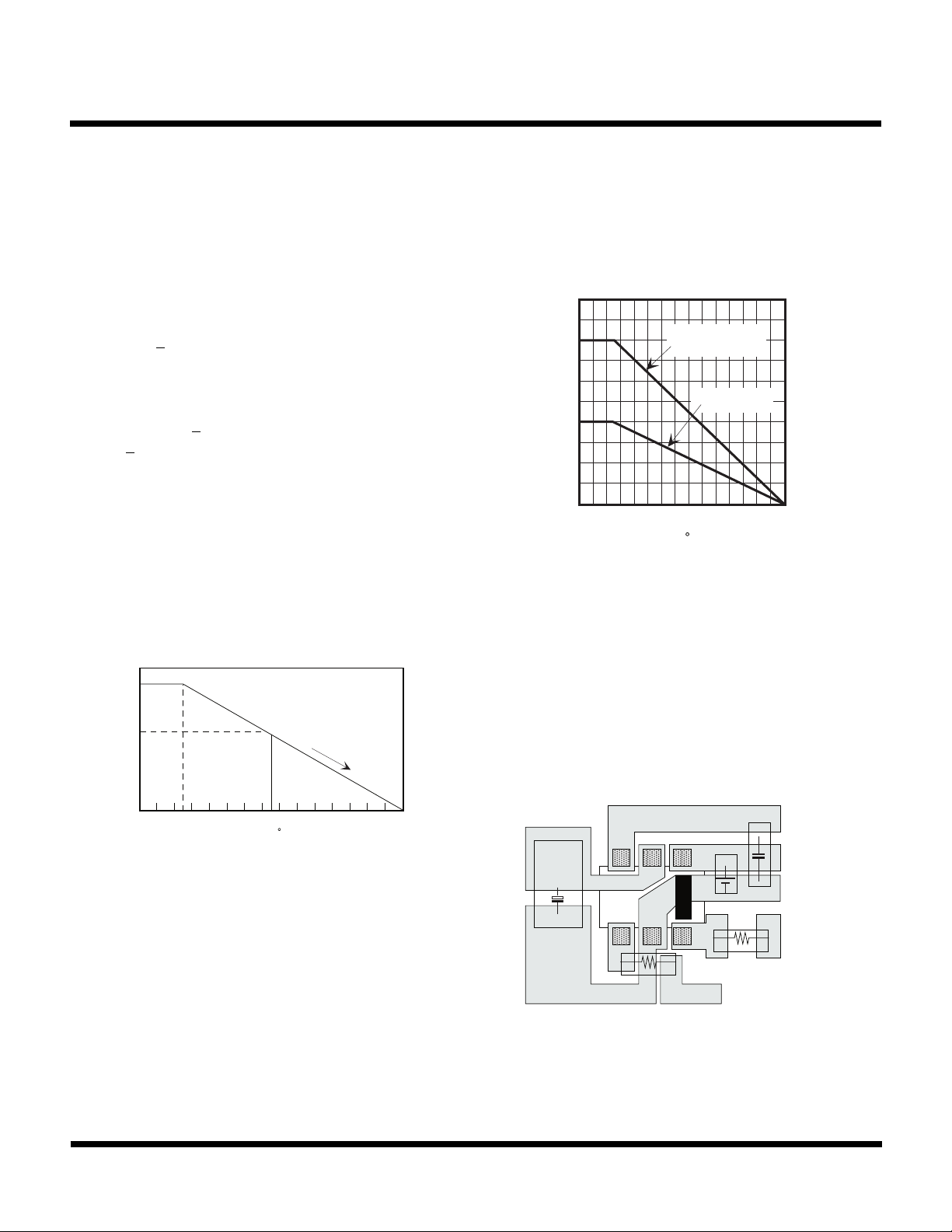
The range of usable currents can also be found from the
graph below.
(mW)
P
D
D
PD
3
6
4
5
The maximum operating current is:
I
= (D
OUT
450
350
250
(mW)
D
150
P
50
0
0 50 100 150
PD
/ (V
IN(MAX) - VOUT
MOUNTED AS
SHOWN
FREE AIR
TA (
C)
)
SOT-26 POWER DISSIPATION
APPLICATION INFORMATION
BOARD LAYOUT
The copper pattern should be as large as possible.
25 50 75 150
TA (
C)
Procedure:
1) Find P
D
2) PD1 is taken to be PD x (~ 0.8 - 0.9)
3) Plot PD1 against 25 °C
4) Connect P
to the point corresponding to the 150 °C
D1
with a straight line.
5) In design, take a vertical line from the maximum
operating temperature (e.g., 75 °C) to the derating
curve.
6) Read off the value of PD against the point at which the
vertical line intersects the derating curve. This is taken
as the maximum power dissipation, DPD.
SOT-26 BOARD LAYOUT
January 1999 TOKO, Inc. Page 7
Page 8
TK70001
)
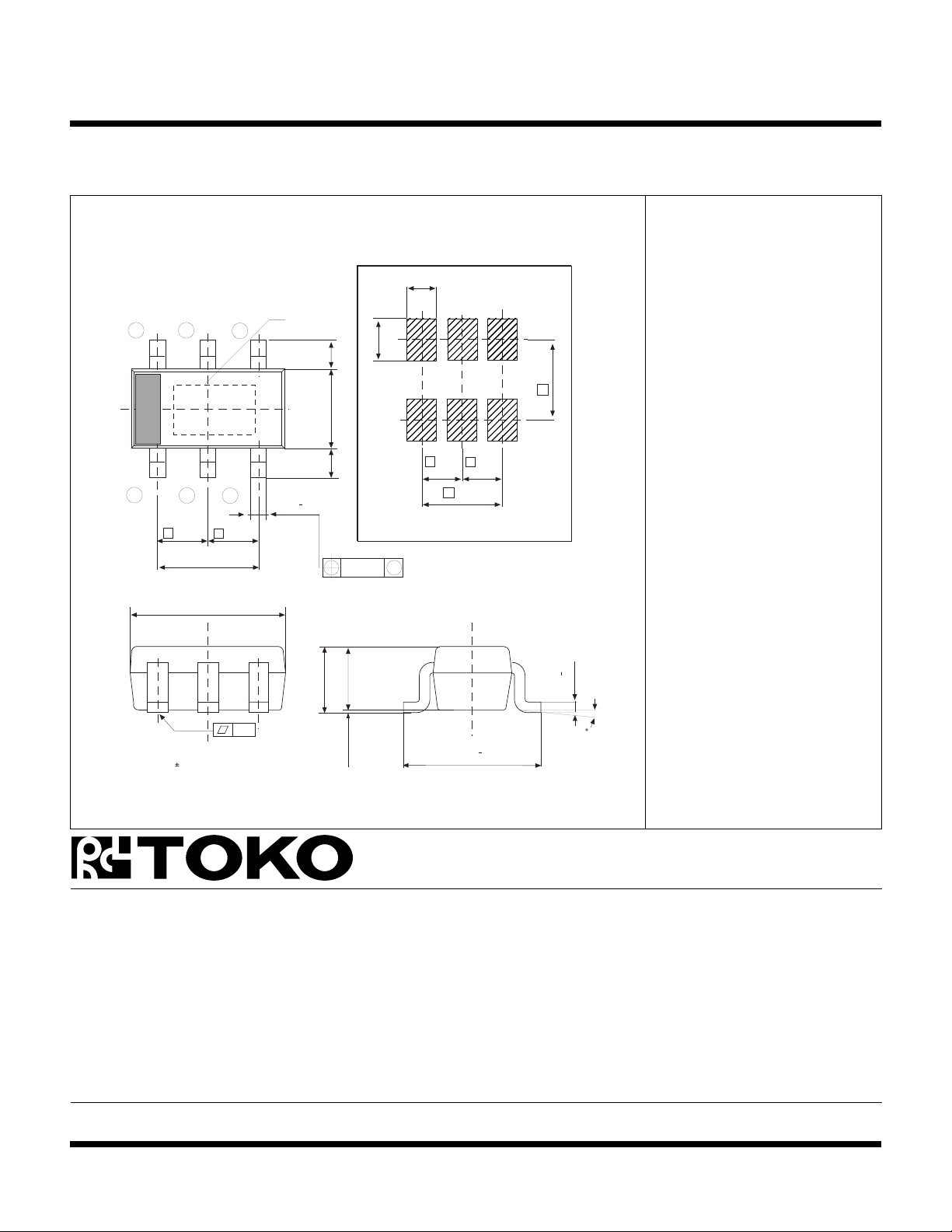
PACKAGE OUTLINE
SOT-26 (SOT-23-6)
6
1
5
2
e
(1.9)
4
3
0.950.95
e
2.9
Marking
0.3
Marking Information
0.7
1.0
(0.6)
2.4
1
e
1.6
e
(0.6)
+
0.1
Recommended Mount Pad
M
0.1
1.1
1.4 max
0.95
e
0.95
e
1.90
0.1
+
0.15
Marking
TK70001 01S
0.1
Dimensions are shown in millimeters
Tolerance: x.x = 0.2 mm (unless otherwise specified
0 ~ 0.1
+
0.3
2.8
0-13
Toko America, Inc. Headquarters
1250 Feehanville Drive, Mount Prospect, Illinois 60056
Tel: (847) 297-0070 Fax: (847) 699-7864
TOKO AMERICA REGIONAL OFFICES
Midwest Regional Office
Toko America, Inc.
1250 Feehanville Drive
Mount Prospect, IL 60056
Tel: (847) 297-0070
Fax: (847) 699-7864
Western Regional Office
Toko America, Inc.
2480 North First Street , Suite 260
San Jose, CA 95131
Tel: (408) 432-8281
Fax: (408) 943-9790
Eastern Regional Office
Toko America, Inc.
107 Mill Plain Road
Danbury, CT 06811
Tel: (203) 748-6871
Fax: (203) 797-1223
Semiconductor Technical Support
Toko Design Center
4755 Forge Road
Colorado Springs, CO 80907
Tel: (719) 528-2200
Fax: (719) 528-2375
Visit our Internet site at http://www.tokoam.com
The information furnished by TOKO, Inc. is believed to be accurate and reliable. However, TOKO reserves the right to make changes or improvements in the design, specification or manufacture of its
products without further notice. TOKO does not assume any liability arising from the application or use of any product or circuit described herein, nor for any infringements of patents or other rights of
third parties which may result from the use of its products. No license is granted by implication or otherwise under any patent or patent rights of TOKO, Inc.
Page 8 January 1999 TOKO, Inc.
All Rights Reserved
IC-216-TK70001
0798O0.0K
Printed in the USA© 1999 Toko, Inc.
 Loading...