

Page 1
TIL300, TIL300A
PRECISION LINEAR OPTOCOUPLER
TAOS018 – AUGUST 1999
ac or dc Signal Coupling
Wide Bandwidth ...>200 kHz
High Transfer-Gain Stability...±0.005%/°C
3500 V Peak Isolation
Typical Applications
– Power-Supply Feedback
– Medical-Sensor Isolation
DCS OR P PACKAGE
(TOP VIEW)
LEDK
LEDA
PDK1
PDA1
NC – No internal connection
1
2
3
4
8
7
6
5
NC
NC
PDK2
PDA2
– Opto Direct-Access Arrangement (DAA)
– Isolated Process-Control Transducers
Description
The TIL300 precision linear optocoupler consists of an infrared LED irradiating an isolated feedback photodiode
and an output photodiode in a bifurcated arrangement. The feedback photodiode captures a percentage of the
flux of the LED that can be used to generate a control signal to regulate the LED drive current. This technique
is used to compensate for the nonlinear time and temperature characteristics of the LED. The output-side
photodiode then produces an output signal that is linearly proportional to the servo-optical flux emitted from the
LED.
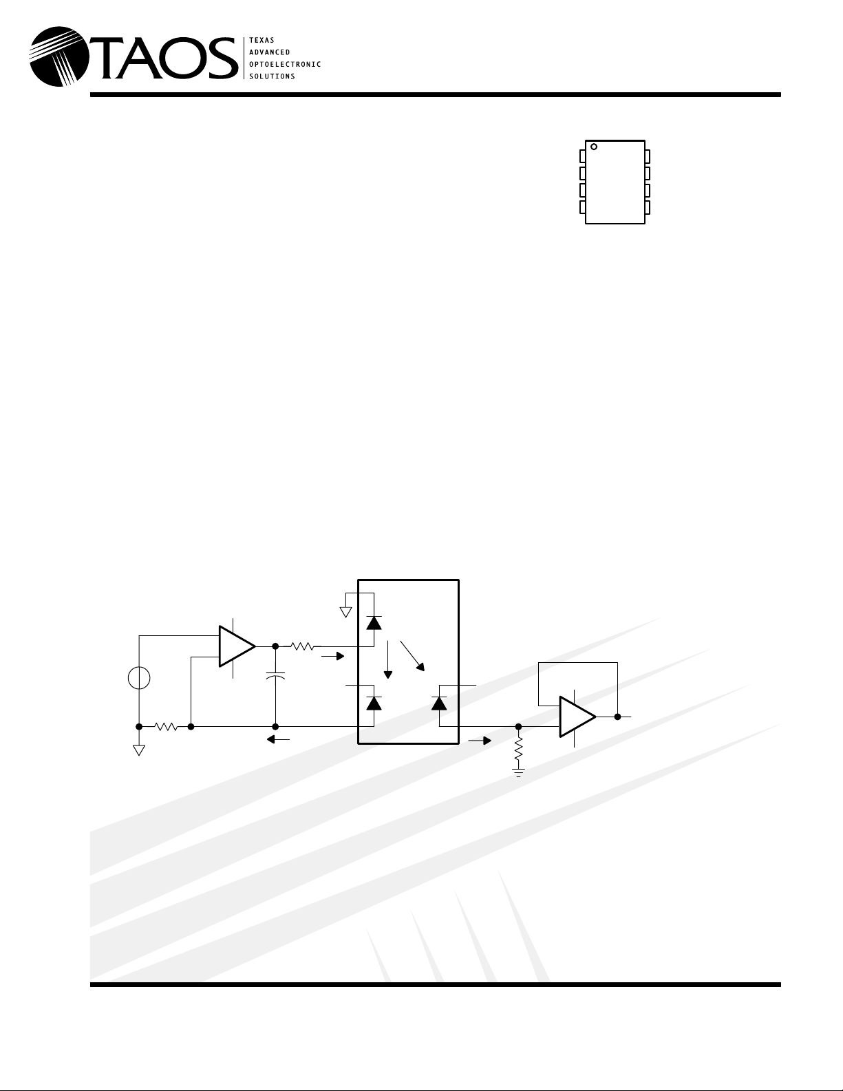
A typical application circuit (shown in Figure 1) uses an operational amplifier as the input to drive the LED. The
feedback photodiode sources current through R1, which is connected to the inverting input of the input
operational amplifier. The photocurrent I
magnitude of the current is directly proportional to the LED current through the feedback transfer gain
K1(VI/R1 = K1 × IF). The operational amplifier supplies LED current to produce sufficient photocurrent to keep
the node voltage V
equal to node voltage V
b
assumes a magnitude that satisfies the relationship IP1 = V
P1
a.
/R1. The
I
TIL300
1
1V
CC+
V
a
+
V
b
1V
_
CC–
+
V
I
–
R1
P
NOTES: A. K1 is servo current gain, the ratio of the feedback servo photodiode current (IP1) to the input LED current (IF), i.e. K1 = IP1/I
B. K2 is forward gain, the ratio of the output photodiode current (IP2) to the input LED current (IF), i.e. K2 = IP2/IF.
C. K3 is transfer gain, the ratio of the forward gain to the servo gain, i.e. K3 = K2/K1.
R3
I
P1
I
1V
P
2
F
3
CC+
4
K1
K2
R2
2V
2V
CC+
–
+
CC–
VO = K3(R2/R1) V
I
6
2V
CC+
5
I
P2
Figure 1. Typical Application Circuit
The output photodiode is connected to a noninverting voltage follower; R2 is used to develop a voltage from
the photodiode current. The output of the amplifier is VO = K2IFR2. Overall transfer gain VO/VI becomes
VO/VI = (K2IFR2/K1IFR1). Factoring out the LED forward current IF and remembering that K2/K1 = K3, the
overall transfer gain becomes VO/VI = K3R2/R1. The overall transfer gain, therefore, is shown to be
independent of the LED current.
F.
www.taosinc.com
Texas Advanced Optoelectronic Solutions Inc.
800 Jupiter Road, Suite 205 Plano, TX 75074 (972) 673-0759
Copyright 2000, TAOS Inc.
1
Page 2

TIL300, TIL300A
PRECISION LINEAR OPTOCOUPLER
TAOS018 – AUGUST 1999
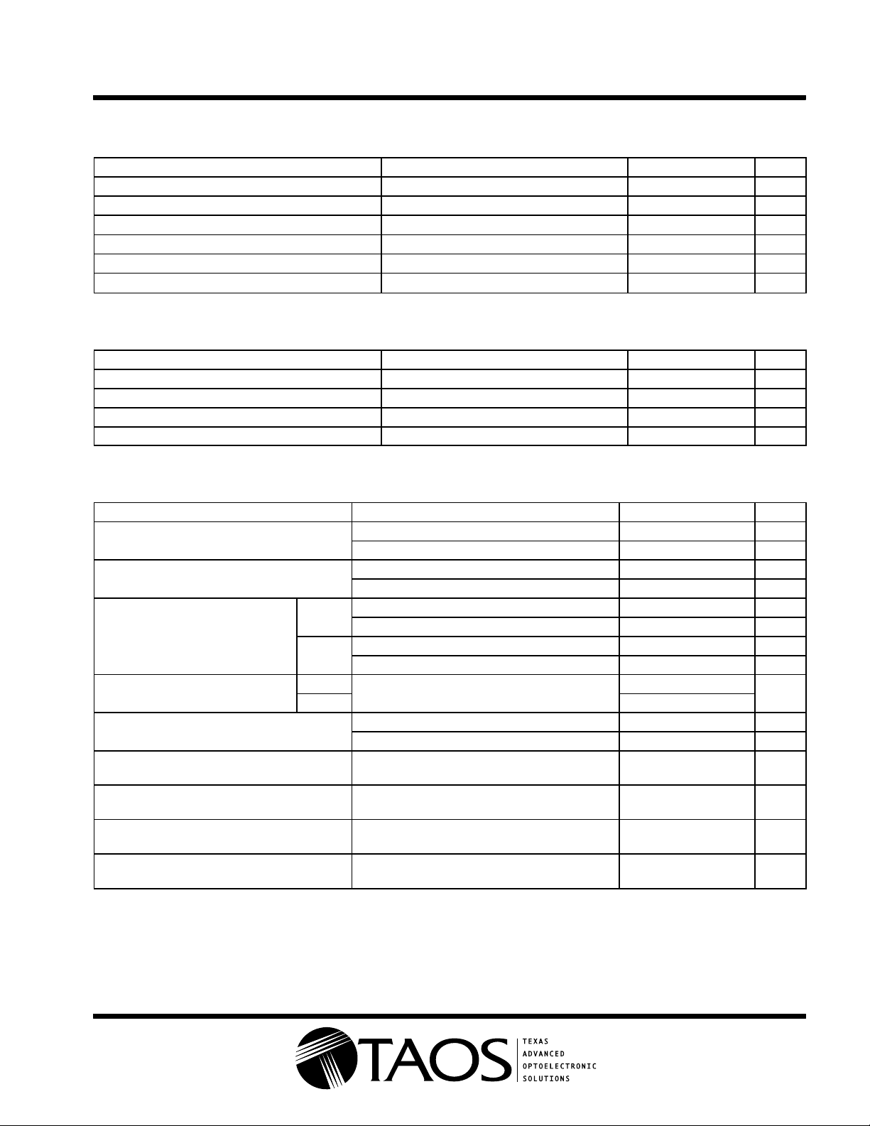
Terminal Functions
TERMINAL
NAME NO.
LEDK 1 LED cathode
LEDA 2 LED anode
PDK1 3 Photodiode 1 cathode
PDA1 4 Photodiode 1 anode
PDA2 5 Photodiode 2 anode
PDK2 6 Photodiode 2 cathode
NC 7 No internal connection
NC 8 No internal connection
DESCRIPTION
Absolute Maximum Ratings over operating free-air temperature range (unless otherwise noted)
Emitter
Continuous total power dissipation (see Note 1) 160 mW. . . . . . . . . . . . . . . . . . . . . . . . . . . . . . . . . . . . . . . . . . . .
Input LED forward current, IF 60 mA. . . . . . . . . . . . . . . . . . . . . . . . . . . . . . . . . . . . . . . . . . . . . . . . . . . . . . . . . . . . .
Surge current with pulse duration < 10 µs 250 mA. . . . . . . . . . . . . . . . . . . . . . . . . . . . . . . . . . . . . . . . . . . . . . . . . .
Reverse voltage, VR 5 V. . . . . . . . . . . . . . . . . . . . . . . . . . . . . . . . . . . . . . . . . . . . . . . . . . . . . . . . . . . . . . . . . . . . . . . .
Reverse current, IR 10 µA. . . . . . . . . . . . . . . . . . . . . . . . . . . . . . . . . . . . . . . . . . . . . . . . . . . . . . . . . . . . . . . . . . . . . . .
Detector
Continuous total power dissipation (see Note 2) 50 mW. . . . . . . . . . . . . . . . . . . . . . . . . . . . . . . . . . . . . . . . . . . . .
Reverse voltage, VR 50 V. . . . . . . . . . . . . . . . . . . . . . . . . . . . . . . . . . . . . . . . . . . . . . . . . . . . . . . . . . . . . . . . . . . . . . .
†
Coupler
Continuous total power dissipation (see Note 3) 210 mW. . . . . . . . . . . . . . . . . . . . . . . . . . . . . . . . . . . . . . . . . . . .
Storage temperature range, T
–55°C to 150°C. . . . . . . . . . . . . . . . . . . . . . . . . . . . . . . . . . . . . . . . . . . . . . . . . . .
stg
Operating free-air temperature range, TA –55°C to 100°C. . . . . . . . . . . . . . . . . . . . . . . . . . . . . . . . . . . . . . . . . . .
Input-to-output voltage 3535 Vpeak. . . . . . . . . . . . . . . . . . . . . . . . . . . . . . . . . . . . . . . . . . . . . . . . . . . . . . . . . . . . . .
Lead temperature 1,6 mm (1/16 inch) from case for 10 seconds 260°C. . . . . . . . . . . . . . . . . . . . . . . . . . . . . . .
†
Stresses beyond those listed under “absolute maximum ratings” may cause permanent damage to the device. These are stress ratings only, and
functional operation of the device at these conditions is not implied. Exposure to absolute-maximum-rated conditions for extended periods may
affect device reliability.
NOTES: 1. Derate linearly from 25°C at a rate of 2.66 mW/°C.
2. Derate linearly from 25°C at a rate of 0.66 mW/°C.
3. Derate linearly from 25°C at a rate of 3.33 mW/°C.
2
www.taosinc.com
Page 3
TIL300, TIL300A
PRECISION LINEAR OPTOCOUPLER
TAOS018 – AUGUST 1999
Electrical Characteristics at T
= 25°C (unless otherwise noted)
A
Emitter
PARAMETER TEST CONDITIONS MIN TYP MAX UNIT
V
F
I
R
t
r
t
f
C
j
LED forward voltage I
Temperature coefficient of V
F
Reverse current V
Rise time I
Fall time I
Junction capacitance V
= 10 mA 1.25 1.50 V
F
–2.2 mV/°C
= 5 V 10 µA
R
= 10 mA, ∆IF = 2 mA 1 µs
F
= 10 mA, ∆IF = 2 mA 1 µs
F
= 0, f = 1 MHz 15 pF
F
Detector
PARAMETER TEST CONDITIONS MIN TYP MAX UNIT
†
I
DK
I
OS
C
j
Dark current V
Open-circuit voltage I
Short-circuit current limit I
Junction capacitance V
= -15 V, IF = 0 25 nA
R
= 10 mA 0.5 V
F
= 10 mA 80 µA
F
= 0, f = 1 MHz 12 pF
F
Coupler , detector bias voltage, VR = –15 V
PARAMETER TEST CONDITIONS MIN TYP MAX UNIT
†
Servo-current gain
K1
‡
Forward current gain
K2
TIL300
§
K3
Transfer gain
TIL300A
Gain temperature coefficient
¶
Transfer gain linearity
∆K3
K1/K2
K3
BW Bandwidth
t
Rise time
r
t
Fall time
f
#
V
Peak isolation voltage
iso
†
Servo-current gain (K1) is the ratio of the feedback photodiode current (IP1) to the input LED current (IF) current (IF), i.e. K1 = IP1/IF.
‡
Forward gain (K2 is the ratio of the output photodiode current (IP2) to the input LED current (IF), i.e. K2 = IP2/IF.
§
Transfer gain (K3) is the ratio of the forward gain to the servo-current gain, i.e. K3 = K2/K1.
¶
Transfer gain linearity (∆K3) is the percent deviation of the transfer gain K3 as a function of LED input current (IF) or the package temperature.
#
This symbol is not currently listed within EIA or JEDEC standards for semiconductor symbology.
IF = 1 mA 0.3% 0.7% 1.5%
IF = 10 mA 0.5% 1.25% 2%
IF = 1 mA 0.3% 0.7% 1.5%
IF = 10 mA 0.5% 1.25% 2%
IF = 1 mA 0.75 1 1.25
IF = 10 mA 0.75 1 1.25
IF = 1 mA 0.9 1 1.10
IF = 10 mA 0.9 1 1.10
IF = 10 mA
I
= 1 to 10 mA ±0.25%
F
I
= 1 to 10 mA, T
F
I
= 10 mA,
F
I
F(MODULATION)
I
= 10 mA,
F
I
F(MODULATION)
I
= 10 mA,
F
I
F(MODULATION)
I
= 10 µA, f = 60 Hz,
IO
= ±2 mA
= ±2 mA
= ±2 mA
time = 1 minute
= 0 to 75°C ±0.5%
A
R
= 1 kΩ,
L
R
= 1 kΩ,
L
R
= 1 kΩ,
L
3535 V
–0.5
±0.005
200 kHz
1.75 µs
1.75 µs
%/°C
www.taosinc.com
3
Page 4

TIL300, TIL300A
PRECISION LINEAR OPTOCOUPLER
TAOS018 – AUGUST 1999
TYPICAL CHARACTERISTICS
Table of Graphs
FIGURE
I
F
I
p1
I
p1
K1 Normalized Servo Current Gain vs LED Forward Current and Temperature 8
K3 Normalized Transfer Gain vs LED Forward Current 9
A
O
LED Forward Current
Servo Photodiode Current
Normalized Servo Photodiode Current vs LED Forward Current and Temperature
Output Current Amplitude vs Frequency 10
vs LED Forward Voltage 2
vs LED Forward Voltage 3
vs LED Forward Current and Temperature 4
vs LED Forward Current and Temperature 5
6
7
4
www.taosinc.com
Page 5

PRECISION LINEAR OPTOCOUPLER
TYPICAL CHARACTERISTICS
TIL300, TIL300A
TAOS018 – AUGUST 1999
LED FORWARD CURRENT
vs
LED FORWARD VOLTAGE
30
TA = 25°C
25
20
15
10
– LED Forward Current – mA
F
I
5
0
1 1.1 1.2 1.3
VF – LED Forward Voltage – V
1.4 1.5 1.6
Figure 2
SERVO PHOTODIODE CURRENT
vs
LED FORWARD CURRENT AND TEMPERATURE
500
450
400
350
300
250
200
150
Servo Photodiode Current –
–Aµ
100
p1
I
50
0
0.1 1
IF – LED Forward Current – mA
TA = 0°C
TA = 25°C
TA = 50°C
TA = 75°C
10 100
LED FORWARD CURRENT
vs
LED FORWARD VOLTAGE
100
TA = 25°C
10
1
– LED Forward Current – mA
F
I
0.1
1 1.1 1.2 1.3 1.4
VF – LED Forward Voltage – V
Figure 3
SERVO PHOTODIODE CURRENT
vs
LED FORWARD CURRENT AND TEMPERATURE
1000
700
400
TA = 50°C
T
= 75°C
A
TA = 25°C
200
100
70
40
20
10
7
Servo Photodiode Current –I
–Aµ
4
p1
2
1
0.1 0.2 0.4 0.7 1 2 4
IF – LED Forward Current – mA
TA = 0°C
10 40 701000
720
1.5
1.6
www.taosinc.com
Figure 4 Figure 5
5
Page 6

TIL300, TIL300A
PRECISION LINEAR OPTOCOUPLER
TAOS018 – AUGUST 1999
TYPICAL CHARACTERISTICS
NORMALIZED SERVO PHOTODIODE CURRENT
vs
LED FORWARD CURRENT AND TEMPERATURE
4
Normalized at
IF = 10 mA
3.5
TA = 25°C
VR = –15 V
3
2.5
2
1.5
1
Normalized Servo Photodiode CurrentI
0.5
–
p1
0
0 5 10 15 20
TA = 75°C
IF – LED Forward Current – mA
TA = 25°C
TA = 50°C
TA = 0°C
Figure 6
NORMALIZED SERVO CURRENT GAIN
vs
LED FORWARD CURRENT AND TEMPERATURE
1.4
Normalized at
IF = 10 mA
1.2
TA = 25°C
1
TA = 25°C
TA = 50°C
TA = 75°C
TA = 0°C
25 30
NORMALIZED SERVO PHOTODIODE CURRENT
vs
LED FORWARD CURRENT AND TEMPERATURE
10
Normalized at
IF = 10 mA
TA = 25°C
VR = –15 V
1
0.1
Normalized Servo Photodiode CurrentI
–
p1
0.01
0.1
IF – LED Forward Current – mA
TA = 25°C
TA = 50°C
TA = 75°C
1
TA = 0°C
10 100
Figure 7
NORMALIZED TRANSFER GAIN
vs
LED FORWARD CURRENT
1.3
Normalized at
IF = 10 mA
TA = 25°C
1.2
VR = –15 V
1.1
0.8
0.6
0.4
K1 – Normalized Servo Current Gain
0.2
0
0.1 1
IF – LED Forward Current – mA
Figure 8 Figure 9
6
10 100
1
0.9
0.8
K3 – Normalized Transfer Gain – (K2/K1)
0.7
0 5 10 15 20
IF – LED Forward Current
25 30
www.taosinc.com
Page 7

TYPICAL CHARACTERISTICS
OUTPUT CURRENT AMPLITUDE
IF = 10 mA
5
MOD = ±2 mA (peak)
VR = 15 V
0
–5
TIL300, TIL300A
PRECISION LINEAR OPTOCOUPLER
TAOS018 – AUGUST 1999
vs
FREQUENCY
RL = 1 kΩ
–10
–15
– Output Current Amplitude – dB
O
A
–20
–25
10 20 40 70 100 200
f – Frequency – kHz
RL = 10 kΩ
400 700 1000
Figure 10
www.taosinc.com
7
Page 8

TIL300, TIL300A
PRECISION LINEAR OPTOCOUPLER
TAOS018 – AUGUST 1999
MECHANICAL DATA
DCS (R-PDSO-G8) PLASTIC DUAL SMALL-OUTLINE OPTO COUPLER
0.023 (0,58)
0.013 (0,33)
0.045 (1,14)
0.035 (0,89)
0.055 (1,40)
0.035 (0,89)
8
1
0.390 (9,91)
0.370 (9,40)
0.150 (3,81) MAX
0.092 (2,34) TYP
0.055 (1,40)
0.045 (1,14)
5
4
0.260 (6,60)
0.240 (6,10)
0.100 (2,54)
0.405 (10,29)
0.385 (9,78)
0.008 (0,20) NOM
Gage Plane
0°–5°
0.010 (0,25)
0.030 (0,76) MIN
0.020 (0,51) MAX
NOTES: A. All linear dimensions are in inches(millimeters).
B. This drawing is subject to change without notice.
Seating Plane
0.004 (0,10)
4073327/B 01/98
www.taosinc.com
8
Page 9

TIL300, TIL300A
PRECISION LINEAR OPTOCOUPLER
TAOS018 – AUGUST 1999
MECHANICAL DATA
P (R-PDIP-T8) PLASTIC DUAL-IN-LINE PACKAGE
0.400 (10,60)
0.355 (9,02)
58
0.260 (6,60)
0.240 (6,10)
41
0.070 (1,78) MAX
0.020 (0,51) MIN
0.200 (5,08) MAX
0.125 (3,18) MIN
0.100 (2,54)
0.021 (0,53)
0.015 (0,38)
NOTES: A. All linear dimensions are in inches (millimeters).
B. This drawing is subject to change without notice.
C. Falls within JEDEC MS-001
0.010 (0,25)
M
0.310 (7,87)
0.290 (7,37)
Seating Plane
0°–15°
0.010 (0,25) NOM
4040082/B 03/95
www.taosinc.com
9
Page 10

TIL300, TIL300A
PRECISION LINEAR OPTOCOUPLER
TAOS018 – AUGUST 1999
PRODUCTION DATA — information in this document is current at publication date. Products conform to
specifications in accordance with the terms of Texas Advanced Optoelectronic Solutions, Inc. standard
warranty. Production processing does not necessarily include testing of all parameters.
NOTICE
Texas Advanced Optoelectronic Solutions, Inc. (TAOS) reserves the right to make changes to the products contained in this
document to improve performance or for any other purpose, or to discontinue them without notice. Customers are advised
to contact TAOS to obtain the latest product information before placing orders or designing TAOS products into systems.
TAOS assumes no responsibility for the use of any products or circuits described in this document or customer product
design, conveys no license, either expressed or implied, under any patent or other right, and makes no representation that
the circuits are free of patent infringement. TAOS further makes no claim as to the suitability of its products for any particular
purpose, nor does TAOS assume any liability arising out of the use of any product or circuit, and specifically disclaims any
and all liability, including without limitation consequential or incidental damages.
TEXAS ADVANCED OPTOELECTRONIC SOLUTIONS, INC. PRODUCTS ARE NOT DESIGNED OR INTENDED FOR
USE IN CRITICAL APPLICATIONS IN WHICH THE FAILURE OR MALFUNCTION OF THE TAOS PRODUCT MAY
RESUL T I N PERSONAL INJURY OR DEATH. USE OF TAOS PRODUCTS IN LIFE SUPPOR T SYSTEMS IS EXPRESSLY
UNAUTHORIZED AND ANY SUCH USE BY A CUSTOMER IS COMPLETELY AT THE CUSTOMER’S RISK.
10
www.taosinc.com
 Loading...