

Page 1
THDT6511D
ApplicationSpecific Discretes
A.S.D.
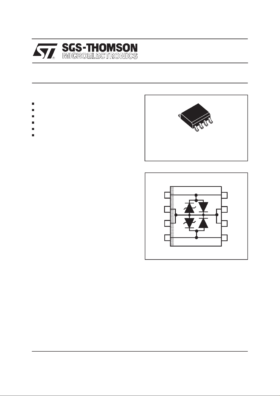
FEATURES
DUALASYMETRICALTRANSIEN TSUPPR ESSOR
PEAKPULSE CURRENT: I
HOLDINGCURRENT: 150mA min.
BREAKDOWNVOLTAGE: 65V min.
LOWDYNAMICCHARACTERISTICS
STANDCCITT K20 ANDLSSGR
DESCRIPTION
This device has been especially designed to
protectsubscriberline cardsagainst overvoltage.
Two diodes clamp positive overloads while
negativesurges are suppressedby two protection
thyristors.
Aparticularattentionhas beengiven to theinternal
wire bonding. The ”4-point” configuration ensures
a reliable protection, eliminating overvoltages
introduced by the parasitic inductances of the
wiring (Ldi/dt), especially for very fast transient
overvoltages.
= 40A, 10/100µs
PP
TRANSIENT VOLTAGE SUPPRESSOR
FOR SLIC PROTECTION
PRELIMINARY DATASHEET
SO8
SCHEMATIC DIAGRAM
TIP
GND
GND
1
2
3
TIP
8
GND
7
GND
6
COMPLIESWITHTHEFOLLOWINGSTANDAR DS:
CCITTK20 : 10/700µs 1kV
5/310µs 38A
VDE0433 : 10/700µs 2kV
5/310µs 50A
VDE0878 : 1.2/50µs 1.5kV
1/20µs 40A
I3124 :
FCCpart 68 :
BELLCORE
TR-NWT-001089: 2/10µs 2.5kV
(*)with series resistors or PTC.
February 1998 - Ed: 2
0.5/700µs 1kV
0.2/310µs 38A
2/10µs 2.5kV
2/10µs 125A (*)
2/10µs 125A (*)
10/1000µs 1kV
10/1000µs 40A (*)
RING
45
RING
1/6
Page 2
THDT6511D
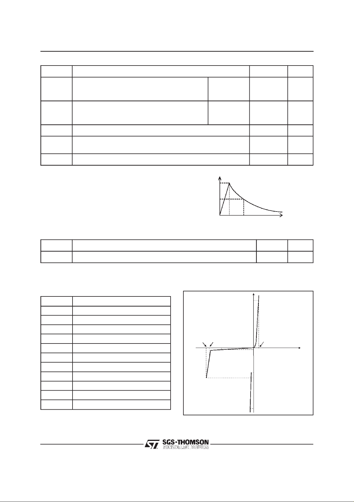
ABSOLUTE MAXIMUM RATINGS (T
amb
=25°C)
Symbol Parameter Value Unit
I
PP
I
TSM
I
TSM
T
stg
T
j
T
L
Note 1 : Pulse waveform :
Peak pulsecurrent (see note1) 10/1000µs
5/310µs
2/10µs
Non repetitivesurge peakon-statecurrent
F = 50 Hz
t = 300ms
t=1s
t=5s
40
50
125
10
3.5
1
F = 50 Hz, 60 x 1s, 2 mn betweenpulse 1 A
Storagetemperaturerange
Maximumjunctiontemperature
- 55 to+ 150
150
Maximumleadtemperaturefor solderingduring 10s 260 °C
%I
10/1000µstr=10µst
5/310µst
2/10µst
=5µst
r
=2µst
r
=1000µs
p
=310µs
p
=10µs
p
100
50
0
PP
t
rp
t
t
A
A
°C
THERMAL RESISTANCES
Symbol Parameter Value Unit
R
th (j-a)
Junctionto ambient
170 °C/W
ELECTRICAL CHARACTERISTICS
(T
=25°C)
amb
Symbol Parameter
V
RM
I
RM
V
BR
V
BO
I
H
V
F
V
FP
I
BO
I
PP
Stand-offvoltage
Leakagecurrentat stand-offvoltage
Breakdownvoltage
Breakovervoltage
Holdingcurrent
Forward voltagedrop
Peak forwardvoltage
Breakovercurrent
Peak pulsecurrent
VBO
VBR
VRM
I
IF
VF
IRM
IH
IBO
C Capacitance
αT Temperaturecoefficient
Ipp
V
2/6
Page 3

THDT6511D
1 - PARAMETERSRELATED TO DIODE LINE / GND
Symbol Testconditions Min. Typ. Max. Unit
V
F
V
FP
IF=1 A tp = 100 µs2V
see curve fig.1 NA NA NA V
NA: NonAvailable
2 - PARAMETERSRELATED TO PROTECTION THYRISTOR
Symbol Tests conditions Min. Typ. Max. Unit
V
BR
V
BO
I
RM
I
BO
I
BO
I
H
αT1510
CV
dV/dt Linearramp up to 67 % of V
IR=1mA 65 V
68 85 V
VRM=63V 100 µA
tp= 100µs
F = 50 Hz
RG= 600
Ω
110 450 mA
500 mA
150 mA
-4
= 100mV
D
RMS
F= 1KHz 500 pF
BR
5kV/µs
/°C
3/6
Page 4

THDT6511D
DYNAMICCHARACTERISTICS : VFPandV
Figure1 :
BO
60
10
5
2
-85
250 ns
10 us
10 ms
t
1us
-100
-130
200 ns
Underlightning and powercrossing test,the device limits thetransientvoltage to the values
indicatedin thefigure
LSSGRTEST DIAGRAM
Figure2 :
THDT6511D
Tostand the LSSGR testrequirements,Rp must be ≥ 15Ω
4/6
Page 5

TYPICALAPPLICATION
RING
GENERATOR
THDT6511D
-V
bat
LINEA
LINEB
Line A
T
E
S
T
R
E
L
A
Y
D1
PTC
PTC
THBT200S
P1
Tip
TIP
RING
RELAY
THDT651D1
-For positive surgesversusGND(TIP), diode D
will conduct.
-For negative surgesversus GND (TIP),
protectiondeviceP
voltageequalto V
will triggerat maximum
1
.
BO
RING
Integrated
SLIC
1
Line B
Ring
5/6
Page 6

THDT6511D
ORDERCODE
THDT 65 1 1 D RL
Tapeand reel
ASYMMETRICAL TRISIL
BREAKDOWNVOLTAGE
PACKAGEMECHANICALDATA.
SO8Plastic
VERSION
REF.
LowDynamicCharacteristics
SO8PACKAGE
DIMENSIONS
Millimetres Inches
Min. Typ. Max. Min. Typ. Max.
A 1.75 0.069
a1 0.1 0.25 0.004 0.010
a2 1.65 0.065
b 0.35 0.48 0.014 0.019
b1 0.19 0.25 0.007 0.010
C 0.50 0.020
c1 45°(typ)
D 4.8 5.0 0.189 0.197
E 5.8 6.2 0.228 0.244
e 1.27 0.050
e3 3.81 0.150
F 3.8 4.0 0.15 0.157
L 0.4 1.27 0.016 0.050
M 0.6 0.024
S8°(max)
MARKING: DT651D
PACKAGING : Productssuppliedin antistatictube
ortapeandreel.
Weight: 0.08g
Information furnished is believedto be accurate and reliable. However, SGS-THOMSON Microelectronics assumes no responsibility for the
consequences of use of such information nor for any infringement of patents or other rights of third parties which may result from its use. No
license is grantedby implication or otherwise under any patent or patentrights of SGS-THOMSON Microelectronics.Specifications mentioned
in thispublication are subject to change without notice. This publicationsupersedes andreplaces all informationpreviously supplied.
SGS-THOMSONMicroelectronics productsare notauthorizedfor use as critical components in lifesupport devices or systems withoutexpress
written approval of SGS-THOMSON Microelectronics.
1998 SGS-THOMSON Microelectronics - Printed in Italy - All rights reserved.
SGS-THOMSON MicroelectronicsGROUP OF COMPANIES
Australia- Brazil- Canada - China - France - Germany - Italy - Japan - Korea - Malaysia - Malta - Morocco
The Netherlands - Singapore- Spain - Sweden - Switzerland - Taiwan - Thailand - United Kingdom -U.S.A.
6/6
 Loading...