

Page 1
查询TGL34-10供应商
TGL 34-6.8 ... TGL 34-200CA
Surface Mount Unidirektionale und bidirektionale
unidirectional and bidirectional Spannungs-Begrenzer-Dioden
Transient Voltage Suppressor Diodes für die Oberflächenmontage
Pulse power dissipation – Impuls-Verlustleistung 150 W
Nominal breakdown voltage 6.8...200 V
Nominale Abbruch-Spannung
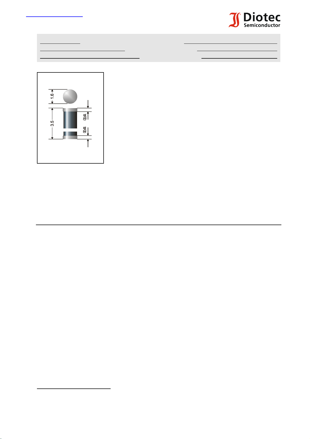
Plastic case MiniMELF SOD-80
Kunststoffgehäuse MiniMELF DO-213AA
Weight approx. – Gewicht ca. 0.04 g
Plastic material has UL classification 94V-0
Gehäusematerial UL94V-0 klassifiziert
Standard packaging taped in ammo pack see page 18
Dimensions / Maße in mm
Standard Lieferform gegurtet in Ammo-Pack siehe Seite 18
Marking: One blue ring denotes “cathode” and “TVS-Diode family”
The type numbers are noted only on the lable on the reel
Kennzeichnung: Ein blauer Ring kennzeichnet “Kathode” und “TVS-Dioden-Familie”
Die Typenbezeichnungen sind nur auf dem Rollenaufkleber vermerkt
Maximum ratings and Characteristics Grenz- und Kennwerte
Peak pulse power dissipation (10/1000 :s waveform) TA = 25/CP
PPM
150 W 1)
Impuls-Verlustleistung (Strom-Impuls 10/1000 :s)
Steady state power dissipation TA = 25/CP
M(AV)
500 mW 2)
Verlustleistung im Dauerbetrieb
Peak forward surge current, 60 Hz half sine-wave TA = 25/CI
FSM
20 A 3)
Stoßstrom für eine 60 Hz Sinus-Halbwelle
Max. instantaneous forward voltage I
= 10A V
F
F
< 3.5 V 3)
Augenblickswert der Durchlaßspannung
Operating junction temperature – Sperrschichttemperatur T
Storage temperature – Lagerungstemperatur T
– 50…+150/C
j
– 50…+150/C
S
Thermal resistance junction to ambient air R
Wärmewiderstand Sperrschicht – umgebende Luft
Thermal resistance junction to terminal R
Wärmewiderstand Sperrschicht – Kontaktfläche
1
) Non-repetitive current pulse see curve I
Höchstzulässiger Spitzenwert eines einmaligen Strom-Impulses, siehe Kurve I
2
) Mounted on P.C. board with 25 mm2 copper pads at each terminal
Montage auf Leiterplatte mit 25 mm2 Kupferbelag (Lötpad) an jedem Anschluß
3
) Unidirectional diodes only – nur für unidirektionale Dioden
07.01.2003
PPM
= f (tr)
PPM
= f (tr)
< 150 K/W 2)
thA
thT
< 60 K/W
1
Page 2
TGL 34-6.8 ... TGL 34-200CA
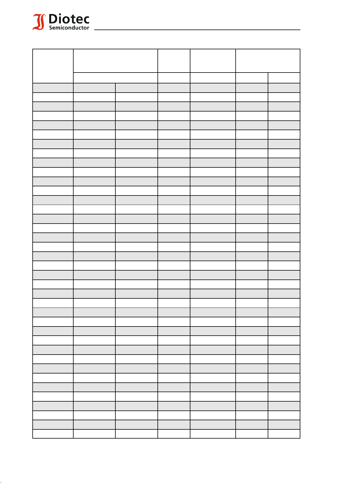
Maximum ratings Grenzwerte
Type
Typ
Breakdown voltage at IT = 1 mA
Abbruch-Spanng. bei I
*) at / bei I
T
= 10 mA
T
= 1 mA
VBR [V] VWM [V] ID [:A] VC [V] I
Stand-off
voltage
Sperrspg.
Max. rev. current
Max. Sperrstrom
at / bei V
WM
Max. clamping voltage
Max. Begrenzerspanng.
at / bei I
(10/1000:s)
PPM
PPM
[A]
TGL34-6.8 6.8 ± 10% 6.12...7.48 *) 5.5 1000 10.8 13,9
TGL34-6.8A 6.8 ± 5% 6.45...7.14 *) 5.8 1000 10.5 14,3
TGL34-7.5 7.5 ± 10% 6.75...8.25 *) 6.0 500 11.7 12,8
TGL34-7.5A 7.5 ± 5% 7.13...7.88 *) 6.4 500 11.3 13,3
TGL34-8.2 8.2 ± 10% 7.38...9.02 *) 6.6 200 12.5 12,0
TGL34-8.2A 8.2 ± 5% 7.79...8.61 *) 7.0 200 12.1 12,4
TGL34 9.1 9.1 ± 10% 8.19...10.0 7.3 50 13.8 10,9
TGL34-9.1A 9.1 ± 5% 8.65...9.55 7.7 50 13.4 11,2
TGL34-10 10 ± 10% 9.0...11.0 8.1 10 15.0 10,0
TGL34-10A 10 ± 5% 9.5...10.5 8.5 10 14.5 10,3
TGL34-11 11 ± 10% 9.9...12.1 8.9 5 16.2 9,3
TGL34-11A 11 ± 5% 10.5...11.6 9.4 5 15.6 9,6
TGL34-12 12 ± 10% 10.8...13.2 9.7 5 17.3 8,7
TGL34-12A 12 ± 5% 11.4...12.6 10.2 5 16.7 9,0
TGL34-13 13 ± 10% 11.7...14.3 10.5 5 19.0 7,9
TGL34-13A 13 ± 5% 12.4...13.7 11.1 5 18.2 8,2
TGL34-15 15 ± 10% 13.5...16.5 12.1 5 22.0 6,8
TGL34-15A 15 ± 5% 14.3...15.8 12.8 5 21.2 7,1
TGL34-16 16 ± 10% 14.4...17.6 12.9 5 23.5 6,4
TGL34-16A 16 ± 5% 15.2...16.8 13.6 5 22.5 6,7
TGL34-18 18 ± 10% 16.2...19.8 14.5 5 26.5 5,7
TGL34-18A 18 ± 5% 17.1...18.9 15.3 5 25.5 5,9
TGL34-20 20 ± 10% 18.0...22.0 16.2 5 29.1 5,2
TGL34-20A 20 ± 5% 19.0...21.0 17.1 5 27.7 5,4
TGL34-22 22 ± 10% 19.8...24.2 17.8 5 31.9 4,7
TGL34-22A 22 ± 5% 20.9...23.1 18.8 5 30.6 4,9
TGL34-24 24 ± 10% 21.6...26.4 19.4 5 34.7 4,3
TGL34-24A 24 ± 5% 22.8...25.2 20.5 5 33.2 4,5
TGL34-27 27 ± 10% 24.3...29.7 21.8 5 39.1 3,8
TGL34-27A 27 ± 5% 25.7...28.4 23.1 5 37.5 4,0
TGL34-30 30 ± 10% 27.0...33.0 24.3 5 43.5 3,4
TGL34-30A 30 ± 5% 28.5...31.5 25.6 5 41.4 3,6
TGL34-33 33 ± 10% 29.7...36.3 26.8 5 47.7 3,1
TGL34-33A 33 ± 5% 31.4...34.7 28.2 5 45.7 3,3
TGL34-36 36 ± 10% 32.4...39.6 29.1 5 52.0 2,9
TGL34-36A 36 ± 5% 34.2...37.8 30.8 5 49.9 3,0
TGL34-39 39 ± 10% 35.1...42.9 31.6 5 56.4 2,7
TGL34-39A 39 ± 5% 37.1...41.0 33.3 5 53.9 2,8
For bidirectional types (suffix “C” or “CA”) electrical characteristics apply in both directions
2
F:\Data\Wp\DatBlatt\Einzelblätter\tgl34.wpd
Page 3

TGL 34-6.8 ... TGL 34-200CA
Maximum ratings Grenzwerte
Type
Typ
Breakdown voltage at IT = 1 mA
Abbruch-Spanng. bei I
*) at / bei I
T
= 10 mA
T
= 1 mA
VBR [V] VWM [V] ID [:A] VC [V] I
Stand-off
voltage
Sperrspg.
Max. rev. current
Max. Sperrstrom
at / bei V
WM
Max. clamping voltage
Max. Begrenzerspanng.
at / bei I
(10/1000:s)
PPM
PPM
TGL34-43 43 ± 10% 38.7...47.3 34.8 5 61.9 2,4
TGL34-43A 43 ± 5% 40.9...45.2 36.8 5 59.3 2,5
TGL34-47 47 ± 10% 42.3...51.7 38.1 5 67.8 2,2
TGL34-47A 47 ± 5% 44.7...49.4 40.2 5 64.8 2,3
TGL34-51 51 ± 10% 45.9...56.1 41.3 5 73.5 2,0
TGL34-51A 51 ± 5% 48.5...53.6 43.6 5 70.1 2,1
TGL34-56 56 ± 10% 50.4...61.6 45.4 5 80.5 1,9
TGL34-56A 56 ± 5% 53.2...58.8 43.6 5 77.0 1,9
TGL34-62 62 ± 10% 55.8...68.8 50.2 5 89.0 1,7
TGL34-62A 62 ± 5% 58.9...65.1 53.0 5 85.0 1,8
TGL34-68 68 ± 10% 61.2...74.8 55.1 5 98.0 1,5
TGL34-68A 68 ± 5% 64.6...71.4 58.1 5 92.0 1,6
TGL34-75 75 ± 10% 67.5...82.5 60.7 5 108 1,4
TGL34-75A 75 ± 5% 71.3...78.8 64.1 5 103 1,5
TGL34-82 82 ± 10% 73.8...90.2 66.4 5 118 1,3
TGL34-82A 82 ± 5% 77.9...86.1 70.1 5 113 1,3
TGL34-91 91 ± 10% 81.9...100 73.7 5 131 1,1
TGL34-91A 91 ± 5% 86.5...95.5 77.8 5 125 1,2
TGL34-100 100 ± 10% 90.0...110 81.0 5 144 1,0
TGL34-100A 100 ± 5% 95.0...105 85.5 5 137 1,1
TGL34-110 110 ± 10% 99.0...121 89.2 5 158 0,9
TGL34-110A 110 ± 5% 105...116 94.0 5 152 1,0
TGL34-120 120 ± 10% 108...132 97.2 5 173 0,9
TGL34-120A 120 ± 5% 114...126 102 5 165 0,9
TGL34-130 130 ± 10% 117...143 105 5 187 0,8
TGL34-130A 130 ± 5% 124...137 111 5 179 0,8
TGL34-150 150 ± 10% 135...165 121 5 215 0,7
TGL34-150A 150 ± 5% 143...158 128 5 207 0,7
TGL34-160 160 ± 10% 144...176 130 5 230 0,7
TGL34-160A 160 ± 5% 152...168 136 5 219 0,7
TGL34-170 170 ± 10% 153...187 138 5 244 0,6
TGL34-170A 170 ± 5% 162...179 145 5 234 0,6
TGL34-180 180 ± 10% 162...198 146 5 258 0,6
TGL34-180A 180 ± 5% 171...189 154 5 246 0,6
TGL34-200 200 ± 10% 180...220 162 5 287 0,5
TGL34-200A 200 ± 5% 190...210 171 5 274 0,5
[A]
For bidirectional types (suffix “C” or “CA”) electrical characteristics apply in both directions
Für bidirektionale Dioden (Suffix “C” oder “CA”) gelten die el. Werte in beiden Richtungen
07.01.2003
3
Page 4

TGL 34-6.8 ... TGL 34-200CA
1
The order of type numbers is graded to the international E 24 standard. The standard tolerance of
the breakdown voltage for each type is ± 10%. Suffix “A” denotes a tolerance of ± 5% for the
breakdown voltage.
e.g.: TGL 34-91CA = bidirectional diode, VBR = 91 V (± 5%), VWM $ 77.8 V at ID = 5 :A
TGL 34-8.2A = unidirectional diode, VBR = 8.2 V (± 5%), VWM $ 7.0 V at ID = 200 :A
Die Abstufung der Typen innerhalb der Reihe entspricht dem internationalen E 24-Standard. Die
Toleranz der Arbeitsspannung jedes einzelnen Typs beträgt in der Standardausführung ± 10%.
Suffix “A” kennzeichnet eine Toleranz der Arbeitsspannung von ± 5%.
z.B.: TGL 34-91CA = bidirectionale Diode, VBR = 91 V (± 5%), VWM $ 77.8 V bei ID = 5 :A
TGL 34-8.2A = unidirectionale Diode, VBR = 8.2 V (± 5%), VWM $ 7.0 V bei ID = 200 :A
1
) Mounted on P.C. board with 25 mm2 copper pads at each terminal
Montage auf Leiterplatte mit 25 mm2 Kupferbelag (Lötpad) an jedem Anschluß
4
F:\Data\Wp\DatBlatt\Einzelblätter\tgl34.wpd
 Loading...