

Page 1
Advance Product Information
August 29, 2000
20 - 40 GHz X3 Frequency Multiplier TGC1430G
Key Features and Performance
• 0.25um pHEMT Technology
• 20 - 40 GHz Output Frequencies
• 8.5 - 13.5 GHz Fundamental Frequencies
• -15 +/- 2dB Conversion Gain
• 18 dBm Input Drive Optimum
• 15dB Fundamental Isolation
• 30dB 2nd Harmonic Isolation
Primary Applications
Chip Dimensions 1.50 mm x 2.0 mm
• Point-to-Point Radio
• Point-to-Multipoint Communications
0
-5
-10
-15
-20
-25
-30
Conversion Gain (dB)
-35
6 8 10 12 14
Input Frequency (GHz)
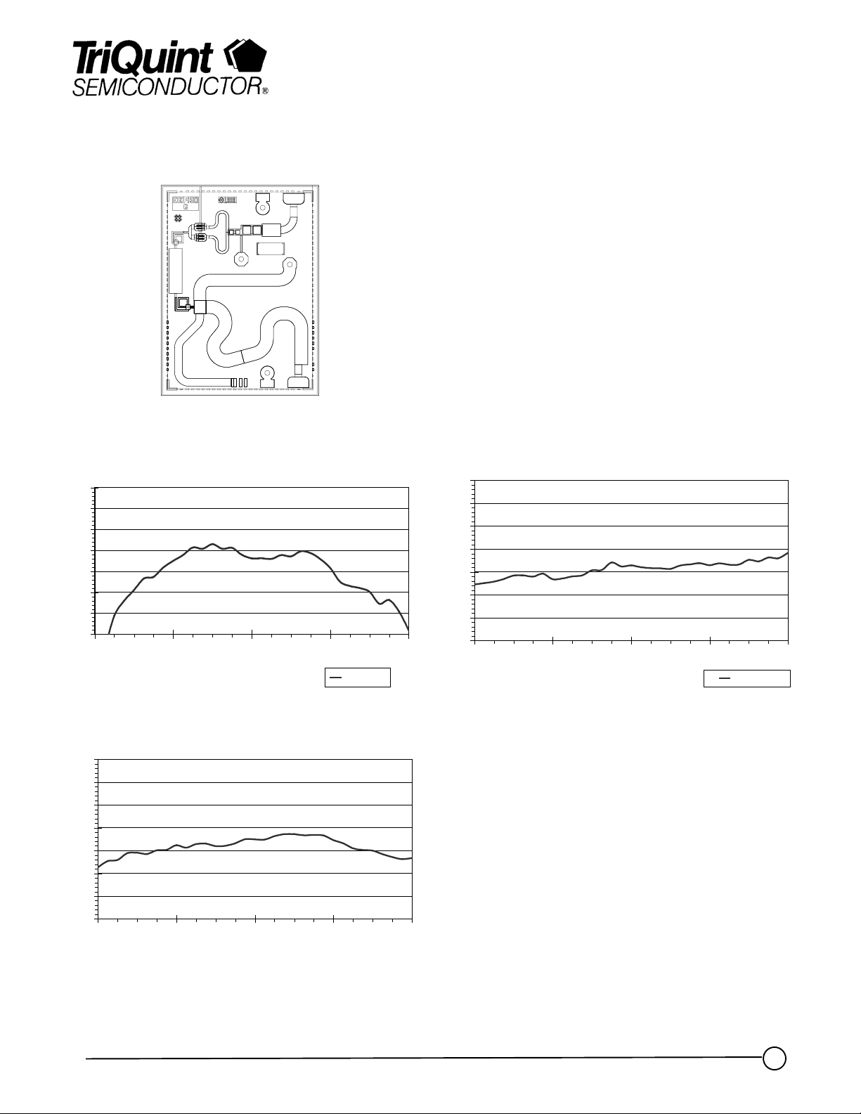
Conversion Gain vs Input Frequency (Input @ 18dBm) Fundamental Isolation
0
-10
-20
-30
-40
-50
-60
2nd Harmonic Suppression (dB)
-70
6 8 10 12 14
Input Frequency (GHz)
+18dBm
0
-5
-10
-15
-20
Isolation (dB)
-25
-30
-35
6 8 10 12 14
Input Frequency (GHz)
+18dBm
2nd Harmonic Suppression
Note: Devices designated as EPU are typically early in their characterization process prior to finalizing all electrical and process
specifications. Specifications subject to change without notice
TriQuint Semiconductor Texas : Phone (972)994-8465 Fax (972)994 8504 Web: www.triquint.com
1
Page 2
Advance Product Information
August 29, 2000
TGC1430G
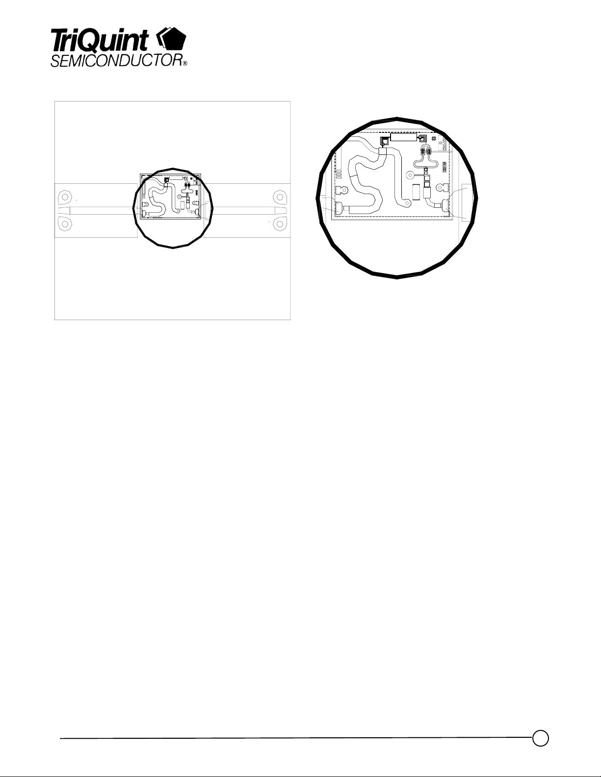
TGC1430G - Recommended Assembly Drawing
Note: Devices designated as EPU are typically early in their characterization process prior to finalizing all electrical and process
specifications. Specifications subject to change without notice
TriQuint Semiconductor Texas : Phone (972)994-8465 Fax (972)994 8504 Web: www.triquint.com
Page 3

Advance Product Information
Assembly Process Notes
Reflow process assembly notes:
•=
AuSn (80/20) solder with limited exposure to temperatures at or above 300ΓC
•=
alloy station or conveyor furnace with reducing atmosphere
•=
no fluxes should be utilized
•=
coefficient of thermal expansion matching is critical for long-term reliability
•=
storage in dry nitrogen atmosphere
Component placement and adhesive attachment assembly notes:
•=
vacuum pencils and/or vacuum collets preferred method of pick up
•=
avoidance of air bridges during placement
•=
force impact critical during auto placement
•=
organic attachment can be used in low-power applications
•=
curing should be done in a convection oven; proper exhaust is a safety concern
•=
microwave or radiant curing should not be used because of differential heating
•=
coefficient of thermal expansion matching is critical
August 29, 2000
TGC1430G
Interconnect process assembly notes:
•=
thermosonic ball bonding is the preferred interconnect technique
•=
force, time, and ultrasonics are critical parameters
•=
aluminum wire should not be used
•=
discrete FET devices with small pad sizes should be bonded with 0.0007-inch wire
•=
maximum stage temperature: 200ΓC
GaAs MMIC devices are susceptible to damage from Electrostatic Discharge. Proper precautions should
be observed during handling, assembly and test.
Note: Devices designated as EPU are typically early in their characterization process prior to finalizing all electrical and process
specifications. Specifications are subject to change without notice.
TriQuint Semiconductor Texas : Phone (972)994-8465 Fax (972)994 8504 Web: www.triquint.com
 Loading...