

Page 1
Advance Product Information
May 3, 2000
17-21 GHz Intermediate Power Amplifier TGA9088A-EPU
Key Features and Performance
• 0.25um pHEMT Technology
• 17-21GHz Frequency Range
• 22 dBm @ P2dB Nominal Pout
• 18.5 dBm Nominal Gain
• IRL>18 dB, ORL>10 dB
• 7V, 66mA Self Bias
Primary Applications
Chip Dimensions 2.41mm x 1.52 mm x 0.1mm
• Satellite Systems
• Point-to-Point Radio
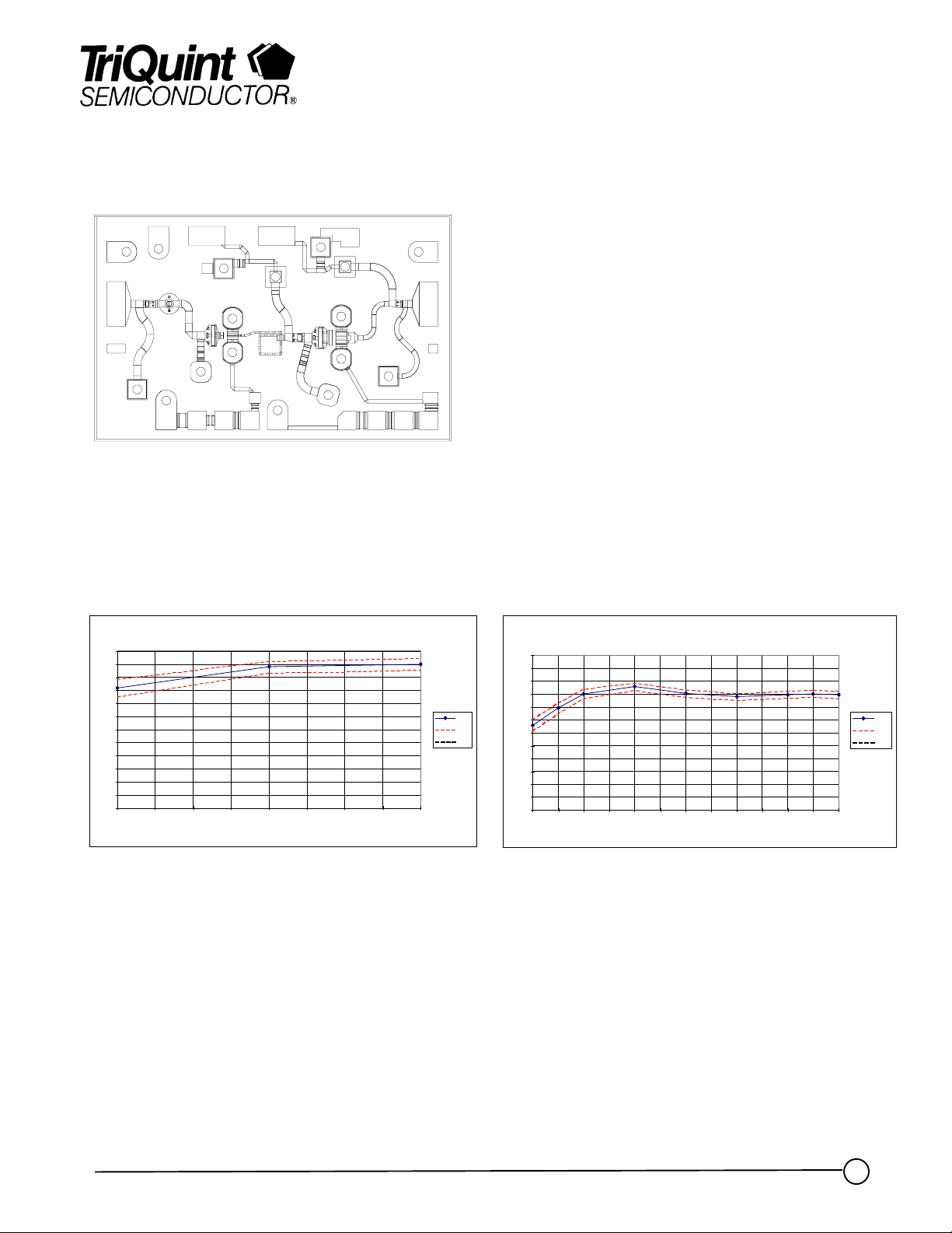
EG1901A (TGA9088A), LOT # 9733701-1,2, 3: On-Wafe r-Testi ng (1640 Devi ces)
24
22
20
18
16
14
12
(dBm)
10
8
6
4
Output Power @ 2dB Compression
2
0
17.0 17. 5 18. 0 18.5 19.0 19. 5 20.0 20.5 2 1.0
Self Bias @ V+ = 5V, Vd = 7V, Id >= 56 mA
Frequency (GHz)
Measured Pout at 2dB Gain Compression
mean
X-s
X+s
EG1901A (TGA9088A), LOT # 9733701-1, 2,3: On-Wa fer-Te sting (1640 Devices)
24
22
20
18
16
14
12
10
Gain (dB)
8
6
4
2
0
16.0 16.5 17.0 17.5 18.0 18.5 19.0 19.5 20.0 20.5 21.0 21.5 22.0
Self Bias @ V+ = 5V, Vd = 7V, Id >= 56 mA
Frequ ency (GHz)
Measured Small Signal Gain
mea n
X-s
X+s
Note: Devices designated as EPU are typically early in their characterization process prior to finalizing all electrical and process
specifications. Specifications are subject to change without notice
TriQuint Semiconductor Texas : Phone (972)994 8465 Fax (972)994 8504 Web: www.triquint.com
1
Page 2

Advance Product Information
May 3, 2000
TGA9088A
Note: Devices designated as EPU are typically early in their characterization process prior to finalizing all electrical and process
specifications. Specifications are subject to change without notice
TriQuint Semiconductor Texas : Phone (972)994 8465 Fax (972)994 8504 Web: www.triquint.com
Page 3

Advance Product Information
May 3, 2000
TGA9088A
Chip Assembly and Bonding Diagram
GaAs MMIC devices are susceptible to damage from Electrostatic Discharge. Proper precautions should
be observed during handling, assembly and test.
Note: Devices designated as EPU are typically early in their characterization process prior to finalizing all electrical and process
specifications. Specifications are subject to change without notice
TriQuint Semiconductor Texas : Phone (972)994 8465 Fax (972)994 8504 Web: www.triquint.com
Page 4

Advance Product Information
Assembly Process Notes
Reflow process assembly notes:
•=
AuSn (80/20) solder with limited exposure to temperatures at or above 300ΓC
•=
alloy station or conveyor furnace with reducing atmosphere
•=
no fluxes should be utilized
•=
coefficient of thermal expansion matching is critical for long-term reliability
•=
storage in dry nitrogen atmosphere
Component placement and adhesive attachment assembly notes:
•=
vacuum pencils and/or vacuum collets preferred method of pick up
•=
avoidance of air bridges during placement
•=
force impact critical during auto placement
•=
organic attachment can be used in low-power applications
•=
curing should be done in a convection oven; proper exhaust is a safety concern
•=
microwave or radiant curing should not be used because of differential heating
•=
coefficient of thermal expansion matching is critical
May 3, 2000
TGA9088A
Interconnect process assembly notes:
•=
thermosonic ball bonding is the preferred interconnect technique
•=
force, time, and ultrasonics are critical parameters
•=
aluminum wire should not be used
•=
discrete FET devices with small pad sizes should be bonded with 0.0007-inch wire
•=
maximum stage temperature: 200ΓC
GaAs MMIC devices are susceptible to damage from Electrostatic Discharge. Proper precautions should
be observed during handling, assembly and test.
Note: Devices designated as EPU are typically early in their characterization process prior to finalizing all electrical and process
specifications. Specifications are subject to change without notice.
TriQuint Semiconductor Texas : Phone (972)994 8465 Fax (972)994 8504 Web: www.triquint.com
 Loading...