

Page 1
TGA9083-EEU Power Amplifier
6.5 to 11.5-GHz Frequency Range
●
5-Watt Output Power at 7V , 6-W at 8V, 8-W at 9 Volt Drain Bias
●
19-dB Typical Small Signal Gain
●
40% Power Added Efficiency at 7V, 35% PAE at 9 Volt Drain Bias
●
12-dB Typical Input Return Loss, 9- dB Typical Output Return Loss
●
On-Chip Active Gate Bias Circuit Option Simplifies Biasing
●
4, 521 x 3,048 x 0,100 mm (0.178 x 0.120 x 0.004 in.)
●
PHOTO ENLARGEMENT
O R , I N C .T R I Q U I N T S E M I C O N D U C T
9083
DESCRIPTION
TriQuint Semiconductor, Inc. • Texas Facilities • (972) 995-8465
The TriQuint TGA9083 - EEU is a monolithic power amplifier which operates from 6.5 to
11.5 GHz. This device is currently classified as an Engineering Evaluation Unit. This t wo stage power
amplifier partially consists of a 2.5 -mm pHEMT driving a 11.36 -mm pHEMT at the output. The
TGA9083-EEU is capable of providing 8 Watts of output power with 35% PAE when biased at 9 Volts.
Typical 7 Volts operation provides 5 Watts of output power with a power-added efficiency of 40
percent. Typical small signal gain is 19-dB. In balanced configuration, 12 Watts of output power is
achievable with 40% PAE.
The TGA9083-EEU is fabricated using TI’s 0.25um T-gate power pHEMT process. This device offer s
either standard gate biasing or an on-chip active gate bias circuit which simplifies gate biasing. The
active gate bias (AGB) circuit requires a - 5 V supply. This amplifier's output power and high efficiency
over 6.5 to 11.5 GHz make it a viable power amp solution in applications such as point-to-point radio ,
phased-array radar, and telecommunications.
Bond pad and backside metallization is gold plated for compa tibility with eutectic alloy attachment
methods as well as with thermocompression and thermosonic wire -bonding processes.
The TGA9083 - EEU is supplied in chip for m and is readily assembled using automated equipment.
Ground is provided to the circuitr y through vias to the backside metallization.
• www.triquint.com
Page 2
TGA9083-EEU
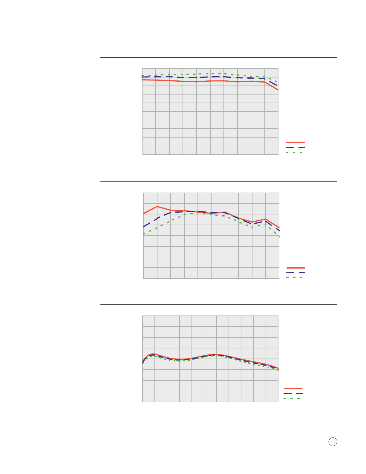
TYPICAL
OUTPUT POWER
TYPICAL
POWER-ADDED
EFFICIENCY
40
38
36
34
32
30
28
Pout (dBm)
26
24
22
20
6.5 7.0 7.5 8.0 8.5 9.0 9.5 10.0 10.5 11.0 11.5
Frequency
(GHz)
50
45
40
35
30
PAE (%)
25
PIN= 21 dBm
= 1.1 A
I
D
= 30 ° C
T
A
Drain Voltage:
P
= 21 dBm
IN
= 1.1 A
I
D
= 30 ° C
T
A
7 V
8 V
9 V
TYPICAL
SMALL SIGNAL GAIN
20
15
10
6.5 7.0 7.5 8.0 8.5 9.0 9.5 10.0 10.5 11.0 11.5
Frequency
(GHz)
40
35
30
25
20
15
10
Small Signal Gain (dB)
5
0
6.0 6.5 7.0 7.5 8.0 8.5 9.0 9.5 10.0 10.5 11.0 11.5
Frequency
(GHz)
Drain Voltage:
ID = 1.1 A
= 30 ° C
T
A
Drain Voltage:
7 V
8 V
9 V
7 V
8 V
9 V
TriQuint Semiconductor, Inc. • Texas Facilities • (972) 995-8465
• www.triquint.com
2
Page 3
TGA9083-EEU
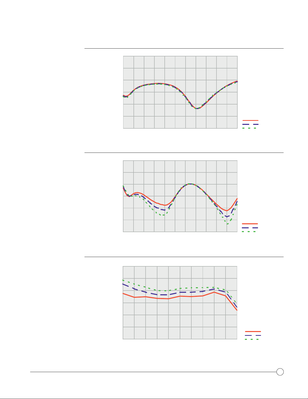
TYPICAL
INPUT RETURN LOSS
TYPICAL
OUTPUT RETURN LOSS
0
5
10
15
20
Input Return Loss (dB)
25
30
6.0 6.5 7.0 7.5 8.0 8.5 9.0 9.5 10.0 10.5 11.0 11.5
Frequency
0
5
10
15
(GHz)
ID = 1.1 A
= 30 ° C
T
A
Drain Voltage:
= 1.1 A
I
D
= 30 ° C
T
A
7 V
8 V
9 V
TYPICAL
DRAIN CURRENT
20
Output Return Loss (dB)
25
30
6.0 6.5 7.0 7.5 8.0 8.5 9.0 9.5 10.0 10.5 11.0 11.5
Frequency
(GHz)
3000
2500
2000
1500
Id (mA)
1000
500
0
6.5 7.0 7.5 8.0 8.5 9.0 9.5 10.0 10.5 11.0 11.5
Frequency
(GHz)
Drain Voltage:
7 V
8 V
9 V
PIN= 21 dBm
= 1.0 to 1.1 A
I
D
= 30 ° C
T
A
Drain Voltage:
7 V
8 V
9 V
TriQuint Semiconductor, Inc. • Texas Facilities • (972) 995-8465
• www.triquint.com
3
Page 4

TGA9083-EEU
ABSOLUTE
MAXIMUM RATINGS
Drain supply voltage, V
...................................................................................................................... 10 V
D
Negative supply voltage range, VG ..............................................................................................-5 V to 0 V
Drain supply current, ID ................................................................................................................ 3.5 A
Power dissipation, PD, at (or below) 25 C base-plate temperature* ........................................................ 39 W
Input continuous wave power, P
.................................................................................................. 25.5 dBm
IN
Operating channel temperature, TCH** ......................................................... ..................................... 150 C
Mounting temperature (30 sec), TM .................................................................................................. 320 C
Storage temperature range, T
Ratings over operating channel temperature range, TCH(unless otherwise noted)
............................................................................................-65 to 150 C
STG
Stresses beyond those listed under “Absolute Maximum Ratings” ma y cause permanent damage to the de vice.
These are stress ratings only, and functional operation of the de vice at these or an y other conditions beyond
those indicated under “RF Characteristics” is not implied. E xposure to absolute maximum rated conditions for
extended periods may affect device reliability.
* For operation above 25 C base- plate temperature, derate linearly at the rate of 73 mW/ C.
** Operating channel temperature directly affects the de vice MTTF. For maximum life, it is recommended that
channel temperature be maintained at the low est possible level.
TriQuint Semiconductor, Inc. • Texas Facilities • (972) 995-8465
• www.triquint.com
4
Page 5

TGA9083-EEU
TYPICAL S-PARAMETERS
Frequency S11 S21 S12 S22
(GHz) dB ANG(°) dB ANG(°) dB ANG(°) dB ANG(°)
6.5 -14.31 -78.1 21.77 168.2 -64.33 88.1 -14.44 114.4
6.6 -13.64 -94.1 21.69 146.0 -60.56 81.2 -14.21 89.3
6.7 -13.08 -107.7 21.42 125.7 -58.66 70.2 -14.24 69.1
6.8 -12.72 -118.8 21.09 107.0 -57.67 59.6 -14.50 50.1
6.9 -12.36 -128.4 20.74 89.7 -57.01 48.2 -14.91 34.3
7.0 -12.15 -136.9 20.40 73.4 -56.72 37.4 -15.53 17.3
7.1 -11.94 -144.3 20.12 57.9 -56.97 28.1 -16.28 1.9
7.2 -11.81 -151.0 19.88 43.1 -57.08 20.2 -16.99 -14.2
7.3 -11.71 -157.2 19.69 28.9 -57.77 11.7 -17.83 -30.1
7.4 -11.62 -163.0 19.55 14.9 -57.76 4.5 -18.52 -46.3
7.5 -11.54 -168.6 19.48 1.3 -57.76 -5.0 -19.16 -61.9
7.6 -11.48 -174.6 19.44 -12.1 -57.71 -14.8 -19.83 -75.8
7.7 -11.46 179.6 19.45 -25.4 -58.13 -28.3 -20.05 -88.6
7.8 -11.49 173.5 19.51 -38.6 -58.49 -39.3 -20.59 -98.0
7.9 -11.56 167.5 19.61 -51.8 -58.82 -50.7 -20.68 -105.8
8.0 -11.64 161.1 19.75 -65.0 -58.75 -62.5 -20.89 -108.7
8.1 -11.84 154.7 19.93 -78.4 -59.10 -79.3 -20.52 -109.5
8.2 -12.00 148.0 20.16 -92.1 -59.09 -95.6 -19.67 -108.5
8.3 -12.27 140.8 20.41 -106.1 -59.22 -113.4 -18.60 -107.9
8.4 -12.59 133.2 20.67 -120.4 -58.89 -133.1 -17.09 -109.5
8.5 -13.03 124.8 20.93 -135.0 -58.80 -149.5 -15.59 -112.4
8.6 -13.55 115.8 21.18 -150.0 -58.78 -170.2 -14.14 -117.2
8.7 -14.20 106.2 21.39 -165.3 -58.42 173.1 -12.89 -124.4
8.8 -15.00 95.7 21.56 179.2 -58.06 152.0 -11.82 -132.0
8.9 -15.96 84.3 21.67 163.6 -57.95 133.7 -10.98 -141.0
9.0 -16.95 72.4 21.72 147.9 -57.57 114.0 -10.41 -150.3
9.1 -18.19 59.3 21.71 132.2 -57.49 93.9 -9.98 -160.1
9.2 -19.31 45.4 21.63 116.7 -57.13 77.9 -9.83 -170.4
9.3 -20.44 29.9 21.49 101.3 -57.62 59.4 -9.84 179.4
9.4 -21.28 14.1 21.30 86.3 -57.57 40.5 -10.03 168.5
9.5 -21.77 -3.6 21.07 71.4 -57.59 20.7 -10.44 158.1
9.6 -21.75 -19.6 20.81 56.8 -57.61 3.4 -10.91 147.1
9.7 -21.45 -35.6 20.52 42.5 -57.36 -15.4 -11.62 136.0
9.8 -20.72 -48.2 20.24 28.3 -57.08 -32.3 -12.32 124.6
9.9 -19.95 -58.9 19.95 14.3 -56.69 -51.1 -13.23 112.1
10.0 -19.15 -68.3 19.67 0.4 -56.18 -64.5 -14.16 100.1
10.1 -18.33 -76.7 19.38 -13.4 -55.71 -80.0 -15.11 86.9
10.2 -17.51 -84.1 19.11 -27.2 -54.67 -92.3 -16.20 73.2
10.3 -16.67 -91.4 18.86 -41.1 -54.34 -106.2 -17.11 59.2
10.4 -15.95 -98.1 18.61 -55.0 -53.49 -119.4 -18.22 43.6
10.5 -15.23 -104.5 18.37 -69.0 -53.00 -133.6 -19.22 28.4
10.6 -14.62 -110.8 18.13 -83.0 -52.35 -144.6 -20.24 11.4
10.7 -13.99 -117.4 17.89 -97.2 -51.80 -155.4 -21.37 -7.1
10.8 -13.41 -123.9 17.65 -111.8 -51.56 -166.5 -22.33 -26.6
10.9 -12.87 -130.8 17.42 -126.3 -51.12 -178.6 -23.12 -50.8
11.0 -12.39 -137.8 17.17 -141.0 -50.77 170.8 -23.74 -75.6
11.1 -11.97 -145.6 16.93 -156.2 -50.69 159.1 -23.25 -104.2
11.2 -11.57 -153.5 16.64 -171.4 -50.33 147.9 -22.17 -131.1
11.3 -11.21 -162.1 16.34 173.1 -50.57 136.5 -20.63 -153.4
11.4 -10.91 -171.2 16.00 157.3 -50.76 124.9 -18.89 -174.0
11.5 -10.63 179.2 15.63 141.4 -50.93 112.2 -17.29 168.8
TA= 25 ° C, VD= +8 V , ID= 1.1 A
Reference planes for S - parameter data include bond wires as specified in the “Recom mended Assembly Diagram.”
TriQuint Semiconductor, Inc. • Texas Facilities • (972) 995-8465
• www.triquint.com
5
Page 6

TGA9083-EEU
RF CHARACTERISTICS
THERMAL INFORMATION
EQUIVALENT
SCHEMATIC
PARAMETER TEST CONDITIONS TYP UNIT
GP Small Signal Power Gain 6.5 to 11.5 GHz 9 dB
IRL Input Return Loss 6.5 to 11.5 GHz 12 dB
ORL Output Return Loss 6.5 to 11.5 GHz 9 dB
PAE Power Added Efficiency 6.5 to 11.5 GHz 40 %
P
Output Power at 2-dB Gain Compression 6.5 to 11.5 GHz 37 dBm
2dB
IP
Output Third-order Intercept Point 6.5 to 11.5 GHz 44 dBm
3
VD=+7 V, ID=1.5 A, TA= 25 ° C unless stated
PARAMETER TEST CONDITIONS NOM UNIT
R
Thermal resistance, channel to backside 25°C Base, VD=9 V, ID=1.2 A, PD=6 W 10 °C/W
JC
-5V
G1
G2
(opt)
Gnd
active
bias
D2
-5V
(opt)
resistive
divider
G1
Q1
2.5mm
G2
Q2
11.36mm
Gnd
Gnd
D2
TriQuint Semiconductor, Inc. • Texas Facilities • (972) 995-8465
• www.triquint.com
6
Page 7

RECOMMENDED
RF OutputRF Input
.01uF
.01uF
VG
VG
Vd
Vd
100 pF
100 pF
100 pF
100pF
100pF
100pF
ASSEMBLY DIAGRAM
TGA9083-EEU
Bond using three (four at RF
performance. Bond wires connected to the RF Output pad should be equal distance from center line as indicated in
drawing. Close placement of exter nal components is essential to stability.
Gate bias ( V
Drain bias ( V
) voltage can be applied from either side of MMIC.
G
) voltage should be connected to both sides of MMIC.
D
) 1.0-mil diameter, 25 to 30-mil length gold bondwires at RF Input and RF Output for optimum
OUT
TriQuint Semiconductor, Inc. • Texas Facilities • (972) 995-8465
• www.triquint.com
7
Page 8

RECOMMENDED
On-chip wire bond
RF Output
RF Input
.01uF
-5 V
Vd
Vd
100pF
100pF
100pF
100pF
100pF
A
B
C
D
E
ASSEMBLY DIAGRAM
USING ACTIVE GATE
BIAS CIRCUIT
TGA9083-EEU
Bond using three (four at RF
performance. Bond wires connected to the RF Output pad should be equal distance from center line as indicated in dra wing.
) 1.0-mil diameter, 25 to 30-mil length gold bondwires at RF Input and RF Output for optimum
OUT
Close placement of external components is essential to stability.
Drain bias ( V
) voltage should be connected to both sides of MMIC.
D
TriQuint Semiconductor, Inc. • Texas Facilities • (972) 995-8465
• www.triquint.com
8
Page 9

TGA9083-EEU
MECHANICAL DRAWING
41.7
5
8
41.7
120.0
115.5
112.0
104.5
97.9
89.5
89.2
86.0
51.5
8.1
5.4
0.0
14.5
4
3
A
B
C
E
D
1
7
0.0
5.9
14.5
Units: millimeters (inches)
Thickness: 0,1016 (0.004) (reference only)
Chip edge to bond pad dimensions are shown to center of bond pad.
Chip size +/- 0,0508 (0.002)
168.4
169.0
178.0
110.0
6
53.5
2
9
9.7
Bond pad #1 (RF Input) Center two bond wires equal distance from center line
Bond pad #2 (RF Output) Center two bond wires equal distance from center line
Bond pad #3 (-V
Bond pad #4, #7 (-V
Bond pad #5, #8 (V
Bond pad #6, #9 (V
) 0,120 x 0,120 (.0047 x .0047)
AGB
) 0,120 x 0,120 (.0047 x .0047)
G
) 0,240 x 0,120 (.0094 x .0047)
D1
) 0,275 x 0,340 (.0108 x .0134)
D2
Bond pads A,B,C,D,E 0,120 x 0,120 (.0047 x .0047)
TriQuint Semiconductor, Inc. • Texas Facilities • (972) 995-8465
• www.triquint.com
9
 Loading...