

Page 1
Product Data Sheet
6 - 18 GHz Power Amplifier TGA8014-SCC
Key Features and Performance
• 6 to 18 GHz Frequency Range
• 11 dB Typical Gain
• Greater Than 0.5 Watt Output Power at
1 dB Gain Compression
• Designed for Balanced Configuration
• Unconditionally Stable
• 3.6068 x 1.9304 x 0.1016 mm (0.142 x
0.076 x 0.004 in.)
Description
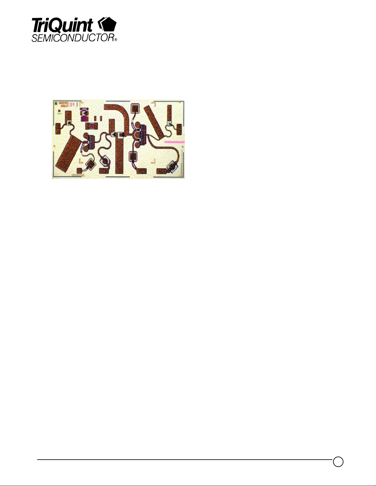
The TriQuint TGA8014-SCC is a two-stage GaAs monolithic medium power
amplifier. Reactively matched 914 um and 1219 um FETS provide 11 dB nominal
gain with 16 percent typical power-added efficiency and output power at 1 dB gain
compression of 0.5 watt. Ground is provided to the circuitry through vias to the
backside metallization.
The small size and inherent reliability advantages of a monolithic device over a
hybrid design make this device attractive for use in a variety of military applications.
Used in a balanced configuration, the TGA8014-SCC effectively addresses
applications such as driver and power stages in EW amplifiers, local oscillator
buffers, and TWT replacement amplifiers.
Bond pad and backside metallization is gold plated for compatibility with eutectic
alloy attachment methods as well as the thermcompression and thermosonic wirebonding processes. The TGA8014-SCC is supplied in chip form and is readily
assembled using automated equipment.
TriQuint Semiconductor Texas Phone: (972)994 8465 Fax: (972)994 8504 Web: www.triquint.com
1
Page 2
Product Data Sheet
TGA8014-SCC
TriQuint Semiconductor Texas Phone: (972)994 8465 Fax: (972)994 8504 Web: www.triquint.com
2
Page 3

Product Data Sheet
TGA8014-SCC
TriQuint Semiconductor Texas Phone: (972)994 8465 Fax: (972)994 8504 Web: www.triquint.com
3
Page 4

Product Data Sheet
TGA8014-SCC
TYPICAL S-PARAMETERS
FREQUENCY
(GHz) MAG ANG MAG ANG MAG ANG M AG ANG (dB)
S
11
S
21
S
12
S
22
GAIN
6.0 0.55 176 3.55 29 0.002 167 0.36 4 11.0
6.5 0.58 173 3.69 -34 0.005 150 0.41 -35 11.3
7.0 0.66 168 3.73 -80 0.006 135 0.48 -73 11.4
7.5 0.73 160 3.98 -120 0.008 119 0.55 -105 12.0
8.0 0.77 150 4.25 -159 0.010 96 0.58 -135 12.6
8.5 0.79 142 4.36 163 0.010 77 0.57 -160 12.8
9.0 0.79 134 4.31 127 0.009 54 0.52 179 12.7
9.5 0.79 127 4.09 93 0.008 33 0.45 164 12.2
10.0 0.80 120 3.81 62 0.006 10 0.40 153 11.6
10.5 0.81 113 3.55 33 0.005 -10 0.38 143 11.0
11.0 0.82 105 3.39 8 0.004 -42 0.36 131 10.6
11.5 0.84 97 3.32 -18 0.004 -82 0.36 119 10.4
12.0 0.85 87 3.32 -42 0.004 -122 0.36 105 10.4
12.5 0.87 77 3.40 -68 0.005 -133 0.37 87 10.6
13.0 0.86 66 3.49 -94 0.006 -152 0.37 70 10.8
13.5 0.85 54 3.70 -121 0.010 180 0.40 52 11.4
14.0 0.82 40 3.89 -151 0.011 155 0.42 30 11.8
14.5 0.76 27 3.92 178 0.012 136 0.42 8 11.9
15.0 0.68 14 3.78 146 0.014 111 0.38 -13 11.6
15.5 0.60 6 3.59 118 0.014 78 0.31 -27 11.1
16.0 0.55 -4 3.43 89 0.015 39 0.28 -37 10.7
16.5 0.52 -16 3.32 59 0.010 -8 0.27 -51 10.4
17.0 0.47 -26 3.28 32 0.009 -4 0.23 -68 10.3
17.5 0.47 -43 3.39 1 0.017 -40 0.23 -88 10.6
18.0 0.46 -69 3.50 -34 0.017 -82 0.25 -119 10.9
= 25oC, V+ = 8 V, I+ = 50% I
T
A
Reference planes for S-parameter data include bond wires as specified in the “Recommended Assembly
Diagram.” The S-parameters are also available on floppy disk and the world wide web.
DSS
RF CHARACTERISTICS
TriQuint Semiconductor Texas Phone: (972)994 8465 Fax: (972)994 8504 Web: www.triquint.com
P ARAMETER TEST CONDITIONS TYP UNIT
G
p
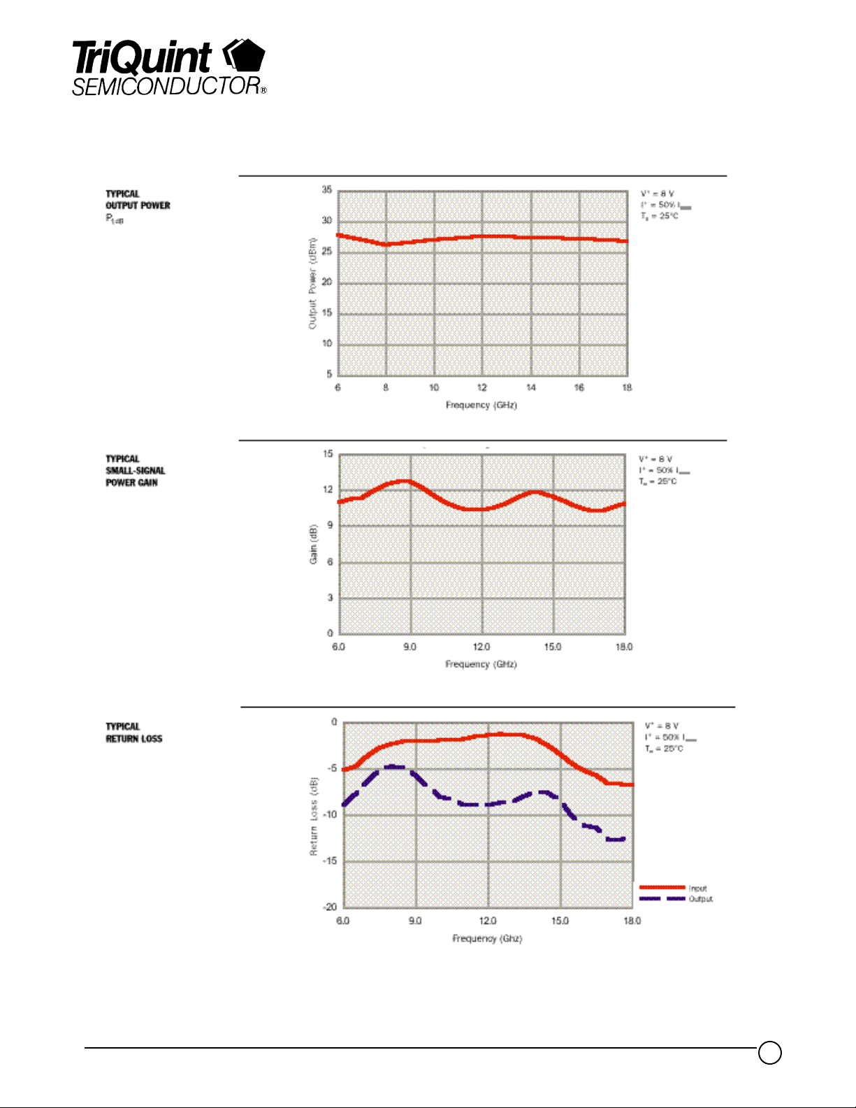
Pow er ga in f = 6 to 18 GHz 11 dB
SWR (in) Input s tanding wave ratio f = 6 to 18 GHz 4.5:1 *
SWR (out) Output standing w a ve ratio f = 6 to 18 GHz 2.2:1 -
P
IP
1dB
3
Output pow e r at 1–dB gain compres s ion f = 6 to 18 GHz 27 dBm
Output third-order interce pt point f = 10 GHz 36.7 dBm
f = 18 GHz 36.7
TA = 25oC, V+ = 8 V, I+ = 50% I
DSS
* The TGA8014-SCC is intended strictly for use in a balanced configuration.
4
Page 5

Product Data Sheet
TGA8014-SCC
THERMAL INFORMATION
EQUIVALENT SCHEMATIC
RECOMMENDED
ASSEMBLY DIAGRAM
P ARAMETER TEST CONDITION NOM UNIT
R
Thermal resistance (channel to backside)
θ
JC
+
V
= 8 V, I
+
= 50 % I
DS S
30 °C/W
________
RF connections: Bond two 1-mil diameter, 25-mil-length gold bond wires at both RF Input and RF Output
for optimum RF performance.
Close placement of external components is essential to stability.
Refer to TriQuint’s Recommended Assembly Instructions for GaAs Products.
TriQuint Semiconductor Texas Phone: (972)994 8465 Fax: (972)994 8504 Web: www.triquint.com
5
Page 6

MECHANICAL DRAWING
Product Data Sheet
TGA8014-SCC
GaAs MMIC devices are susceptible to damage from Electrostatic Discharge. Proper precautions should be observed
during handling, assembly and test.
TriQuint Semiconductor Texas Phone: (972)994 8465 Fax: (972)994 8504 Web: www.triquint.com
6
 Loading...