

Page 1
Advance Product Information
2 -20 GHz Wideband AGC Amplifier TGA1342-EPU
Key Features and Performance
• 0.5 um MESFET Technology
• 9 dB Nominal Gain
• 3.5 dB NF Typical Midband
• 17.5 dBm Nominal Pout @ P1dB
• Bias 5-8V @ 60 mA
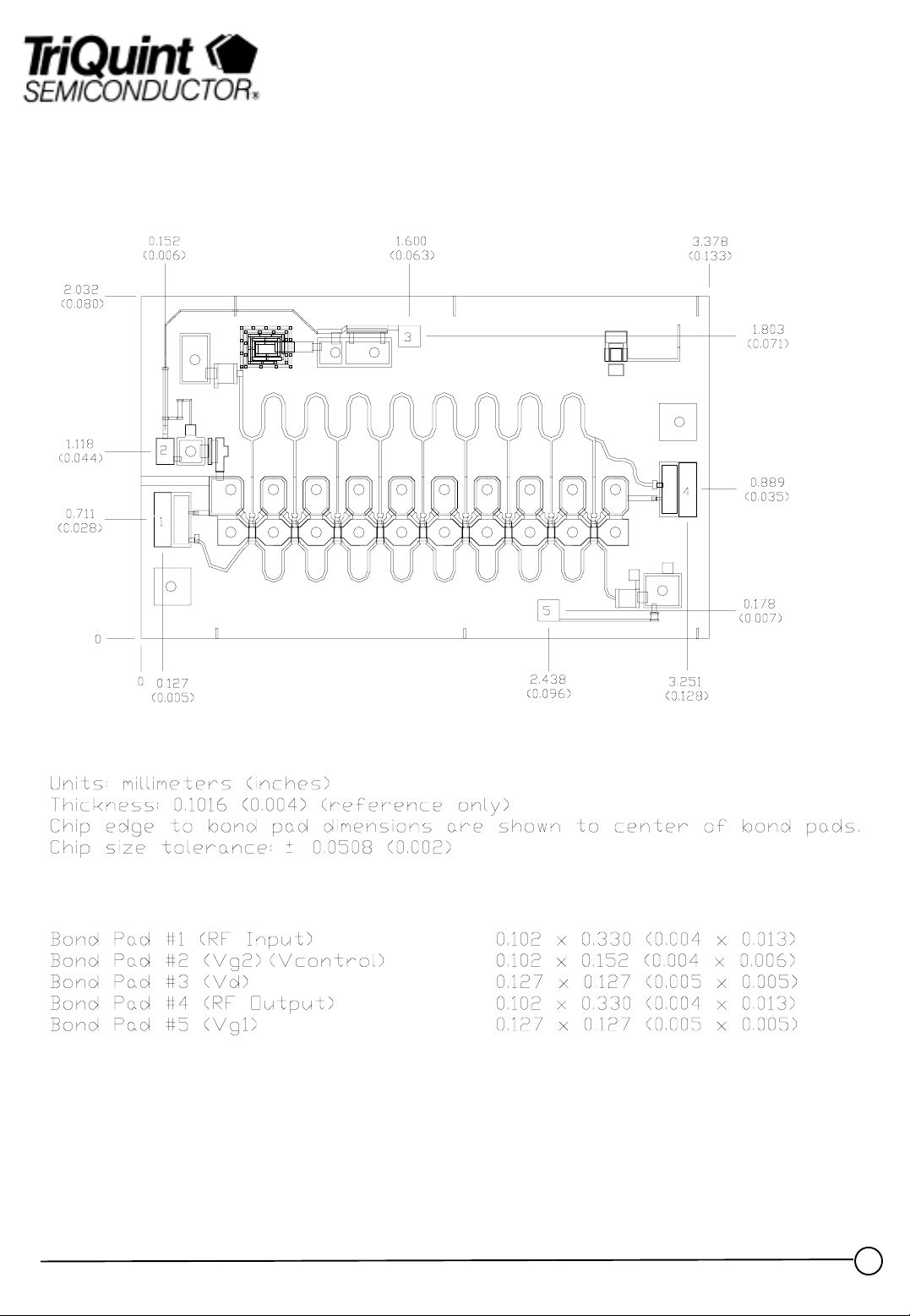
• Dimensions 3.378mm x 2.032mm
Primary Applications
• Wideband Gain Block Amplifier
• Wideband Low Noise Amplifier
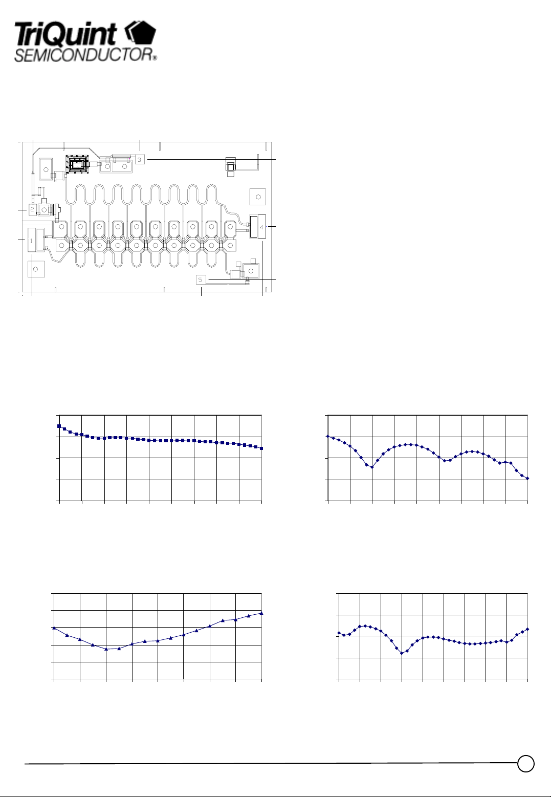
Typical Electrical Characteristics
S21 Gain (dB)
VD=5v Id= 60m a Temp=25C
12.0
10.0
8.0
Gain (dB)
6.0
4.0
2 4 6 8 101214161820
Frequency (GHz)
Noise Fi gure (dB )
VD=6v Id= 60ma Temp=25C
6.0
5.0
4.0
3.0
2.0
Noise Figure (dBf)
1.0
2 4 6 8 10 12 14 16 18
Frequency (GHz)
S11 Input Ret urn Loss ( dB)
VD=5v Id= 60ma Temp=25C
0.0
-10.0
-20.0
-30.0
-40.0
Input Return Loss (dB)
2 4 6 8 10 12 14 16 18 20
S22 Output Return Loss (dB)
VD=5v Id= 60m a Temp=25C
0.0
-10.0
-20.0
(dB)
-30.0
Output Return Loss
-40.0
2 4 6 8 10 12 14 16 18 20
Frequency (GHz)
Frequency (GHz)
Note: Devices designat e d as EPU are typically earl y in their char a cterization process prior to finalizing all electric al and process
specifications. Specifications are subje ct to change without notice
TriQuint Semiconductor Texas : Phone (972)994-8465 Fax (972)994 8504 Web: www.triquint.com
1
rev 11/10/98
Page 2
Advance Product Information
Mechanical Characteristics
Note: Devices designat e d as EPU are typically earl y in their char a cterization process prior to finalizing all electric al and process
specifications. Specifications are subje ct to change without notice.
TriQuint Semiconductor Texas : Phone (972)994-8465 Fax (972)994 8504 Web: www.triquint.com
rev 11/10/98
2
Page 3

Chip Assembly and Bonding Diagram
Advance Product Information
TriQuint Semiconductor Texas : Phone (972)994-8465 Fax (972)994 8504 Web: www.triquint.com
3
rev 11/10/98
Page 4

Reflow process assembly notes:
•=
AuSn (80/20) solder with limited exposure to temperatures at or above 300ΓC
•=
alloy station or conveyor furnace with reducing atmosphere
•=
no fluxes should be utilized
•=
coefficient of thermal expansion matching is critical for long-term reliability
•=
storage in dry nitrogen atmosphere
Component placement and adhesive attachment assembly notes:
•=
vacuum pencils and/or vacuum collets preferred method of pick up
•=
avoidance of air bridges during placement
•=
force impact critical during auto placement
•=
organic attachment can be used in low-power applications
•=
curing should be done in a convection oven; proper exhaust is a safety concern
•=
microwave or radiant cur ing should not be used because of differential heating
•=
coefficient of thermal expansion matching is critical
Advance Product Information
Interconnect proc e ss a sse mbly notes:
•=
thermosonic ball bonding is the preferred interconnect technique
•=
force, time, and ultrasonics are critical parameters
•=
aluminum wire should not be used
•=
discrete FET devices with small pad sizes should be bonded with 0.0007-inch wire
•=
maximum stage temperature: 200ΓC
GaAs MMIC devices are susceptible to damage from Electrostatic Discharge. Proper precautions should
be observed during handling, assembly and test.
TriQuint Semiconductor Texas : Phone (972)994-8465 Fax (972)994 8504 Web: www.triquint.com
rev 11/10/98
4
 Loading...