

Page 1
Advance Product Information
S22(
August 29, 2000
Ka Band Low Noise Amplifier TGA1319B
Key Features and Performance
• 0.15um pHEMT Technology
• 21-27 GHz Frequency Range
• 1.75 dB Nominal Noise Figure
• 19 dB Nominal Gain
• 8dBm Pout
• 3V, 45 mA Self -biased
Chip Dimensions 2.235 mm x 1.145 mm
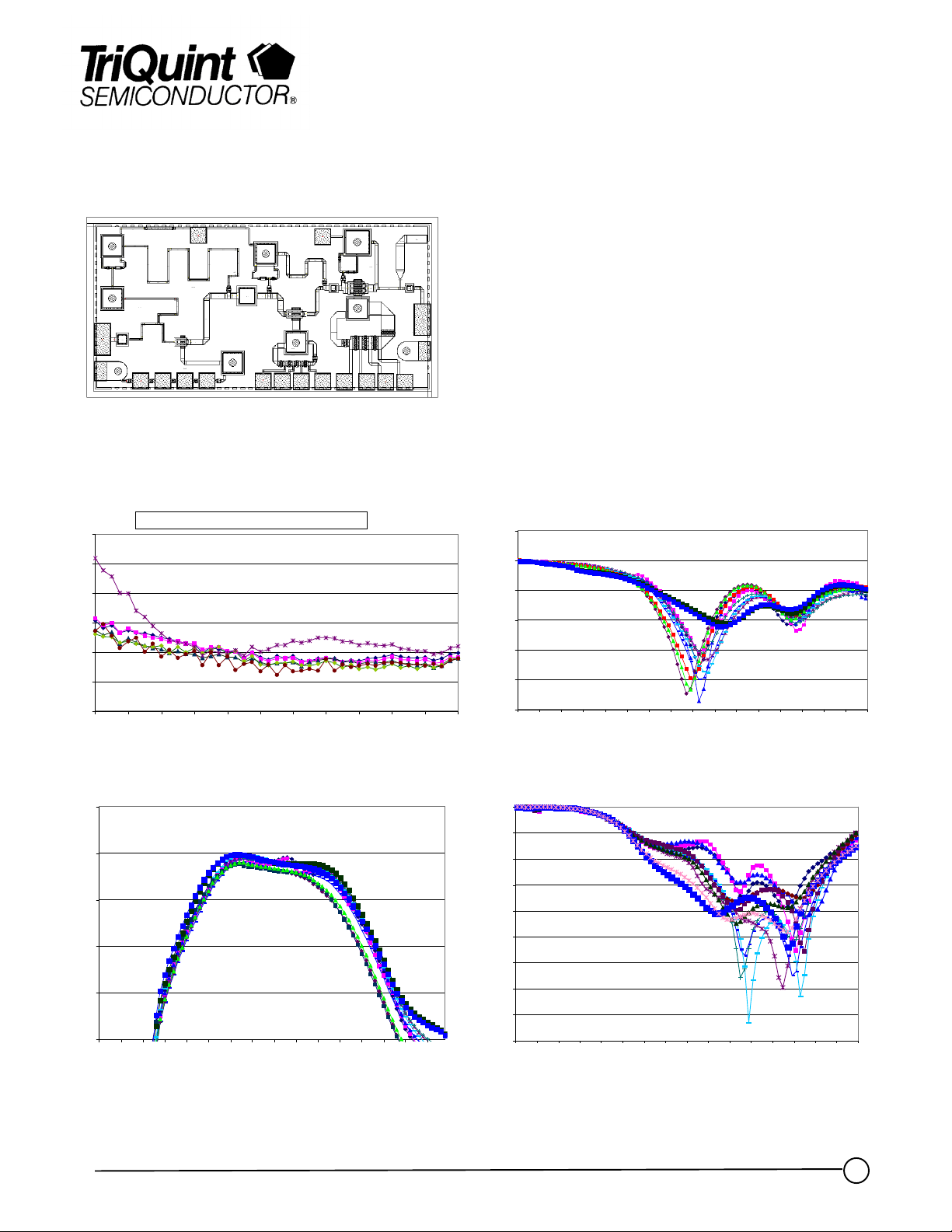
Preliminary Data, 6-10 Fixtured samples @ 25C
6.0
5.0
4.0
3.0
2.0
1.0
0.0
15.0 16.0 17.0 18.0 19.0 20.0 21.0 22.0 23.0 24.0 25.0 26.0
two 1-mil ball bonds at RF interconnects
Frequency (GHz)
NF @ 25C
25
20
15
S21
(dB)
10
5
0
1 3 6 8 11 13 16 18 21 23 26 28 31 33 36 38
Frequency (GHz)
Primary Applications
• Point-to-Point Radio
• Point-to-Multipoint Communications
5
0
-5
S11
-10
(dB)
-15
-20
-25
1 3 6 8 11 13 16 18 21 23 26 28 31 33 36 38
0
-5
-10
-15
-20
dB)
-25
-30
-35
-40
-45
1 3 6 8 111316182123262831333638
Frequency (GHz)
S11 @ 25C
Frequency (GHz)
Gain @ 25C
S22 @ 25C
Note: Devices designated as EPU are typically early in their characterization process prior to finalizing all electrical and process
specifications. Specifications subject to change without notice
TriQuint Semiconductor Texas : Phone (972)994-8465 Fax (972)994 8504 Web: www.triquint.com
1
Page 2
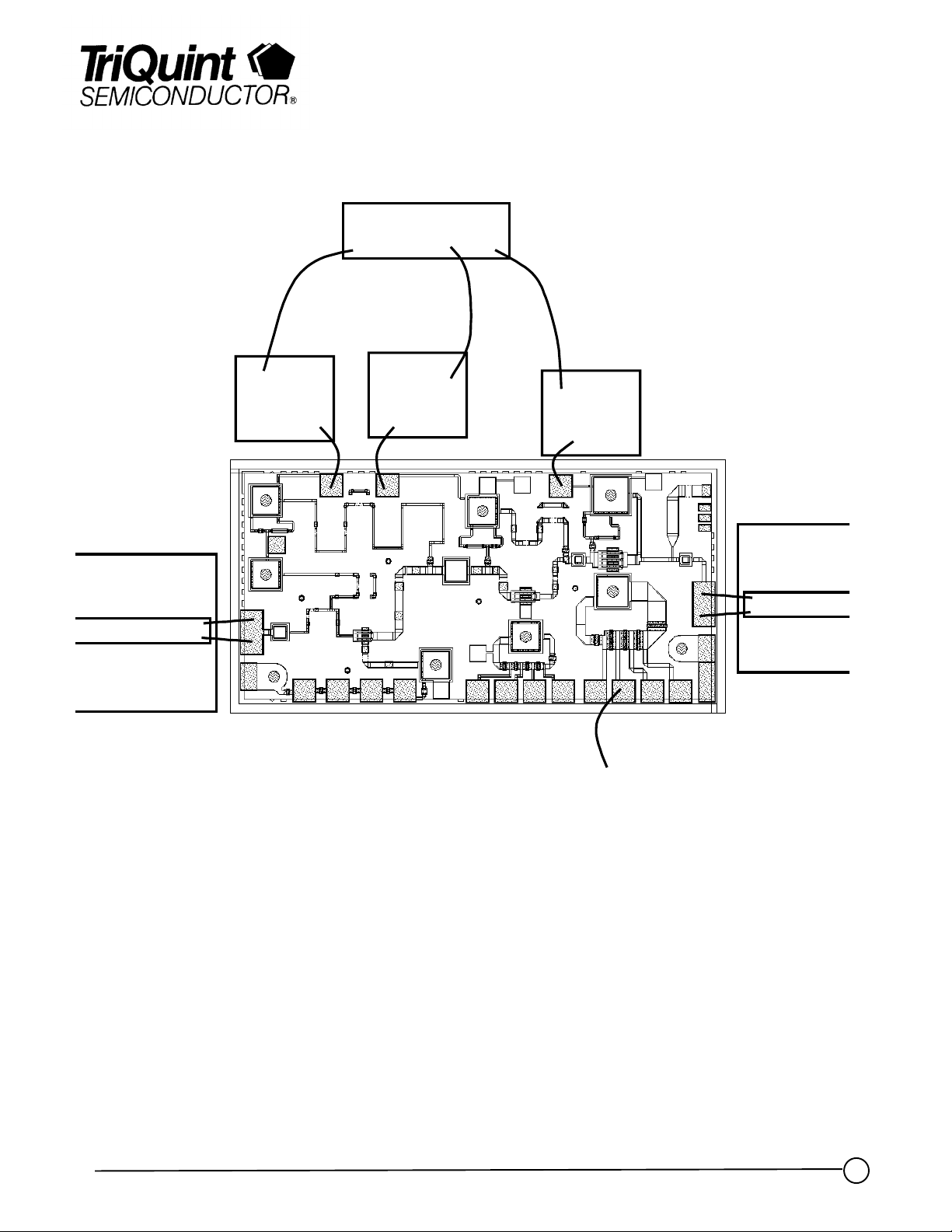
Vd=3V
Advance Product Information
August 29, 2000
TGA1319B
100
pF
100
100
pF
pF
Gnd
TGA1319B - Recommended Assembly Drawing
Note: Devices designated as EPU are typically early in their characterization process prior to finalizing all electrical and process
specifications. Specifications subject to change without notice
TriQuint Semiconductor Texas : Phone (972)994-8465 Fax (972)994 8504 Web: www.triquint.com
Page 3

Advance Product Information
Assembly Process Notes
Reflow process assembly notes:
•=
AuSn (80/20) solder with limited exposure to temperatures at or above 300ΓC
•=
alloy station or conveyor furnace with reducing atmosphere
•=
no fluxes should be utilized
•=
coefficient of thermal expansion matching is critical for long-term reliability
•=
storage in dry nitrogen atmosphere
Component placement and adhesive attachment assembly notes:
•=
vacuum pencils and/or vacuum collets preferred method of pick up
•=
avoidance of air bridges during placement
•=
force impact critical during auto placement
•=
organic attachment can be used in low-power applications
•=
curing should be done in a convection oven; proper exhaust is a safety concern
•=
microwave or radiant curing should not be used because of differential heating
•=
coefficient of thermal expansion matching is critical
August 29, 2000
TGA1319B
Interconnect process assembly notes:
•=
thermosonic ball bonding is the preferred interconnect technique
•=
force, time, and ultrasonics are critical parameters
•=
aluminum wire should not be used
•=
discrete FET devices with small pad sizes should be bonded with 0.0007-inch wire
•=
maximum stage temperature: 200ΓC
GaAs MMIC devices are susceptible to damage from Electrostatic Discharge. Proper precautions should
be observed during handling, assembly and test.
Note: Devices designated as EPU are typically early in their characterization process prior to finalizing all electrical and process
specifications. Specifications are subject to change without notice.
TriQuint Semiconductor Texas : Phone (972)994-8465 Fax (972)994 8504 Web: www.triquint.com
 Loading...