

Page 1
Advance Product Information
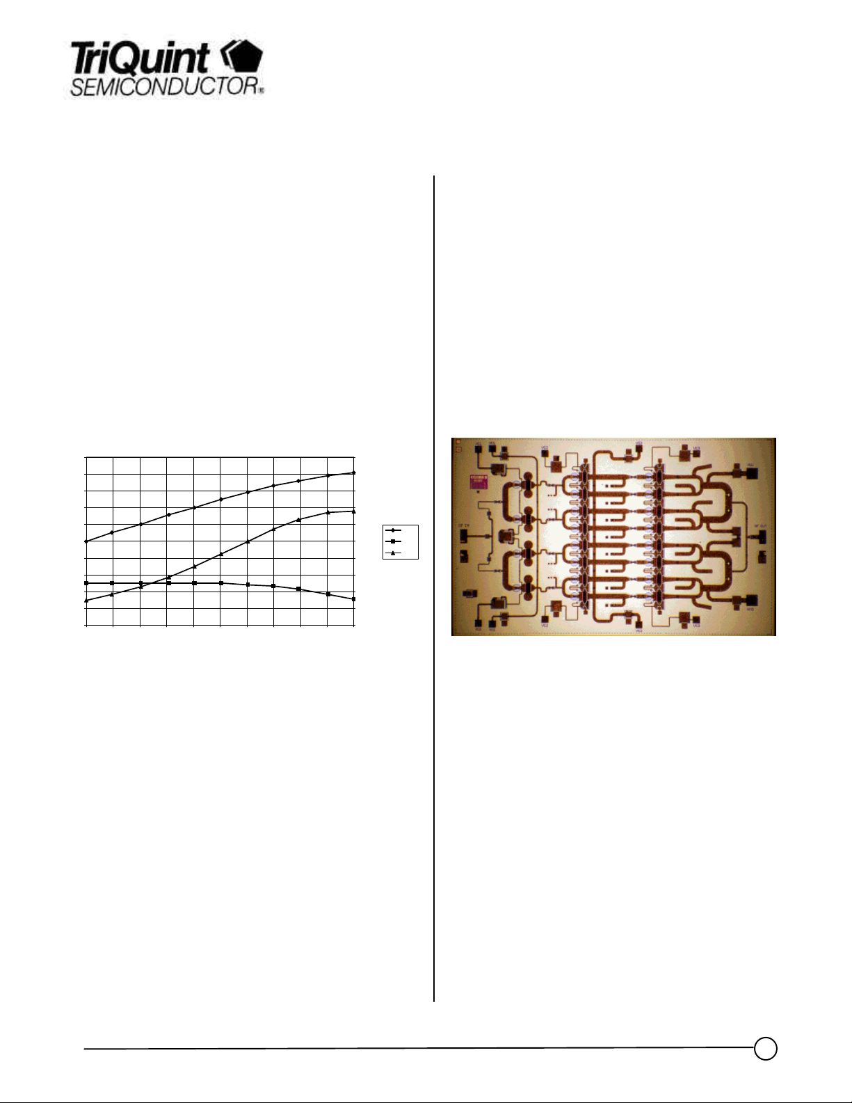
Bias Testing: Vd=7V, Id=1.38A, T=25C, Freq=29GHz
Ka Band 2 Watt Power Amplifier TGA1055-EPU
Key Features and Performance
• 0.25 um pHEMT Technology
• 20 dB Nominal Gain
• 2W Nominal Pout
• -30 dBc IMR3 @ 26 dBm SCL
• Bias 7V @ 1.4 A
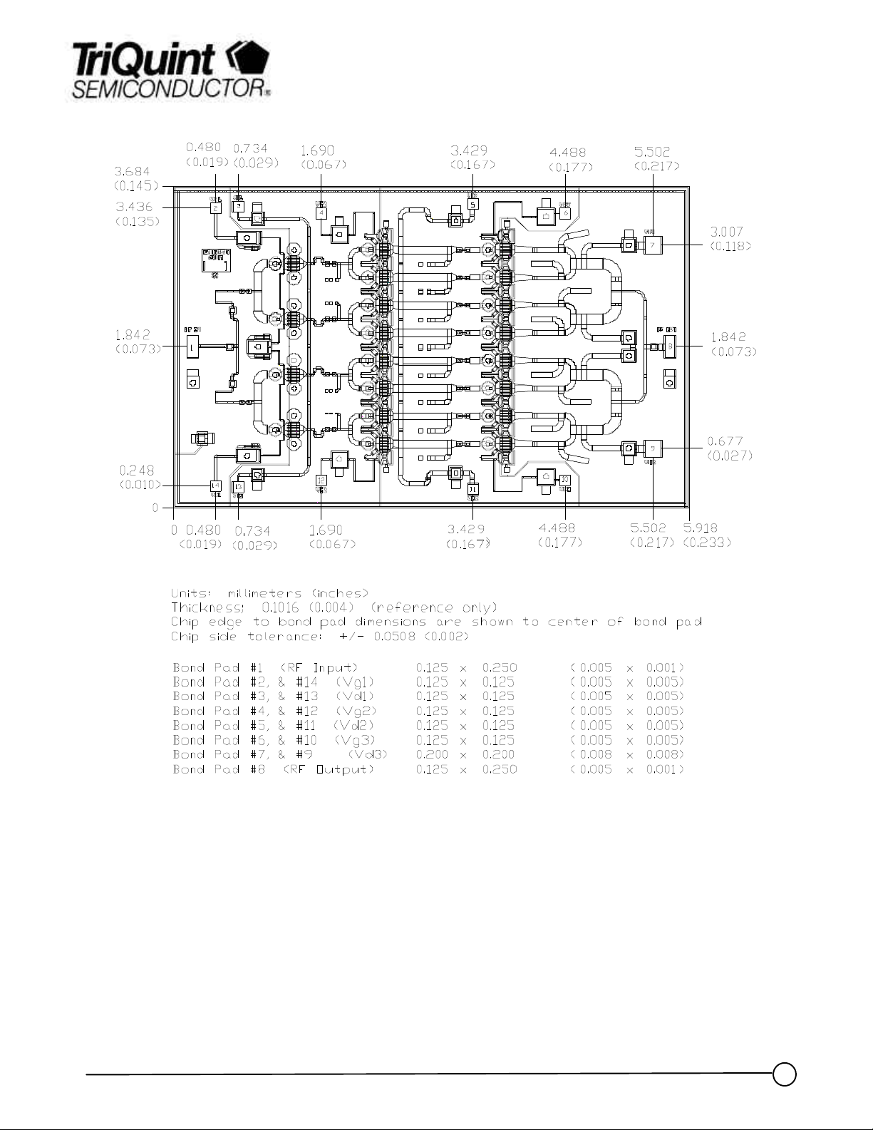
• Chip Dimensions 5.89 mm x 3.66 mm
EG1055B
35
33
31
29
27
25
23
21
19
Output Power (dBm) & Gain (dB)
17
15
5 6 7 8 9 10 11 12 13 14 15
Input Power (dBm)
Preliminary Pout, Gain and PAE Data at 29GHz
20
18
16
14
12
10
8
6
4
2
0
Primary Applications
• LMDS
• Point-to-Point Radio
• Satellite Ground Terminal
Release Status
• Currently shipping Engineering
Prototype Units
Pout
Gain
PAE
Power Added Efficiency (%)
Chip Dimensions 5.89 mm x 3.66 mm
Note: Devices designated as EPU are typically early in their characterization process prior to finalizing all electrical and process
specifications. Specifications are subject to change without notice.
TriQuint Semiconductor Texas : Phone (972)994 8465 Fax (972)994 8504 Web: www.triquint.com
1
1
Page 2
Advance Product Information
TriQuint Semiconductor Texas : Phone (972)994 8465 Fax (972)994 8504 Web: www.triquint.com
2
Page 3

Advance Product Information
Chip Assembly and Bonding Diagram
Reflow process assembly notes:
•
AuSn (80/20) solder with limited exposure to temperatures at or above 300♣C
•
alloy station or conveyor furnace with reducing atmosphere
•
no fluxes should be utilized
•
coefficient of thermal expansion matching is critical for long-term reliability
•
storage in dry nitrogen atmosphere
Component placement and adhesive attachment assembly notes:
•
vacuum pencils and/or vacuum collets preferred method of pick up
•
avoidance of air bridges during placement
•
force impact critical during auto placement
•
organic attachment can be used in low-power applications
•
curing should be done in a convection oven; proper exhaust is a safety concern
•
microwave or radiant curing should not be used because of differential heating
•
coefficient of thermal expansion matching is critical
Interconnect process assembly notes:
•
thermosonic ball bonding is the preferred interconnect technique
•
force, time, and ultrasonics are critical parameters
•
aluminum wire should not be used
•
discrete FET devices with small pad sizes should be bonded with 0.0007-inch wire
•
maximum stage temperature: 200♣C
GaAs MMIC devices are susceptible to damage from Electrostatic Discharge. Proper precautions should
be observed during handling, assembly and test.
TriQuint Semiconductor Texas : Phone (972)994 8465 Fax (972)994 8504 Web: www.triquint.com
3
 Loading...