

Page 1
TEA2029C
COLOR TV SCANNING AND POWER SUPPLY PROCESSOR
DEFLECTION
.
CERAMIC 500kHz RESONATOR FREQUENCYREFERENCE
.
NO LINE AND FRAME OSCILLATOR ADJUSTMENT
.
DUALPLLFOR LINE DEFLECTION
.
HIGHPERFORMANCE SYNCHRONIZATION
.
SUPERSANDCASTLE OUTPUT
.
VIDEOIDENTIFICATION CIRCUIT
.
AUTOMATIC 50/60Hz STANDARD IDENTIFICATION
.
EXCELLENTINTERLACINGCONTROL
.
SPECIALPATENTED FRAME SYNCHRO DEVICE FOR VCROPERATION
.
FRAMESAW-TOOTH GENERATOR
.
FRAME PHASE MODULATOR FOR THYRISTOR
SMPSCONTROL
.
ERROR AMPLIFIER AND PHASE MODULATOR
.
SYNCHRONIZATION WITH HORIZONTAL
DEFLECTION
.
SECURITY CIRCUIT AND START UP PROCESSOR
.
OUTPUT PULSES ARE SENT TO THE PRIMARY SMPS IC (TEA2261) THROUGH A
LOW COST TRANSFORMER
DESCRIPTION
The TEA2029Cis a complete (horizontal and vertical) deflection processor with secondary to primarySMPS control for color TV sets.
DIP28
(Plastic Package)
ORDER CODE : TEA2029C
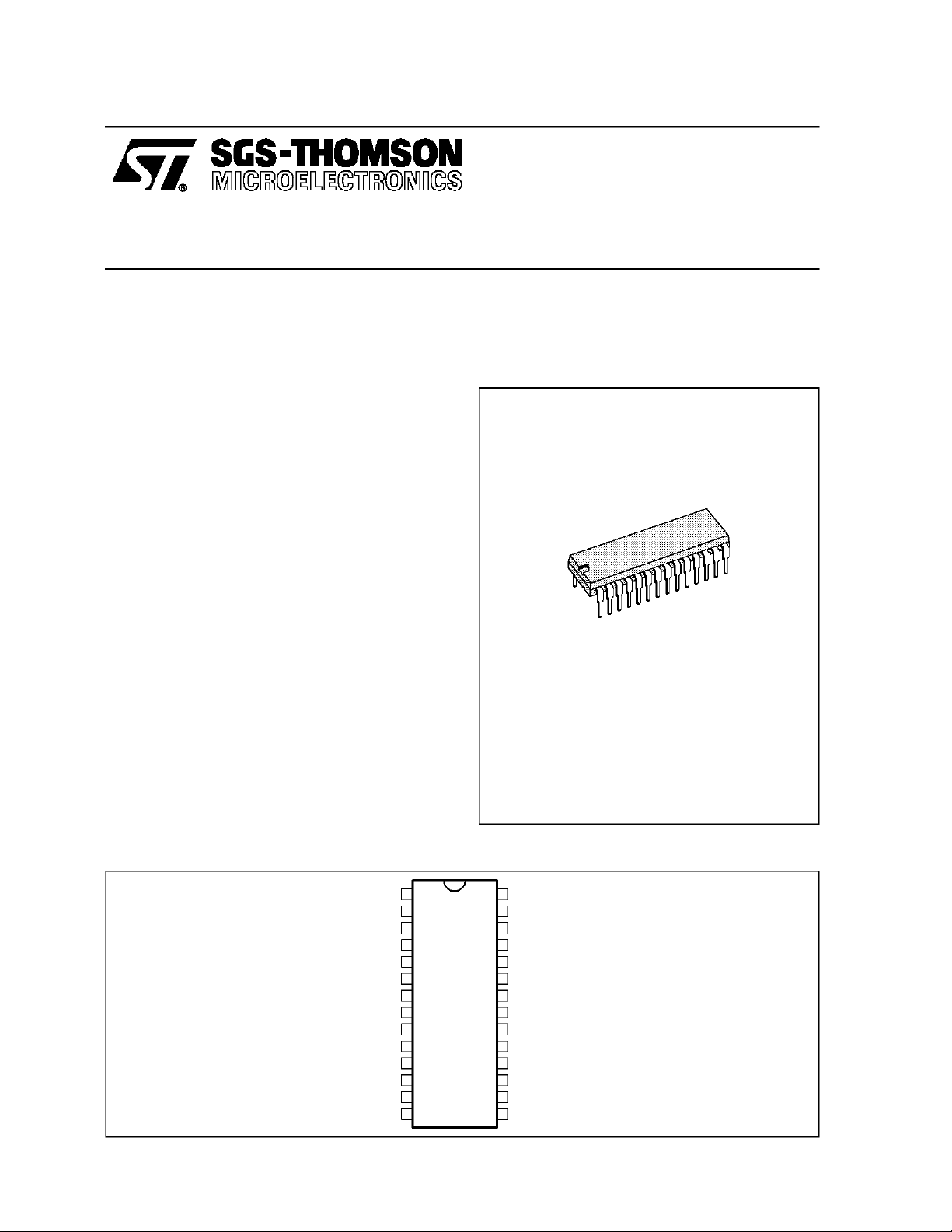
PINCONNECTIONS
August 1993
+ INPUTFRAME AMPLIFIER
- INPUTFRAME AMPLIFIER
FRAMEOUTPUT
FRAME RAMP GENERATOR
GROUND POWER
SWITCH MODE POWER SUPPLYOUTPUT
V
S.M.P.S. INPUT REGULATION
HORIZONTAL OUTPUT
SUPER SANDCASTLE OUTPUT
HORIZONTALFLY-BACKINPUT
HORIZONTALSAW-TOOTH
CURRENT REFERENCE
1
2
3
4
5
6
7
8
CC
9
10
11
12
13
14
SAFETY INPUT
28
VIDEO INPUT
27
HORIZONTAL SYNCHRO CAPACITOR (tiplevel)
26FRAME SAW-TOOTHOUTPUT
VIDEO IDENTIFICATION CAPACITOR
25
MUTING +50/60Hz IDENTIFICATION OUTPUT
24
V.C.R. INPUT
23
PHASE COMPARATOR ϕ1 CAPACITOR
22
GROUND SUBSTRAT
21
A.G.C. KEY PULSEOUTPUT
20
V.C.O. INTPUT
19
V.C.O. OUTPUT
18
V.C.O. 90° REFERENCE
17
PHASE COMPARATOR ϕ2 CAPACITOR
16
STARTING AND SAFETYCAPACITOR
15
2029C-01.EPS
1/9
Page 2
TEA2029C
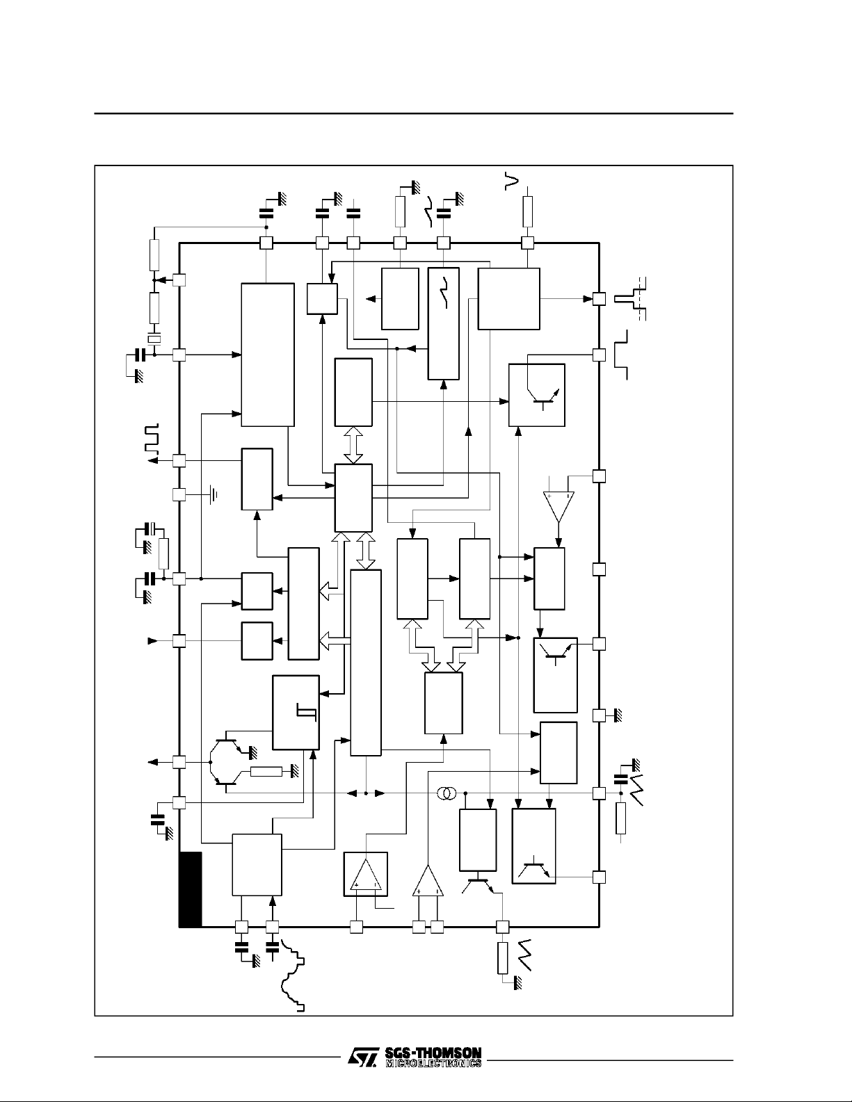
BLOCK DIAGRAM
CC
V
Ω
3.3k
17
16
15
14
13
FLYBACK
HORIZONTAL
12
INPUT
503kHz
AGC
OUTPUT
SUBSTRAT
INPUT
VCR SWITCHING
50/60Hz
MUTING OUTPUT
18
19
2021
GROUND
23 22
2425
SUBST
AGC
KEY PULSE
ϕ1 DET
VCR
INPUT
VCO 500kHZ
ϕ2
ϕ1 INHIBITION TIME
CONSTANT SWITCHING
VIDEO
IDENTIFICATION
1.26VV
R
26µs
CONSTANT
PULSE WIDTH
HORIZONTAL
LOGIC TIMING
FRAME TIMING
µs
2
IDENTIFICATIONLOGIC
50/60Hz
VOLTAGE
CURRENT
REFERENCE
SWITCH ON/OFF
SAFETY CIRCUIT
GENERATOR
H. SAWTOOTH
SOFT STARTING
LOGIC
SAFETY
50/60
CIRCUIT
Hz
SUPER
SANDCASTLE
H. OUTPUT
H. INHIBIT
INHIB.
1.26VV
R
S.M.P.S.
ϕ MODULAT.
S.M.P.S.
OUTPUT
PHASE
FRAME
MODULAT.
S SCOUTPUT
11
109
8
7
6
5
CC
V
POWER
OUTPUT
HORIZONTAL
GROUND
FRAME
SAWTOOTH
2/9
H. SYNC
HORIZONTAL
TEA2029C
26
SYNCHRO
SYNCHRO
AND FRAME
27
SAFETY
VIDEO INPUT
INPUT
FRAME
FRAME
OUTPUT
AMPLIFIER
FRAME ERROR
1.26VV
R
28
1
SAWTOOTH
2
OUTPUT
4
3
FRAME
OUTPUT
SAWTOOTH
2029C-02.EPS
Page 3

TEA2029C
GENERALDESCRIPTION
2
This integrated circuit uses I
L bipolar technology
and combinesanalogsignalprocessingwithdigital
processing.
Timing signalsareobtainedfromavoltage-controlledoscillator(VCO) operatingat500KHzbymeans
of a cheap ceramic resonator. This avoids the
frequency adjustment normally required with line
and frame oscillators.
A chain of dividers and appropriate logic circuitry
produce very accurately defined sampling pulses
and the necessarytimingsignals.
The principalfunctionsimplementedare :
- Horizontalscanning processor.
- Framescanning processor.Two applicationsare
possible:
- D Class : Power stage using an external
thyristor.
- B Class : Powerstageusingan externalpower
amplifier with fly-back generator
suchas the TDA8170.
- Secondaryswitch mode power regulation.
The SMPS output synchronize a primary I.C.
(TEA2260/61)at the mains part.
ThisconceptallowsACTIVESTANDBYfacilities.
- Dualphase-lockedloop horizontalscanning.
- Highperformanceframeandlinesynchronization
with interlacing control.
- Videoidentificationcircuit.
- Supersandcastle.
- AGCkey pulse output.
- Automatic50-60Hz standardidentification.
- VCRinput for PLL time constant and frame synchro switching.
- Frame saw-tooth generator and phase modulator.
- Switchingmoderegulatedpowersupplycomprising erroramplifier and phasemodulator.
- Securitycircuit and start-up processor.
- 500kHzVCO
The circuit is supplied in a 28 pinDIP case.
= 12V.
V
CC
SynchronizationSeparator
Line synchronization separator is clamped to
black level of input video signal with synchronizationpulse bottom level measurement.
The synchronization pulses are divided centrally
between the black level and the synchronization
pulse bottom level, to improve performance on
videosignals in noiseconditions.
FrameSynchronization
Framesynchronizationis fully integrated (no ex-
ternalcapacitorrequired).
The frame timing identificationlogic permits automatic adaptationto 50 - 60Hz standards or non-in-
terlacedvideo.
An automatic synchronization window width sys-
tem provides:
- fast frame capture (6.7ms wide window),
- good noise immunity (0.4ms narrow window).
The internal generator starts the dischargeof the
saw-tooth generator capacitor so that it is not disturbed by line fly back effects.
Thanks to the logic control, the beginning of the
charge phase does not dependon any disturbing
effectof the line fly-back.
A32µs timing is automatically applied on stan-
dardizedtransmissions, for perfect interlacing.
In VCR mode, the discharge time is controlled by
an internal monostable independent of the line
frequency and gives a direct frame synchronization.
HorizontalScanning
Thehorizontalscanningfrequencyisobtainedfrom
the 500kHz VCO.
The circuitusestwo phase-locked loops (PLL) :
the firstonecontrolsthefrequency,thesecondone
controls the relative phase of the synchronization
and linefly-back signals.
The frequency PLL has two switched time constants to provide :
- capture with a short time constant,
- good noise immunity after capture with a long
time constant.
The output pulse has a constant duration of 26µs,
independentof V
and any delay in switching off
CC
the scanningtransistor.
Video Identification
The horizontal synchronization signal is sampled
by a 2µs pulse within the synchronization pulse.
The signalis integrated by an externalcapacitor.
The identificationfunction provides three different
levels :
- 0V : no video identification
- 6V : 60Hz video identification
- 12V: 50Hz video identification
This information may be used for timing research
in thecaseoffrequencyor voltagesynthetizertype
receivers,and for audio muting.
SuperSandcastle with 3 levels : burst, line flyback, frame blanking
In theevent of vertical scanning failure, the frame
blankinglevel goes high to protect the tube.
Frame blanking time (start with reset of Frame
divider) is 24 lines.
VCR Input
This provides for continuous use of the shorttime
constantofthefirst phase-lockedloop(frequency).
In VCR mode, the frame synchronization window
3/9
Page 4
TEA2029C
widens out to a search window and there is no
delay of frame fly-back (direct synchronization).
FrameScanning
FRAMESAW-TOOTHGENERATOR. The current
to chargethecapacitorisautomaticallyswitched to
60Hzoperation to maintain constant amplitude.
FRAMEPHASE MODULATOR (WITH TWO DIFFERENTIAL INPUTS). The outputsignalis a pulse
at the line frequency,pulsewidth modulatedby the
voltageat the differential pre-amplifierinput.
This signal is used to control a thyristor which
provides the scanning current to the yoke. The
saw-toothoutputisa lowimpedance,however,and
can therefore be used in class B operation with a
poweramplifier circuit.
Switch Mode Power Supply (SMPS)Secondary to PrimaryRegulation
Thispowersupplyusesa differentialerror amplifier
with an internal reference voltage of 1.26V and a
phase modulator operating at the line frequency.
Thepowertransistoristurnedoffbythe fallingedge
of thehorizontalsaw-tooth.
The ”soft start” device imposes a very small con-
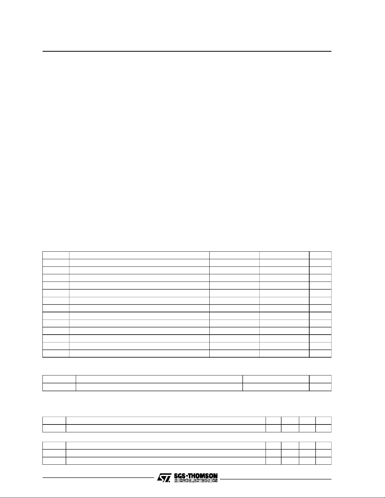
ABSOLUTEMAXIMUMRATINGS (limitingvalues) T
Symbol Parameter Min. Max. Unit
Supply Voltage (pin 8) 14 V
VCC Operating Supply Voltage (pin 8) Starting threshold 13.2 V
I
I
V
I
I
I
V
V1/V2Common Mode Range (pins 1-2) 10 V
AGC Current (pin 20) 5 mA
20
Video Identification Current (pin 24) 10 mA
24
Negative Line Retrace Voltage(pin 12) – 20 V
12
Line Retrace Current (pin 12) + 10 mA
12
Line Output Current (pin 10) – 10 40 mA
10
I
Frame Saw-tooth Generator (pin3) 20 mA
3
I
Frame Output Current (pin 4) 100 mA
4
I
SMPS Output Current (pin 7) – 40 40 mA
7
Safety Input Current (pin 28) 5 mA
28
Safety Input Voltage (pin 28) V
28
duction angle on starting up, this angle progressivelyincreasesto its nominal regulation value.
The maximumconductionangle may bemonitored
by forcing a voltage on pin 15. This pin may also
be used for currentlimitation.
TheoutputpulseissenttotheprimaryS.M.P.S.I.C.
(TEA2261)via a lowcost synchro transformer.
SecurityCircuit and Start Up Processor
When the security input (pin 28) is at a voltage
exceeding 1.26V the three outputsare simultaneouslycutoffuntilthisvoltagedropsbelowthe 1.26V
threshold again. In this case the switch mode
powersupplyis restartedbythe ”soft start”system.
If this cycle is repeated three times, the three
outputs are cut off definitively.To reset thesafety
logic circuits,V
mustbe zero volt.
CC
This circuit eliminates the risk toswitch off the TV
receiver in the event of a flashaffectingthe tube.
On startingup, thehorizontaland verticalscanning
functions come into operation at V
= 6V. The
CC
power supply then comes into operation progressively.
On shutting down, the three functions are interrupted simultaneouslyafter the first linefly-back.
=25°C (unless otherwisenoted)
amb
CC
2029C-01.TBL
THERMALDATA
Symbol Parameter Value Unit
R
th (j-a)
Junction-ambient Thermal Resistance 55 °C/W
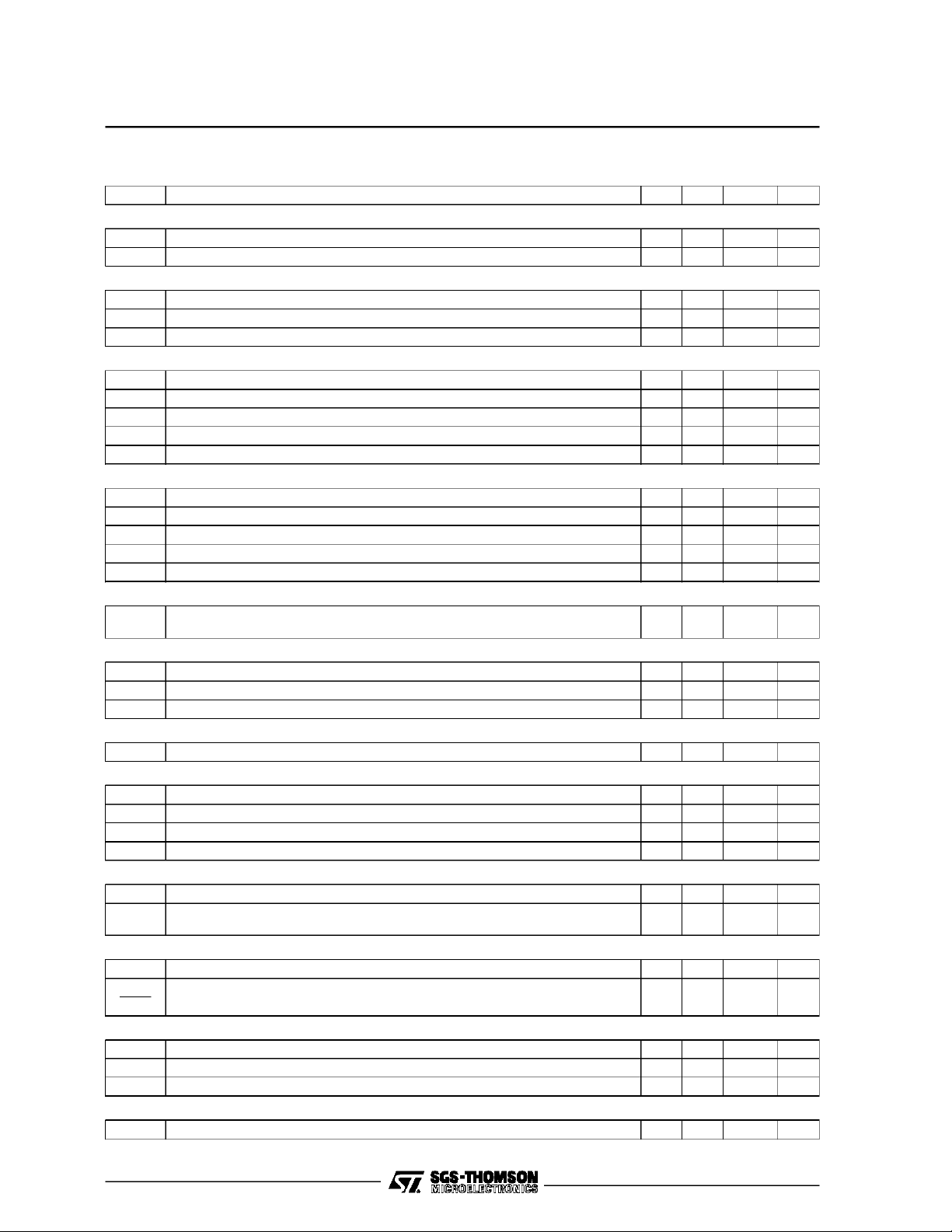
ELECTRICAL OPERATING CHARACTERISTICS
=25°CVCC= 12V (unless otherwise noted) Pulse duration at 50%of theampl.
T
amb
Symbol Parameter Min. Typ. Max. Unit
I
Supply Current (pin 8, frame, line and SMPS output without load) 50 80 mA
CC
SYNCH SEPARATOR (Pins 26-27)
Positive Video Input AC Coupled (output impedance of signal source < 200Ω) 0.2 1.8 3 V
–I
4/9
Negative Clamping Current (during synch, pulse) - 25 - 40 - 55 µA
27
I
Clamping Current - Pin for slicing level 0.2V < V
27
< 2V (50% ofsync amplitude) 3 6 9 µA
27pp
2029C-02.TBL
pp
2029C-03.TBL
Page 5
TEA2029C
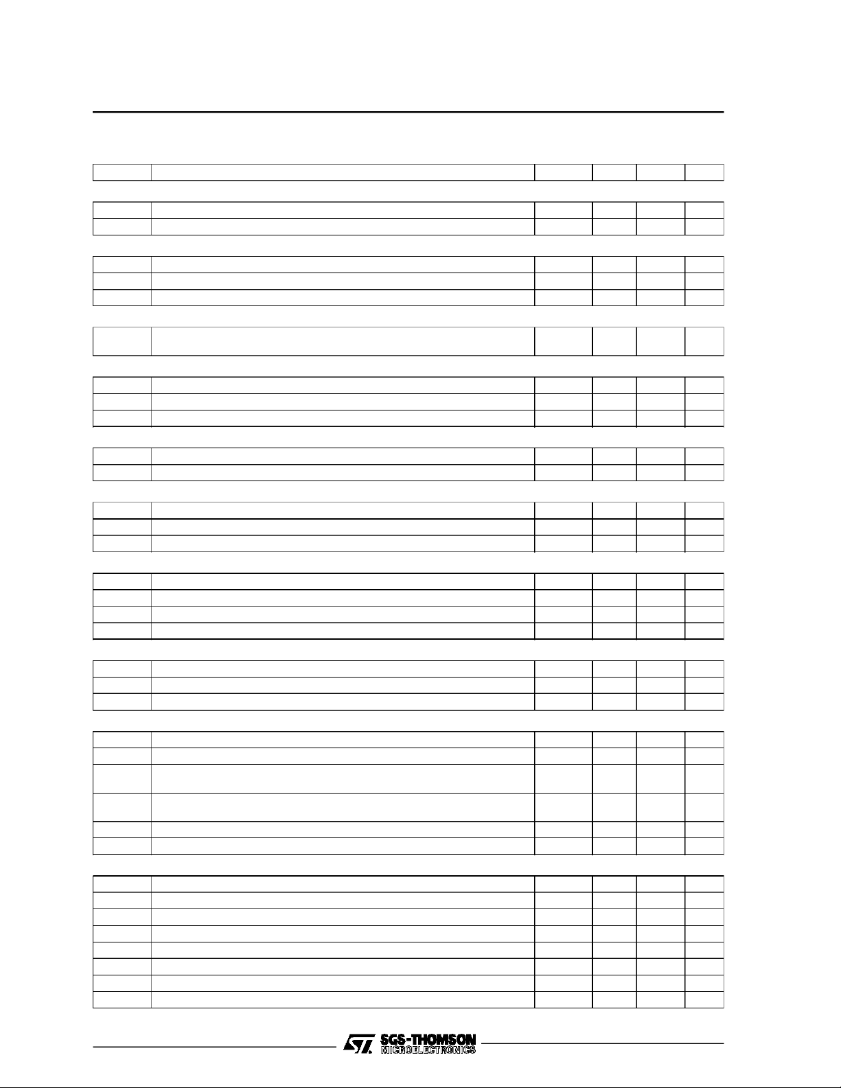
ELECTRICAL OPERATING CHARACTERISTICS (continued)
Symbol Parameter Min. Typ. Max. Unit
SYNCH SEPARATOR (Pins 26-27) (continued)
–I
PULSE FOR KEYED AGC (Pin 20) - Positive (function : without video signal: low level, withvideo signal: key pulses)
V
VCO (Pins 17-18 and 19)
PHASE COMPARATOR ϕ 1 (Pin 22)
VCR SWITCHING(Pin 23)
VIDEO IDENTIFICATION (Pin 24)
V
VIDEO IDENTIFICATION (Pin 25)
V
L
H-RAMP GENERATOR (Pin 13)
I
ch13
V
I
dis13
SUPER SANDCASTLE (Pin 11)
V
V
V
T
T
NEGATIVELINE FLY-BACK INPUT (Pin 12)
V
V
Positive Current 0 - 0.75 - 1 nA
26
I
Negative Current 17 25 36 µA
26
Output Current 5mA
I
20
Output Saturation Voltage (I20= 5 mA) 0.25 0.4 V
20
t
Pulse width (synchro pulse is always inside the key pulse) 6.5 8 8.5 µs
k
Frequency control range after line divider
(ceramic resonator : 503 kHz)
15.30 to
16.10
Output Current Low Loop Gain ± 0.35 ± 0.50 ± 0.65 mA
Output Current High Loop Gain ± 1 ± 1.5 ± 2mA
Window Pulse Width 7 10 13 µs
Threshold Voltage VCR Operating 1.7 2.2 2.7 V
Input Current (V23=0VCC= 12V) - 0.030 - 0.25 - 1 mA
I
23
Output Saturation Voltage (without video signal, I24= 3 mA) 0.2 0.6 V
24
Output Voltage (with 60 Hz video signal, I
Output Voltage (with 50 Hz video signal, I
Output Current (charging the capacitor) 0.5 0.75 1 mA
I
25
t
Identification Time (charging the capacitor) 1.3 1.7 2.2 µs
25
Threshold (voltage changing from lower to higher value) 4 4.5 5 V
25
Hysteresis 150 240 400 mV
HYS
= 2.5 mA) 5 6.5 0.6 V
24
=10µA) 11 11.5 7.5 V
24
Charge Current 185 200 215 µA
Base Voltage of Saw-tooth 0.5 V
I13
Discharge Current 3.5 7 mA
Burst Key Pulse Level Output Voltage (I11= - 5mA) 9 V
B11
Line Blanking Pulse Level Output Voltage(I11= - 5mA) 4 4.5 5 V
L11
Frame Blanking Pulse Level OutputVoltage
BT11
(and frame out of function) (I
Delay between Middle of Synch Pulse (pin 27) and Leading
B11
Edge of Burst Key Pulse
= - 5mA)
11
2 2.5 3 V
2.3 3 µs
Duration of Burst Key Pulse 3.7 4 5 µs
Delay between SSC Cutting at Pin 12 and Line Blanking Pulse 0.35 µs
O11
Threshold for SMPS Safety 1.1 V
Threshold for Blanking 11 11.5 12 V
bl12
Threshold for PLL2 - 1 V
ϕ12
I
Input Current 11V < V
12
I
Input Current 1.3V < V12< 11V -3 3 µA
12
I
Input Current 0V < V12< 1.3V 0 -80 µA
12
I
Input Current - 1V < V12<0V 0 -1 -2 mA
12
12
- 200 µA
Line Blanking Trigger 80 µA
kHz
2029C-04.TBL
5/9
Page 6
TEA2029C
ELECTRICAL OPERATING CHARACTERISTICS (continued)
Symbol Parameter Min. Typ. Max. Unit
PHASE COMPARATOR ϕ2 (Pin 16)
Charging Current 0.4 0.6 0.8 mA
I
16
Delay betweenthe Edges of ϕ1 and ϕ2(f
LINE OUTPUT (OPEN COLLECTOR) (Pin10)
Output Voltage (I
T
Output PulseDuration(when fly-back pulse is with in time T10)(f
10
= 20mA) 1 1.5 V
10max
∆t ϕ2 Phase Range 15 16 19 µs
FRAME LOGIC
Free Running Period (with mute signal) 315 Line
Search Window 247 361 Line
50Hz Window 309 315 Line
60Hz Window 247 276 Line
VCR Mode Window 247 361 Line
FRAME SAW-TOOTH GENERATOR (Pins 3-5)
Saw-tooth Amplitude 2 3 4 V
I5(60) SInternal Current Generator (60Hz on) 12 14 16 µA
Discharging Time (with C = 0.47µF, ∆V < 4V) 50 70 µs
V
Starting Level (0mA < IS< 0mA) 1 1.26 1.4 V
S
Saw-tooth Amplitude (I
= 10mA) 2 3 4 V
S
FRAME FEEDBACK INPUTS (Pins 1-2)
Positive and Negative Input Current (V1-V2) > 25mA for frame blanking
I
1,2
safety
FRAME OUPUT (Pin4)
Output Voltage (0mA < |I
T
ON
max (f
= 500kHz) 36 40 41 µs
VCO
| < 80mA) 10 V
4
Output PhaseRange 0 t
SMPS CONTROL INPUT (Pin 9)
Input Current (V9=V
I
9
)2µA
ref 14
SMPS OUTPUT (Pin 7) - No Relationbetween End of SMPS Pulse (pin 7) and Leading Edge of Line Flyback (pin 12)
Output Voltage (0 < I7< 20mA) 10 V
V
7
T
t
7
ON max(fVCO
Nominal Time (V
= 500kHz) 30 32 34 µs
9=Vref 14
)2631µs
Output PhaseRange 0 t
SAFETY INPUT (Pin 28)
Threshold Voltage (V28=V
V
28
Input Current (if V
during the next line retrace)
28>Vref 14
) 1.15 1.26 1.37 V
ref 14
then SMPS, line and frame are switched off
SWITCH-ON, SWITCH-OFF PROCESSING (Pin15)
I
I
I
dis 15
Charging Current (tC=4µs, T = 64µs) 70 130 µA
ch 15
ch 15
Ratio Charging/discharging 0.8 1 1.2 µA
STARTING SUPPLY VOLTAGE (Pin 8)
V
V
V
SMPS*, Frame andLineStarting (pins7, 10 and 4) 5.25 6.5 V
CC
SMPS Stopping during Line Retrace 5.25 6.5 V
CC
Frame and Line Stopping 5.25 6.5 V
CC
CURRENT REFERENCE (PIn 14)
V
Voltage Reference 1.2 1.26 1.35 V
ref 14
= 500kHz) 1.5 2 2.8 µs
VCO
= 500kHz) 24 26 30 µs
VCO
10 µA
ON max
ON max
3 µA
PP
PP
µs
2029C-05.TBL
6/9
Page 7
TEA2029C
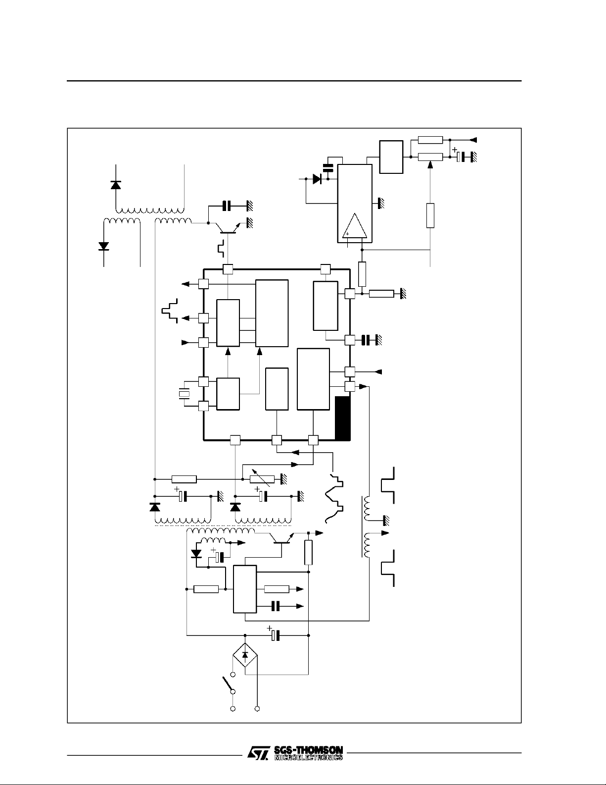
APPLICATIONWITH TDA8172 FOR B CLASS FRAME POWER AND TEA2261 FOR SECONDARY
SMPSREGULATION
CC2
V
EHT
OUTPUT
VIDEO IDENTIFICATION
S.S.C
VCR
500kHz
18 19 23 11 24
10
HORIZONTAL
VCO
8
CC
V
2
IL
+
LOGIC
DIVIDER
SYNC.
SEPARAT.
27
CC2
V
4
FRAME
MODULAT.
SUPPLY
SWITCHING
REGUL.POWER
9
TDA8172
VERTICAL
AMPLIFIER
BIAS
3
5287
TEA2029C
YOKE
FRAME
INPUT
SAFETY
+140V
+12V
V+
TEA2261
IN OUT
220V
MAINS
VIDEO
2029C-03.EPS
7/9
Page 8
TEA2029C
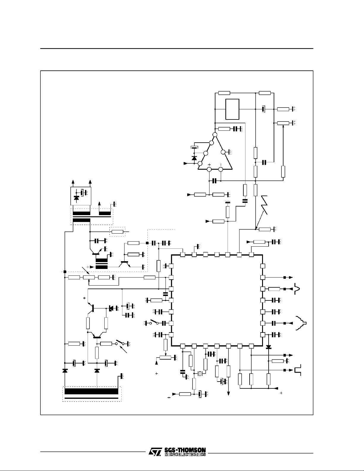
COMPLETE APPLICATION WITH B CLASS FRAME POWER
Ω
220
VERTICAL
PHASE
SHIFT
Ω,
+200V
EHT
TRANSFORMER
SMPS
OUTPUT VOLTAGE
Ω
150k
+24V
ADJUST
1kΩ
CC
V
2N1711
27Ω
LINE
BC307
FLYBACK
1kΩ
12V
680Ω
Line
0.7App
Frame Yoke
32mH, 15
1000µF
Ω
2
33kΩ
CC
V
6
NC
4
5
3
TDA8172
7
1nF
2.2
100nF
4
1
13kΩ
10kΩ
3.3kΩ
NC
1
2
TEA2029C
Ω680kΩ150kΩ
470k
100nF
Ω
15nF 10k
FRAME
SAWTOOTH
2.2kΩ
2.7M Ω
200V
5
3
1112
252627 28
15
µF
100
1N4001
+24V
Pin 14
(TEA2029)
1nF
390Ω
VCR
SWITCH
47nF
Ω
1k
1.5kΩ
22nF
3.32kΩ -1%
3.3nF
22nF
10
21
89
13 14
23
16
6
Yoke
1kΩ
µF
220
100nF
15kΩ
470nF
47kΩ
4.7nF
100nF
220nF
100nF
Ω 1Ω
100
ADJUST
VERTICAL AMPLITUDE
SUPER
LINE
FLYBACK
VIDEO
OUTPUT
SANDCASTLE
INPUT
8/9
BY218
SMPS
POWER
TRANSFORMER
17
18
470
19
1.5nF
220Ω
503kHz
220Ω
10µF
Ω
3.3kΩ
µF 10k
BY218
1000µF 22kΩ
1000
STANDBY
MODE SWITCH
470kΩ
CC
V
Adjust
Phase
Horizontal
CC
V
Ω
22k
1.8kΩ
150pF
Ω
7
TO SMPS
CONTROL
20
24
330Ω
Ω
5.6kΩ
5.6k
1N4148
15kΩ
&
50/60Hz
MUTE OUT
8.2kΩ
CC
V
AGC
PULSE
IDENTIFICATION
2029C-04.EPS
22
3.9kΩ
4.7µF 15nF
Page 9
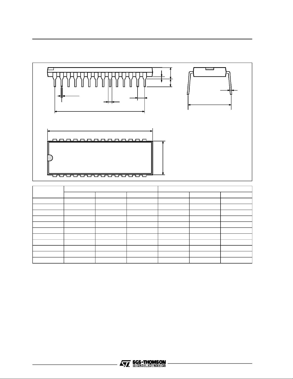
PACKAGEMECHANICAL DATA
28 PINS- PLASTICDIP
TEA2029C
I
L
E
F
28
114
Dimensions
a1
b
b2
e3
D
e
15
Millimeters Inches
Min. Typ. Max. Min. Typ. Max.
a1 0.63 0.025
b 0.45 0.018
b1 0.23 0.31 0.009 0.012
b2 1.27 0.050
D 37.4 1.470
E 15.2 16.68 0.598 0.657
e 2.54 0.100
e3 33.02 1.300
F 14.1 0.555
i 4.445 0.175
L 3.3 0.130
b1
PM-DIP28.EPS
DIP28.TBL
Information furnished isbelieved to be accurate and reliable. However, SGS-THOMSON Microelectronics assumes no responsibility
for the consequences ofuse of such information nor forany infringement of patentsor other rights of third parties which may result
from itsuse. No licence isgranted by implicationor otherwiseunder any patent orpatent rights ofSGS-THOMSON Microelectronics.
Specifications mentioned in this publication are subject to change without notice. This publication supersedes and replaces all
information previously supplied.SGS-THOMSON Microelectronics products arenot authorized for useas critical components in life
support devices or systems without express written approval of SGS-THOMSON Microelectronics.
1994 SGS-THOMSON Microelectronics - All Rights Reserved
Purchase of I
2
I
C Patent.Rights to use these components in a I2C system, is granted provided that thesystem conforms to
Australia - Brazil - China - France - Germany - Hong Kong - Italy - Japan - Korea - Malaysia - Malta - Morocco
The Netherlands- Singapore - Spain - Sweden - Switzerland - Taiwan - Thailand - United Kingdom - U.S.A.
2
C Components of SGS-THOMSON Microelectronics, conveys a license under the Philips
2
the I
C Standard Specifications as defined by Philips.
SGS-THOMSON Microelectronics GROUP OF COMPANIES
9/9
 Loading...